Abstract—This paper introduces a new algorithm for the early
detection of abnormal arcing conditions of circuit breakers (CBs). Any interruption with a higher arcing time compared to maximum permissible arcing time (MPAT) of CB is defined as a CB failure to clear mode. Measuring CB arcing time is not easy because there is no control on the mechanical opening and closing instants of CB contacts. Nevertheless, there is a correlation between the spectral energy densities of CB arcing voltages and arcing times of CB. This correlation is used by calculating the spectral energy densities of the instantaneous system voltage and the instantaneous CB voltage across its terminals utilizing discrete Fourier transform (DFT) for two periods of the system frequency. The difference between the spectral energy densities at the fundamental frequency is defined as a criterion for identifying a failure to clear mode. Whenever this criterion exceeds a predefined trip level, it indicates the occurrence of a failure to clear mode. In this situation, a trip signal is initiated for adjacent CBs to isolate the faulted CB and the fault. The results obtained from computer simulations and measurements show that the algorithm discriminates between normal and abnormal arcing conditions of CB.
Index Terms—Circuit breakers, discrete Fourier transform,
failure detection, fundamental frequency, voltage measurement.
I. INTRODUCTION
HE issue of protecting power circuit breakers (CBs) against failures has been a main source of concern for transmission and distribution system operators in order to ensure the safe and reliable function of power system protection. Failure to trip and failure to clear are two common failure modes that might occur for a CB after receiving a trip signal from the protective scheme. In the first failure mode, the CB contacts do not open following the energization of trip circuit. This might happen due to wiring disconnections in the trip coil or mechanical issues. The second failure mode is originated by arc continuation after the physical separation of CB contacts. This might be caused by mechanical issues such as incomplete separation of contacts or by dielectric defects such as contaminated oil and loss of gas or vacuum [1]. Vibration monitoring of CB is a non-invasive method for the identification of incipient failures of CB. In [2], wavelet packets have been used to transform the vibration signals of healthy and faulty CBs into wavelet characteristics. Then, a neural network
This work has been supported by the project of International Mobility of Researchers in Czech Technical University (CTU) in Prague, Czech Republic, under the project no: CZ.02.2.69/0.0/0.0/16_027/0008465.
B. Feizifar and Z. Müller are with the Department of Electrical Power Engineering, Czech Technical University in Prague, Prague, Czech Republic. (e-mail: [email protected], [email protected]).
O. Usta is with the Department of Electrical Engineering, Istanbul Technical University, Istanbul, Turkey (e-mail: [email protected]).
has been applied for the classification of failures such as contact penetration and tail spring compression. In [3], the CB vibration signatures related to opening and closing operations have been taken and compared to a reference signal to identify deviations in time and frequency and to detect failure to trip modes of CB. However, vibro-acoustic distortions in substation and industrial environment remain the main concern for vibration analysis.
Mechanism dynamic features of CB have been used to reveal mechanical failures through different characteristics of the main angle parameter [4]. Furthermore, it has been demonstrated that arcing of CB generates impulsive radio-frequency radiation that can be recorded utilizing digital sampling of the antenna signal. The interpole switching instant of CB has been measured using time analysis of the obtained impulsive radiations [5]. Recently, travel curve of CB contact has been used to detect the condition of operating mechanism of CB by integrating the model-based and rule-based methods. The operating velocity of CB has been utilized to identify failures and their causes [6].
Current-based techniques have been used for the CB failure detection (FD). If the current going through a CB continues to flow for more than a certain time after receiving a trip signal, it indicates a CB failure [7]–[9]. These methods evaluate the root mean square (RMS) magnitudes of current signals and therefore cannot distinguish between a permissible and a non-permissible arcing as long as the current magnitude goes to zero. Dissolved gas in oil analysis has been also proposed for the identification of dielectric defects of oil CBs such as partial discharge, arcing, hot metal gases, and insulation degradation [10].
This paper presents a new protection algorithm for the early detection of the failure to clear mode of CB. The differentiation between the energy densities of the discrete Fourier transform (DFT) of the system and CB voltage signals at the fundamental frequency has been used to identify abnormal arcing times. The performance of the proposed algorithm has been evaluated by the computer simulation and real-time test studies.
II. PROPOSED INCIPIENT FAILURE DETECTION ALGORITHM Upon initiation of a trip signal by protection schemes, a CB should interrupt the flow of current and clear the arc. Failure to
A New Algorithm for Detecting Failure to Clear
Mode of Circuit Breakers Using Fundamental
Frequency Component of Voltage Signals
Behnam Feizifar,
Member, IEEE
, Zdeněk Müller,
Senior Member,
IEEE
, Omer Usta,
Member, IEEE
clear mode refers to the situation where a CB cannot extinguish the arc within the expected time. The expected time of clearance is the maximum permissible arcing time (MPAT) of CB, which is defined by manufacturer. This is the time that a CB can safely undergo an arcing condition without being defected. Therefore, a failure to clear protection scheme should be able to detect any interruption with greater arcing duration compared with MPAT and send trip commands to adjacent CBs for the fault clearance. However, measuring arcing times of CBs in time domain is not a straightforward task and the reason is that there is no control on the mechanical opening and closing instants of CB contacts [11]. For this reason, the algorithm proposed in this paper uses an indirect measurement technique in frequency domain, which can discriminate between normal and abnormal arcing times of CBs. The proposed algorithm for the identification of the failure to clear mode of CBs will be described in the following steps.
A. Voltage Measurements
The proposed algorithm measures the instantaneous system voltage and the instantaneous voltage across CB terminals for two periods of the power system frequency beginning from the issuance of trip signal by protection schemes.
B. Discrete Fourier Transform of Voltage Signals
The spectral energy densities of the instantaneous system voltage and the instantaneous CB voltage across its terminals in the frequency domain are calculated by DFT as follows [12],
𝐸𝑣𝑆𝑌𝑆[𝑘] = |∑ 𝑣𝑆𝑌𝑆[𝑛]𝜔𝑁𝑘𝑛 𝑁−1
𝑛=0
|
2
(1)
𝐸𝑣𝐶𝐵[𝑘] = |∑ 𝑣𝐶𝐵[𝑛]𝜔𝑁𝑘𝑛 𝑁−1
𝑛=0
|
2
(2)
𝜔𝑁= 𝑒−𝑗 2𝜋
𝑁 (3)
where, 𝑣𝑆𝑌𝑆[𝑛] and 𝑣𝐶𝐵[𝑛] are the instantaneous samples of
the system voltage and CB voltage. k is the frequency index, n
is the time sampling index, N is the number of samples in each period of the periodic function 𝜔 with the period of 2𝜋 and with the spacing between frequency points of 2𝜋/𝑁, and therefore the frequency of the set of sinusoids will be (2𝜋/𝑁) × 𝑘, where any k = 0, 1, …, N-1 can be chosen. 𝜔𝑁 is the kernel of the DFT
as mentioned in equation (3), thus 𝜔𝑁𝑘𝑛 are the basis functions.
Beginning from n = 0, which is the moment that a trip command is initiated for the CB, the signals 𝑣𝑆𝑌𝑆[𝑛] and 𝑣𝐶𝐵[𝑛] will be
transformed into the frequency domain.
C. Trip Level for Incipient Failure Detection
The FD trip level for the incipient detection of failure to clear mode of CB is calculated for each type of CB by the following DFT energy difference of voltage waveforms in the frequency domain. The energy difference of voltage signals is more useful than their amplitude difference because signals with moderately low amplitude difference will have a much greater difference in their corresponding energies. Thereby, the energy difference of
voltage signals is calculated as follows,
𝐹𝐷𝑇𝑟𝑖𝑝= 𝐸𝑣𝑆𝑌𝑆[𝑘0] − 𝐸𝑣𝐶𝐵[𝑘0] (4)
where, 𝐹𝐷𝑇𝑟𝑖𝑝 is the failure to clear trip level associated with
MPAT and 𝑘0 is the fundamental frequency.
The peak value of the energy density of system voltage at the fundamental frequency has been defined as the DFT power base value, which is 131.8 magnitude of power or 1 per unit (pu) for the CB used in this paper. With this definition, the FD trip level has been estimated as 0.5 (pu) based on the outcomes acquired from computer simulation and real-time test studies by taking the MPAT as 15 ms. Longer arcing times compared with MPAT would increase the CB energy loss, thus the current interruption will be more difficult [11].
The algorithm output defined as the difference between the DFT energy densities of instantaneous system voltage and CB voltage signals always changes as the arcing time changes. It is computed during each CB interruption as follows.
𝐸𝑣𝐹𝐷[𝑘] = 𝐸𝑣𝑆𝑌𝑆[𝑘] − 𝐸𝑣𝐶𝐵[𝑘] (5)
Whenever the peak value of the algorithm output exceeds the FD trip level at the fundamental frequency, it indicates a failure to clear mode of CB has occurred. In this situation, a trip signal will be initiated for the adjacent CBs to isolate the defected CB and the fault. The FD criteria for identifying an incipient failure is evaluated as follows.
𝐸𝑣𝐹𝐷[𝑘0] > 𝐹𝐷𝑇𝑟𝑖𝑝 (6)
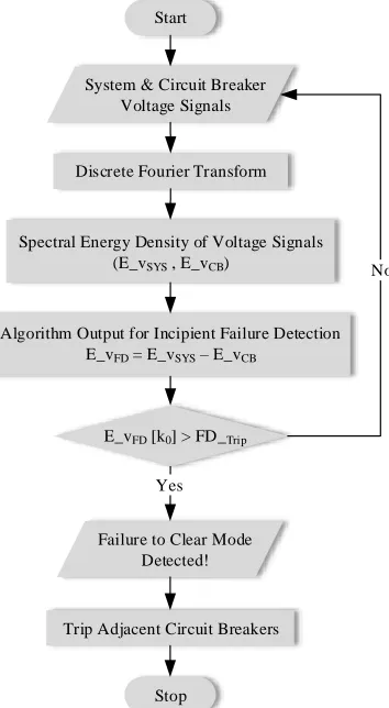
It means that whenever the energy density of the CB voltage signal computed by DFT at the fundamental frequency becomes less than the incipient FD trip level, the algorithm output at the system fundamental frequency exceeds the FD trip level. This indicates that the CB arcing time has exceeded the MPAT and therefore a failure to clear mode of CB has occurred. Thus, the original CB needs inspection or maintenance. In this situation, the algorithm immediately initiates a remote trip command for adjacent CBs to isolate the defected CB and clear the fault. The flowchart of the proposed algorithm is shown in Fig. 1.
III. COMPUTER SIMULATION STUDIES
A topology for studying short line faults (SLFs) is simulated by the electro-magnetic transient program-restructured version (EMTP-RV) [13]. The source side consists of a voltage source with reactance, a transient recovery voltage (TRV) branch, and a time delay capacitance. A constant parameter (CP) line model connects the source side to the CB model. The Cassie-Mayr arc model [14] is used to represent the CB non-linear arc resistance during each interruption. In addition, a controlling TRV branch is utilized in parallel with the arc conductance. The combination of the arc resistance and TRV branch represents a CB model. A time delay capacitance and a CP line model are at the load side of the SLF circuit. The SLF circuit diagram is shown in Fig. 2 for single-phase study.
Start
System & Circuit Breaker Voltage Signals
Discrete Fourier Transform
Algorithm Output for Incipient Failure Detection
E_vFD = E_vSYS – E_vCB
E_vFD [k0] > FD_Trip
Stop
No
Yes
Spectral Energy Density of Voltage Signals (E_vSYS , E_vCB)
Failure to Clear Mode Detected!
[image:3.612.91.268.52.374.2]Trip Adjacent Circuit Breakers
Fig. 1. Flowchart of the proposed FD algorithm for CBs.
a rated voltage of 36 kV as three-phase. The RMS value of the single-phase rated voltage of CB has been defined as the voltage base value, which is 20.78 kV or 1 (pu). On the other hand, the RMS value of the rated current of CB has been defined as the current base value, which is 1250 A or 1 (pu). The parameters of the CP tie-line models are mentioned in Table II [16]. Table III shows the Cassie-Mayr arc constant parameters used for the gas-insulated type CB investigated in this research [17]. The arc parameters of CB depend on the interrupting medium, i.e., air, oil, gas, or vacuum type insulations. The nominal frequency of the studied system is 50 Hz. The simulation sampling frequency is 10 MHz and the length of the simulation study is 100 ms. The number of samples related to DFT has been taken as 2,000 and the frequency resolution of 1 Hz has been considered. The CB receives a trip signal for the interruption of the rated current of CB, 40 ms after the starting of computer simulation studies. The FD trip level has been estimated as 0.5 (pu) using the simulation studies by assuming the MPAT of CB as 15 ms.
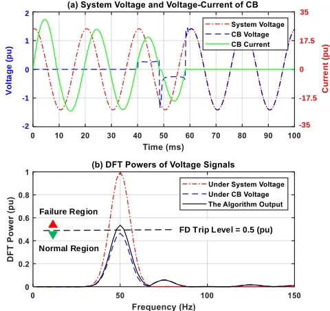
Fig. 3(a) illustrates the system voltage, CB voltage, and CB current associated to the CB rated current for five cycles of the power system frequency. Fig. 3(b) depicts the spectral energy densities of the system and CB voltages around the fundamental frequency. The FD algorithm output for the CB is defined as the difference between the spectral energy densities of the system and CB voltage signals as shown in Fig. 3(b). The arcing time is around 5 ms and the algorithm output is less than the FD trip level. Therefore, the algorithm does not initiate any trip signal in this situation as it is expected.
[image:3.612.316.561.55.197.2] [image:3.612.310.565.72.451.2]Arc
[0, Rnom]
CB Arc Model
1uH
700m 105m
0.5 Ohm 1.6nF
1.1nF 0.022uF
0.5uF 20.78kV 0.1 Ohm 11.2mH
0.1 Ohm 90 Ohm
CB Arc-Based Model
+
R1 + L1
+
C1 +C2
+
R3 CP +
TLM1
+
R4
+
C3
+
C4 R5 +
+ AC1
CP +
TLM2 +
L2
+
G
+
R2
Fig. 2. A SLF circuit for studying the CB switching behaviours. TABLE I. TECHNICAL SPECIFICATIONS OF THE CB[13]
Technical features Description CB type HD4 (MV Gas-Insulated)
Rated voltage 36 kV
Rated current 1250 A
Rated average power 45 MVA
Rated breaking capacity 1247 MVA
Rated frequency 50/60 Hz
Rated breaking current 20 kA RMS Rated making current 50 kA PEAK Maximum permissible arcing time 15 ms
TABLE II. CONSTANT PARAMETERS OF THE SIMULATED LINES [13]
Line Parameters TLM1 TLM2
Line length 105 m 700 m
Resistance 0.0003 Ω/m 0.0003 Ω/m Characteristic impedance 260 Ω 450 Ω
Propagation speed 2.9E+8 m/s 2.9E+8 m/s TABLE III. ARC CONSTANT PARAMETERS OF THE SIMULATED CB[13]
Arc Model Parameters Cassie Model Mayr Model Time constant (τc , τm) 12 µs 4 µs
Constant power loss (P0) - 2 MW
Constant voltage (v0) 5 kV -
Initial conductance (g0) 1000 S 1000 S
Fig. 4(a) shows the same types of voltage and current signals where the CB interrupts the rated breaking current. The current is dramatically increased compared to the rated current of CB. Therefore, the CB arcing time is also increased to around 9 ms. Fig. 4(b) shows the response of the algorithm to this case study. The arcing time is still less than the MPAT, thus the algorithm output also does not go beyond the FD trip level. Therefore, the algorithm does not initiate any trip signal.
Fig. 5(a) shows the same types of voltage and current signals where the CB opens a 16 kA SLF current with an arc restrike originated from the CB worn contacts. Because of the restrike, the arcing time is increased to 13 ms that is greater than a half cycle of the system frequency. Fig. 5(b) depicts the response of the algorithm to this condition. Although there is an arc restrike in this case, the arcing time is lower than the MPAT. This means that the condition for incipient FD is not met yet. Therefore, the algorithm output does not exceed the FD trip level and similar to the previous case studies, the FD algorithm does not initiate any remote trip command as it is expected.
FD Trip Level = 0.5 (pu) Failure Region
Normal Region
V
ol
ta
ge
(
pu
)
1.5
1
-1 0
-0.5 0.5
-1.5
C
urr
e
nt
(
pu
)
1.5
1
-1 0
-0.5 0.5
[image:4.612.58.296.49.276.2]-1.5
Fig. 3. (a) Interruption of the rated current of CB, (b) Response of the proposed algorithm to a permissible arc duration of 5 ms.
FD Trip Level = 0.5 (pu) Failure Region
Normal Region 2
-1 0 1
-2
C
urr
e
nt
(
pu
)
30
15
0
-15
-30
V
ol
ta
ge
(
pu
[image:4.612.320.560.50.276.2])
Fig. 4. (a) Interruption of the CB rated breaking current, (b) Response of the proposed algorithm to a permissible arc duration of 9 ms.
Therefore, this condition must be treated as an incipient failure of CB. Fig. 6(b) illustrates the response of the algorithm to this case. The algorithm output exceeds the FD trip level. Therefore, the algorithm detects it as a failure to clear mode. In this status, the algorithm immediately issues a trip signal for adjacent CBs to isolate the faulty CB and clear the fault if it is persistent.
Considering the above-mentioned case studies, the proposed algorithm shows a good performance in identifying a failure to clear mode of CB immediately after the arcing time exceeds the MPAT of CB. This situation is identified whenever the spectral energy density of CB voltage signal goes below the half per unit of its normal value around the fundamental frequency. The FD trip level is calculated according the MPAT value, thus it could
FD Trip Level = 0.5 (pu) Failure Region
Normal Region 2
-1 0 1
-2
C
u
rr
e
n
t
(pu
)
24
12
0
-12
-24
V
o
lt
a
g
e
(
pu
[image:4.612.61.294.320.548.2])
Fig. 5. (a) Interruption of a 16 kA SLF current with an arc restikre due to worn contacts, (b) Response of the proposed algorithm to a permissible arc duration of 13 ms.
FD Trip Level = 0.5 (pu) Failure Region
Normal Region 2
-1 0 1
-2
C
u
rr
e
n
t
(pu
)
35
17.5
0
-17.5
-35
V
ol
ta
ge
(
pu
)
Fig. 6. (a) Interruption of a 25 kA SLF current with an arc restikre originated by worn contacts, (b) Response of the proposed algorithm to a non-permissible arc duration of 19 ms.
TABLE IV. ALGORITHM OUTPUTS FOR THE CB ASSOCIATED TO VARIOUS INTERRUPTED CURRENTS OBTAINED FROM THE SIMULATION STUDIES Case
No. Interrupted Current
Arcing Time
Algorithm Output
[image:4.612.321.561.322.548.2] [image:4.612.312.564.608.670.2]the FD trip level using simulation study by knowing the MPAT value and parameters of CB. After finding the FD trip level, the algorithm will be ready for real-time implementation.
Table IV lists the values of the algorithm outputs relating to different interrupted currents taken from the simulation studies. For the first three case studies, the values of algorithm output are less than the FD trip level. Therefore, the algorithm does not initiate any trip signal. However, for the last case, the algorithm output exceeds the FD trip level. Therefore, the algorithm issues a trip command that means a failure to clear mode has occurred, thus the CB requires inspection or maintenance. The trip signal is initiated immediately for adjacent CBs after two cycles of the system frequency following the CB interruption.
IV. REAL-TIME TEST STUDIES
Practical measurements are used to analyze the performance of the proposed algorithm. Therefore, the instantaneous system and CB voltage signals are measured using real-time sampling. These voltage signals are acquired from the same gas-insulated CB noted in part III. The data acquisition system has a sampling frequency of 50 kHz with 100 ms measurement length. The CB receives a trip signal 20 ms following the initiation of the test to interrupt the current flow. The FD trip level is considered as 0.5 (pu), which is assumed the same as obtained in section III.
Fig. 7(a) displays the instantaneous measurements of system voltage, CB voltage, and CB current signals for the interruption of the rated current of CB. In this situation, the measured arcing time is around 5.2 ms. Fig. 7(b) shows the real-time response of the algorithm to this test case. As it can be seen in this figure, the arcing time is still much less than the MPAT. Therefore, the algorithm output is below the FD trip level. Thus, the algorithm does not produce any trip signal as it is expected.
Fig. 8(a) depicts the same measurements for the interruption of the CB rated breaking current. For this case, the arcing time is measured as 8.6 ms. Fig. 8(b) depicts the real-time response of the FD algorithm to this condition. Obviously, the calculated arcing time is still less than the MPAT of CB, which means the CB has operated with an acceptable arcing limit. Therefore, the algorithm output does not exceed the FD trip level and the FD algorithm does not initiate any trip command.
Fig. 9(a) displays the same measurements for an interruption of a 16 kA SLF current with an arc restrike originated from CB worn contacts. An arc restrike occurs if the physical separation of CB contacts cannot extinguish an electric arc in a half cycle of the power system frequency. In this situation, the arcing time is measured as 12.4 ms. Fig. 9(b) depicts the real-time response of the algorithm to this case. The arcing time of CB is increased compared to previous test cases, but it is still lower the MPAT. For the same reason, the algorithm output is lower than the FD trip level which shows an acceptable arcing time. Therefore, the algorithm does not produce any remote trip signal and measures the voltage signals of the next interruption.
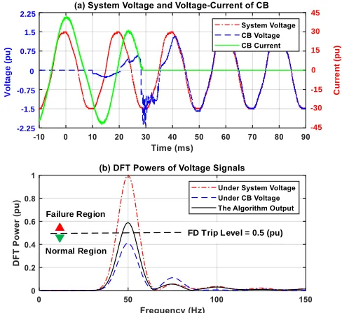
Fig. 10(a) illustrates the same measured signals related to an interruption of a 25 kA SLF current with one arc restrike caused by excessive contact wear. For this case study, the arcing time is measured as 18.8 ms. Fig. 10(b) shows the real-time response of the proposed algorithm under this test. The arcing duration
has increased compared to the previous case studies and now it is greater than the MPAT. The algorithm output exceeds the FD trip level, thus the algorithm immediately issues a trip signal for adjacent CBs, indicating that a failure to clear mode of CB has occurred. This situation indicates that the CB needs inspection or maintenance.
Table V lists the quantities of the algorithm outputs relating to different interrupted currents taken from the test studies. For the first three cases, the values of algorithm output are less than the FD trip level. Therefore, the algorithm does not initiate any trip signal. However, for the last case, the amount of algorithm output goes beyond the FD trip level. Therefore, the algorithm issues a remote trip signal, which means a failure to clear mode of CB has occurred. This shows that the CB requires inspection or maintenance. The remote trip signal is initiated immediately to trip adjacent CBs right after two cycles of the power system frequency following the interruption of CB. By considering the values of algorithm output in Tables IV and V, it is obvious that the results obtained from the computer simulation and real-time test studies are following the same trend. Thereby, the outcomes of practical measurements validate the results obtained from the simulation studies.
It is worth mentioning that in case of having a different phase angle of tripping to current zero, the time of arcing initiation in the first half period of current interruption would change, which implies a different arcing time in the first half cycle. The worst-case scenario of current interruption in the first half cycle occurs when the current flow is interrupted right after the current signal crosses zero. In this situation, the arcing time could increase to 10 ms at maximum. However, the MPAT of the CB used in this research is 15 ms and thereby at least one arc restrike is required to reach the MPAT. Nevertheless, the DFT power associated to the MPAT would remain constant regardless of the phase angle of tripping to current zero. The FD trip level solely depends on the MPAT of CBs, which is the duration of arcing event and not the arcing initiation time. Therefore, the phase angle of tripping to current zero cannot influence the FD trip level. Moreover, the proposed FD trip level is not affected by other system properties as well, because it utilizes the voltage measurement across CB's input and output terminals, which provides it with a component-based architecture rather than a system-component-based one.
In most of electric substations, there is at least one potential transformer (PT) or capacitive voltage transformer (CVT) as a voltage-measuring device already installed on one side of CBs. Therefore, by installing only one more voltage measurement on the other side of CBs, the algorithm would become easily viable and practical, which has been already verified through the real-time test studies in this section.
V. CONCLUSION
FD Trip Level = 0.5 (pu) Failure Region
Normal Region
V
ol
ta
ge
(
pu
)
1.5
1
-1 0
-0.5 0.5
-1.5
C
urr
e
nt
(
pu
)
1.5
1
-1 0
-0.5 0.5
[image:6.612.61.295.50.275.2]-1.5
Fig. 7. (a) Measured system voltage and voltage-current signals of CB during an interruption of the rated current of CB (b) Real-time response of the proposed algorithm to a permissible arc duration of 5.2 ms.
FD Trip Level = 0.5 (pu) Failure Region
Normal Region
V
ol
ta
ge
(
pu
)
2.25
1.5
-0.75 0
-1.5 0.75
-2.25
C
u
rr
e
n
t
(pu
)
45
30
-15 0
-30 15
-45
Fig. 8. (a) Measured system voltage and voltage-current signals of CB during an interruption of the CB rated breaking current (b) Real-time response of the proposed algorithm to a permissible arc duration of 8.6 ms.
CB at the fundamental frequency and arcing times of CB. This correlation is utilized to define an incipient FD criteria based on the energy densities calculated by DFT. The difference between the energy densities of the system and CB voltage waveforms is more appropriate than the difference in their amplitudes. The reason is that signals with moderately low amplitude difference possess a much greater difference in their corresponding energy densities. Thus, the energy difference is defined as the proposed algorithm output for CB. Whenever the algorithm output goes beyond the FD trip level that is related to MPAT, the algorithm immediately initiates a trip command for adjacent CBs. This indicates that a failure to clear incident has occurred and thus the original CB needs inspection or maintenance.
FD Trip Level = 0.5 (pu) Failure Region
Normal Region
V
o
lt
a
g
e
(
pu
)
2.25
1.5
-0.75 0
-1.5 0.75
-2.25
C
urr
e
nt
(
pu
)
30
20
-10 0
-20 10
[image:6.612.317.561.50.273.2]-30
Fig. 9. (a) Measured system voltage and voltage-current signals of CB during an interruption of a 16 kA SLF current with an arc restikre due to worn contacts (b) Real-time response of the proposed algorithm to a permissible arc duration of 12.4 ms.
FD Trip Level = 0.5 (pu) Failure Region
Normal Region
V
o
lt
a
g
e
(
pu
)
2.25
1.5
-0.75 0
-1.5 0.75
-2.25
C
u
rr
e
n
t
(pu
)
45
30
-15 0
-30 15
[image:6.612.317.561.321.544.2]-45
Fig. 10.(a) Measured system voltage and voltage-current signals of CB during an interruption of a 25 kA SLF current (b) Real-time response of the proposed algorithm to a non-permissible arc duration of 18.8 ms.
TABLE V. ALGORITHM OUTPUTS OF THE CB ASSOCIATED TO VARIOUS INTERRUPTED CURRENTS OBTAINED FROM THE TEST STUDIES Case
No. Interrupted Current
Arcing Time
Algorithm Output
Protection Output 1 Rated current 5.2 ms 0.1652 (pu) No Trip 2 Rated breaking current 8.6 ms 0.3074 (pu) No Trip 3 16kA with one restrike 12.4 ms 0.4015 (pu) No Trip 4 25kA with one restrike 18.8 ms 0.5890 (pu) Trip
[image:6.612.57.292.321.544.2] [image:6.612.313.564.610.672.2]can be initially calculated using simulation studies and then be utilized during the real-time implementation of the algorithm. The proposed failure protection algorithm is designed to detect failure to clear mode of CB, which is an abnormal arcing status. Therefore, unlike the failure protection algorithms that operate against failure to trip mode of CB, the proposed algorithm does not need to resend a re-trip signal to the original CB whenever a failure to clear mode is identified. The reason is that a failure to clear mode of CB might even take place sometime before an ultimate interruption of CB. Nevertheless, the failure protection algorithm needs to identify this condition as an abnormal arcing and isolate the faulty CB for required inspection or maintenance by sending a trip signal to adjacent CBs.
For any protection algorithm, the first priority is the speed of implementation and identification. Calculation of DFT is often slow and inefficient in practical situations. Thus, the algorithm of fast Fourier transform (FFT), which is a method to decrease the complexity of DFT, can be used to increase the calculation speed of the proposed algorithm. The computation time can be decreased by several orders of magnitude using FFT. This huge improvement leads to the practical execution of DFT.
ACKNOWLEDGMENT
The authors would like to express their sincere appreciation to Czech Technical University (CTU) in Prague for providing the requirements for the studies. This work has been supported by the project of International Mobility of Researchers in CTU, under the project no: CZ.02.2.69/0.0/0.0/16_027/0008465. The authors are also thankful to LVT test laboratory ltd. in Ankara for providing the facilities required for the test studies.
REFERENCES
[1] IEEE Guide for Breaker Failure Protection of Power Circuit Breakers, in
IEEE Std C37.119-2016, pp.1-73, 16 July 2016.
[2] D. S. S. Lee, B. J. Lithgow and R. E. Morrison, "New fault diagnosis of circuit breakers," in IEEE Transactions on Power Delivery, vol. 18, no. 2, pp. 454-459, April 2003.
[3] H. K. Hoidalen and M. Runde, "Continuous monitoring of circuit breakers using vibration analysis," in IEEE Transactions on Power Delivery, vol. 20, no. 4, pp. 2458-2465, Oct. 2005.
[4] Mingzhe Rong, Xiaohua Wang, Wu Yang and Shenli Jia, "Mechanical condition recognition of medium-voltage vacuum circuit breaker based on mechanism dynamic features simulation and ANN," in IEEE
Transactions on Power Delivery, vol. 20, no. 3, pp. 1904-1909, Jul. 2005.
[5] P. J. Moore, "Radiometric measurement of Circuit Breaker interpole switching times," in IEEE Transactions on Power Delivery, vol. 19, no. 3, pp. 987-992, Jul. 2004.
[6] A. A. Razi Kazemi, K. Niayesh and R. Nilchi, "A Probabilistic Model-aided Failure Prediction Approach for Spring-Type Operating Mechanism of High Voltage Circuit Breakers," in IEEE Transactions on Power
Delivery, Early Access, Nov. 2018.
[7] B. Kasztenny, V. Muthukrishnan and T. S. Sidhu, "Enhanced Numerical Breaker Failure Protection," in IEEE Transactions on Power Delivery, vol. 23, no. 4, pp. 1838-1845, Oct. 2008.
[8] V. Muthukrishnan and T. S. Sidhu, "Fast and secure breaker failure detection algorithms," in IET Generation, Transmission & Distribution, vol. 3, no. 2, pp. 198-205, Feb. 2009.
[9] Instruction Manual, Overcurrent Protection Relay, GRE110, Toshiba
Corporation, pp. 68-69, 2010.
[10] F. Jakob, K. Jakob, S. Jones and R. Youngblood, "Use of gas concentration ratios to interpret LTC & OCB dissolved gas data,"
Proc. of Electrical Insulation Conference and Electrical Manufacturing
and Coil Winding Technology Conference (Cat. No.03CH37480),
Indianapolis, Indiana, USA, 2003, pp. 301-304.
[11] K. Niayesh, M. Runde, "Power Switching Components: Theory, Applications and Future Trends," Springer International Publishing, 2017, pp. 13-57.
[12] W. L. Briggs, V. E. Henson, "The DFT: An Owners' Manual for the Discrete Fourier Transform," Society for Industrial and Applied Mathematics, 1995, pp. 15-64.
[13] B. Feizifar and O. Usta, "A Novel Arcing Power-Based Algorithm for Condition Monitoring of Electrical Wear of Circuit Breaker Contacts," in
IEEE Transactions on Power Delivery, Early Access, Nov. 2018.
[14] U. Habedank, "Application of a new arc model for the evaluation of short-circuit breaking tests," IEEE Trans. Power Del., vol. 8, no. 4, pp. 1921-1925, Oct. 1993.
[15] HD4 Gas insulated MV circuit-breakers, ABB, 1VCP000004 - Rev. O, en - Technical catalogue - 2013.06 (HD4)(gs).
[16] E. Haginomori, T. Koshiduka, et. al., "Power System Transient Analysis: Theory and Practice using Simulation Programs (ATP-EMTP)," John Wiley & Sons, Ltd., 2016, pp. 105-130.
[17] R. Thomas, D. Lahaye,C. Vuik, L. van der Sluis, “Simulation of Arc Models with the Block Modelling Method," in Proc. of Int. Conf. on
Power System Transients (IPST2015), Cavtat, Croatia, Jun. 2015.
Behnam Feizifar (M’19) received the Ph.D. degree in electrical engineering from the Istanbul Technical University (ITU), Istanbul, Turkey, in 2018. He is currently a postdoctoral researcher at the Czech Technical University (CTU) in Prague, the Czech Republic, where he has been involved in the condition monitoring and failure detection of circuit breakers, on-load tap-changers, and power transformers. His main research interests include condition monitoring and failure detection in smart grids and analysis of power system transients.
Zdeněk Müller (M’09-SM’13) received the Ph.D. degree in electrical engineering from CTU, the Czech Republic, in 2012. He has been an associate professor at CTU since 2015. In addition, he is a senior member of IEEE PES. His main research interests include intelligent systems for the safe and reliable electrical energy supply in power systems, local automation in transmission systems, mitigation of negative effects of nonlinear dynamic loads, smart grid architecture, optimization of protection systems, and applications of WAMS in transmission systems.