Oscillatory rarefied gas flow inside a three dimensional rectangular cavity
Peng Wang (王朋), Wei Su (苏微), and Yonghao Zhang (张勇豪)a)
James Weir Fluids Laboratory, Department of Mechanical and Aerospace Engineering, University of Strathclyde, Glasgow G1 1XJ, United Kingdom
(Received 15 August 2018; accepted 18 September 2018; published online 19 October 2018)
The oscillatory rarefied gas flow in a three-dimensional (3D) rectangular cavity, which is frequently encountered in micro-electro-mechanical systems, is investigated on the basis of the gas kinetic theory. The effects of the cavity aspect ratio, the cavity depth ratio, and the oscillation frequency of the driving lid on flow characteristics and damping force are systematically studied using the discrete unified gas-kinetic scheme over a broad range of gas rarefactions. For the highly rarefied flow, when the lid oscillates at a low frequency, as a consequence of the strong rarefaction effect, the damping force on the lid in a 3D cavity could even be smaller than that of a corresponding 2D one (i.e., the depth in the lateral direction approaching infinity). This finding contradicts our intuitive understanding that the damping force is expected to be amplified due to the presence of the lateral walls. Meanwhile, when the lid oscillation frequency becomes sufficiently high, due to the effect of gas anti-resonance, the damping force on the oscillating lid will increase again as the depth reduces for the highly rarefied flow. In addition, the gas resonance and anti-resonance found inside the 2D cavity also appear in 3D ones, and the anti-resonance and resonance frequen-cies as a function of the cavity aspect ratio are nearly the same. However, the presence of the lateral walls will suppress their formation: the smaller the depth, the weaker the intensity of the (anti-)resonance. These findings can help to design the structure of the micro-electro-mechanical devices. © 2018 Author(s). All article content, except where otherwise noted, is licensed under a Creative Commons Attribution (CC BY) license (http://creativecommons.org/licenses/by/4.0/).
https://doi.org/10.1063/1.5052253
I. INTRODUCTION
Oscillatory gas flows are frequently encountered in micro-electro-mechanical systems (MEMS),1 including the
inertial sensors and resonators, the actuators, and the micro-accelerometers. With the miniaturization of the device struc-ture, the characteristic dimension is reduced to the micro- and nano-scales, in which the surface-area-to-volume ratio is large and the gas flow is generally rarefied. Therefore, surface effects such as the damping force exerted on the oscillating parts by the rarefied gas should be carefully considered in the design of micro-devices with moving parts.2
When the mean free path (or collision frequency) of gas molecules is comparable or even larger (smaller) than the char-acteristic flow length (oscillation frequency), the traditional Navier-Stokes equations fail, due to the gas rarefaction, which not only causes velocity slip and temperature jump at solid surfaces, but also invalidates the linear constitutive relations for stress and heat flux. The degree of gas rarefaction is nor-mally characterized by the Knudsen number, defined as the ratio of the gas mean free path to the characteristic length. Alternatively, it can also be defined as the ratio of the oscilla-tion frequency and the collision frequency of gas molecules. Due to micro-/nano-scale dimension of MEMS devices, most of them operate in the slip (10−3.Kn.0.1) and early tran-sition regimes (0.1.Kn.1).3,4Instead of the Navier-Stokes
equations, the gas kinetic model should be adopted for rarefied flow analysis.5,6
To date, gas damping in MEMS devices has been inves-tigated using the Boltzmann equation and its kinetic model equations.6Specifically, the one-dimensional (1D) oscillatory
flow has been extensively studied over a wide range of Knud-sen numbers, where analytical solutions are obtained in the limit of near continuum regime (Kn.0.1)3,7and free molec-ular regime (Kn & 10),5,7,8 while in the transition regime (0.1 . Kn . 10), the problem is numerically solved using the direct simulation Monte Carlo (DSMC) method3,8–13 and the discrete velocity method (DVM).4,5,7,14–18For multi-dimensional flows such as the oscillatory gas flow inside a two-dimensional (2D) cavity,17,19,20it is difficult to derive the analytical solution; thus, the flow in all the regimes needs to be solved numerically. However, the DSMC method and DVM are computationally expensive for flows near the hydro-dynamic regime.21 This is due to the well-known intrinsic
limitation that the computational time step and spatial mesh size are required to be smaller than the local mean collision time and the mean free path of gas molecules, respectively, if the free streaming and collisions of gas molecules are dealt with separately.22Particularly, the DSMC is too costly for low-speed flows typically found in MEMS devices. As a result, previous investigations on the oscillatory rarefied gas flows have mainly been restricted in the transition and free molec-ular regimes. In addition, despite the three dimensional (3D) nature of flow in the MEMS devices, a number of simplified
analytical models have often been used to evaluate damping which are typically based on the 1D Couette flow or Stokes flow.23 For an optimal design of oscillatory MEMS devices,
we need an improved understanding of gas dynamics and its effect on damping, which is the main motivation of this study.
In this work, for the first time, the oscillatory rarefied but low-speed gas flow inside a 3D rectangular cavity is inves-tigated on the basis of the Bhatnagar-Gross-Krook (BGK) equation.24In addition to gas rarefaction, the influences on gas dynamics and damping force from various oscillation frequen-cies, aspect ratios, and depth ratios in the lateral direction of a 3D cavity are investigated using the discrete unified gas-kinetic scheme (DUGKS) that handles the streaming and collision simultaneously.25,26The remainder of the paper is organized as follows. We introduce the formulation of the problem as well as the gas-kinetic BGK equation in Sec. II. Computa-tional details are described in Sec.III. The numerical results of the flow field and damping force are presented, compared, and discussed in Sec.IV, which is followed by the conclusions in Sec.V.
II. PROBLEM FORMULATION
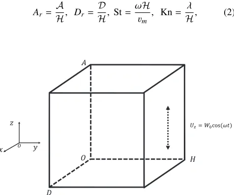
We consider a rarefied gas flow in a 3D rectangular cavity driven by a lid aty=|OH|=H, whereOis the origin of the coordinate, as illustrated in Fig.1. The lid oscillates harmoni-cally in thez-direction with a frequencyω. The time-varying velocity of the oscillating lidUzis given as
Uz(t)=W0 cos(ωt), (1)
whereW0is the amplitude of the oscillating velocity andtis the time. The other walls atx = 0, x = |OD| = D,z = 0, z = |OA| = A, and y = 0 are fixed, and all the walls are isothermal with a temperatureT4.
The problem considered is characterized by the cavity aspect ratioAr, the cavity depth ratioDr, the Strouhal
num-ber St, and the Knudsen numnum-ber Kn, which are, respectively, defined as
Ar =
A H, Dr =
D H, St=
ωH vm
, Kn= λ
[image:2.594.49.287.526.725.2]H, (2)
FIG. 1. Schematic of the oscillatory flow in a 3D rectangular cavity, where Ois the origin of the coordinate.
wherevm = √
2RTwis the most probable molecular velocity withRbeing the specific gas constant. The molecular mean free pathλis related to the gas shear viscosityµas
λ= µ(T =Tw)
p r
πRTw
2 , (3)
wherep=ρRT4is the pressure andρis the density. Note that
the amplitude of the oscillating velocity satisfiesW03mso
that the temperature perturbation is sufficiently small and the flow inside the cavity can be considered as being isothermal. The BGK equation is therefore adopted to describe the flow response. In the absence of external force, it takes the form of24
∂f
∂t +ξ· ∇f =− 1
τf −feq, (4) wheref(x, ξ,t) is the velocity distribution function of gas molecules at the position x = (x,y, z) and the timet, with ξ = (ξx, ξy, ξz) being the molecular velocity. The collision
time τ in Eq. (4) is evaluated from the viscosity µand the pressure byτ=µ/p. The Maxwellian equilibrium distribution functionfeqis given as
feq= ρ
(2πRT)3/2 exp − c2 2RT
!
, (5)
wherec=ξ−Uis the peculiar velocity andU=Ux,Uy,Uz
is the macroscopic flow velocity. The conservative variables
W ≡(ρ,ρU,ρE)Tare calculated from the velocity moments of the velocity distribution function, W = ∫ψfdξ, where ψ =
1,ξ,12ξ2T. Note that for an ideal gas, the temperature is related to the total energy as ρE= 12ρU2+ 3
2ρRT.
The damping force, which is the amplitude of average shear stress acting on the oscillating lid, is an important parameter in the design of MEMS devices. In this work, the average shear stress exerted on the oscillating lid is defined as
¯
Pyz(y=H)=
1 A
A
0
Pyz(y=H,z)dz, (6)
wherePyzis the depth-average shear stress,
Pyz(y=H,z)=
1 D
D
0
Pyz(x,y=H,z)dx, (7)
with the shear stressPyzbeing calculated as
Pyz=
(ξy−Uy)(ξz−Uz)fdξxdξydξz. (8)
Note that the component of average shear stress along the x-axis on the oscillating lid, which is about one order of magnitude smaller than ¯Pyz(y = H), is neglected in this
study.
III. NUMERICAL METHOD
The DUGKS is used to solve the BGK equation,25which has been successfully applied to study the linear and nonlinear oscillatory gas flows inside a 2D rectangular cavity20covering all the flow regimes. The details of the DUGKS for the BGK model can be found in Guoet al.25
spaceξx, ξy, ξz∈(−∞, +∞)
should be properly discretized according to the degree of gas rarefaction. The discretization is associated with a certain quadrature rule to compute the veloc-ity integrals. In the present simulations, the Gauss-Hermit quadratures with 8 points and 16 points are applied in each velocity direction for Kn = 0.01 and Kn = 0.1, respectively, while the continuous molecular velocity space is truncated within [−4√2RTw, 4√2RTw] and discretized by the trape-zoidal rule with 32 non-uniform grid points in each velocity direction when Kn = 1.27,28In terms of the spatial discretiza-tion, a set of non-uniform meshes with Nx ×Ny ×Nz grid
points are adopted in thex,y, andzdirections, respectively, and the mesh resolution is gradually refined from the cavity center to the wall boundaries. The location of each control volume center (xi,yj,zk) is generated byxi = (ζi + ζi+1)/2,
yj= (ζj+ζj+1)/2,zk= (ζk+ζk+1)/2, 0≤i<Nx, 0≤j<Ny,
0≤k<Nz, whereζiis defined as
ζi =
1 2 +
tanh[a(i/N−0.5)]
tanh(a/2) , i=0, 1, 2,. . .,Nx,y,z−1. (9)
Note that the constantadetermines the mesh distribution: the larger the a, the smaller the mesh size near the walls. Here a in the x,y, andzdirections is set to be 2.5, 3.5, and 3.5, respectively. In all the numerical simulations, the height of the cavity is fixed at H = 1. 48 points for Kn = 0.01, and 36 points for Kn = 0.1 and 1 are used per unit length in each direction. Independence of the results on the discretizations of the molecular velocity space and spatial space has been confirmed for these given conditions. Note that the results for Kn>1 will not be presented here as they are very close to the results of Kn = 1, which is similarly reported in our previous work on a 2D cavity.17,20
The computational time step in the DUGKS is solely determined by the Courant-Friedrichs-Lewy (CFL) condi-tion,25∆t=η∆x
min/ξmax, whereηis the CFL number,∆xmin
is the minimum mesh size, andξmaxis the maximum discrete
molecular speed. Note that the DUGKS has distinguished per-formance in robustness.29For instance, when Kn = 0.1, St = 2, Ar = 1, andDr = 1, the change in the amplitude of average
shear stress (6) on the oscillating lid is less than 0.05% when the CFL number varies from 0.01 to 0.8. Therefore, a relatively large CFL number can be used to reduce the compu-tational time. In all the simulations, the CFL numberη≈0.5 is set to satisfyn∆t=π,n∈Z+.
The model accuracy of the DUGKS has been exhaus-tively demonstrated.21,29,30In particular, the DUGKS for the oscillatory rarefied flow has been successfully used in our pre-vious study,20where the results were validated by the solution
of the Boltzmann equation using fast spectral method.17 In
addition, the DUGKS simulation of the 3D lid-driven rarefied cavity flow has also been verified by the DSMC data.31 It is
worthy to emphasize that the primary reason for adopting the DUGKS is that different from the traditional DVM, the grid size in the DUGKS is not necessary to be smaller than the mean free path in the near hydrodynamic regime, which allows the DUGKS to use much fewer grid points than the tradi-tional DVM in describing the slip and continuum flows.21,32,33 For example, when Kn = 0.01, Ar = 1, and Dr = 1, for
St = 0, 2, and 20, with 48 mesh points per unit height, the
maximum change in the amplitude of average shear stress on the oscillating lid is less than 0.2%, when compared to the results of 96 mesh points. With 48 grid points, the aver-age mesh size is about twice of the mean free path of gas molecules.
IV. RESULTS AND DISCUSSION
Numerical simulations covering a wide range of the Knud-sen numbers, the Strouhal numbers, and the aspect and depth ratios of the cavity are performed by the DUGKS, with the diffuse boundary condition for gas-wall interactions.20Note that when the depth ratioDrapproaches infinity, the 3D cavity
is degenerated to 2D ones. Therefore, in this study, the effect of the cavity depth in the lateral direction is of particular inter-est, and the results on the corresponding 2D cavity are also included to show the 3D effect.
A. Flow characteristics
The flow characteristics inside the cavity is investigated under two typical Knudsen numbers of Kn = 0.1 and 1 and two typical Strouhal numbers of St = 1 and 3. We are only interested in the results that have already reached the periodic “steady-state,” that is, the solution at the next oscillation period will be exactly the same as the previous one. The results for the steady lid-driven cavity flow, i.e., St = 0, are also included for comparison. The dimension of the cavity is set asAr=Dr= 1
unless otherwise stated. Since the velocity amplitude of the oscillation is far smaller than the sound speed, the flow field inside the cavity is symmetrical along the cross sections of x = 0.5Dandz = 0.5A. Therefore, flow properties in one-quarter (f0,D2g×[0,H]×f0,A2g) of the cavity are taken into account. Note that thex-component velocityUxis not provided
here as its value is about one order of magnitude smaller than the other two components.
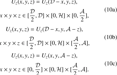
Figure2shows thez-component velocityUzinside
one-quarter of the cavity, whileUzin the rest of the cavity can be
obtained as
Uz(x,y,z)=Uz(D−x,y,z),
x×y×z∈[D
2,D]×[0,H]×[0, A
2],
(10a)
Uz(x,y,z)=Uz(D−x,y,A−z),
x×y×z∈[D
2,D]×[0,H]×[ A
2,A],
(10b)
Uz(x,y,z)=Uz(x,y,A−z),
x×y×z∈[0,D
2]×[0,H]×[ A
2,A].
(10c)
Strong movement of the flow can mainly be seen near the oscillating plane; specifically, the maximumUz occurs in the
center of the oscillating plate. Bearing in mind that when Dr → ∞, the contourlines on the cross sections
perpendic-ular to the y-axis should be a set of lines parallel to the x-axis. As the depth ratio decreases, the role of the lat-eral wall will be enhanced. As a result, when a finite depth ratio (e.g., Dr = 1) is applied, Uz on the oscillating lid
[image:3.594.354.550.512.637.2]FIG. 2. Contours of the flow velocityUzwhen Kn = 0.1 (top row) and Kn = 1 (bottom row), with St = 0, 1, and 3 (from left to right column). HereAr=Dr= 1
andωt/2π= 0. Note that due to symmetry, only one-quarter of the cavity is shown.
due to the friction from the lateral wall ofx= 0; see Fig.2. In addition, contourlines ofUzon the oscillating lid for Kn = 1
is more flattened than those of Kn = 0.1, due to the weaker resistance from the walls for a larger Kn. That is to say, the effect of 3D structure is more visible for a smaller Kn. The velocityUz on the oscillating lid for Kn = 0.1 is larger than
that of Kn = 1, because of the smaller slip velocity (differ-ence between the wall speed and the gas flow velocity) for a smaller Kn.
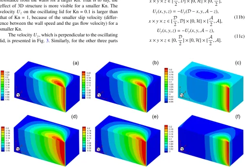
The velocityUy, which is perpendicular to the oscillating
lid, is presented in Fig.3. Similarly, for the other three parts
of the cavity,Uycan be computed as
Uy(x,y,z)=Uy(D−x,y,z),
x×y×z∈[D
2,D]×[0,H]×[0, A
2],
(11a)
Uy(x,y,z)=−Uy(D−x,y,A−z),
x×y×z∈[D
2,D]×[0,H]×[ A
2,A],
(11b)
Uy(x,y,z)=−Uy(x,y,A−z),
x×y×z∈[0,D
2]×[0,H]×[ A
2,A].
(11c)
FIG. 3. Contours of the flow velocityUyin one-quarter of the cavity when Kn = 0.1 (top row) and Kn = 1 (bottom row), with St = 0, 1, and 3 (from left to right
[image:4.594.45.551.381.725.2]For all the Strouhal numbers, the maximumUyemerges at the
joint corner of planes aty = Handz= 0. As St increases, the region in which the gas flow is disturbed by the moving lid is squeezed toward the joint corner, and when Kn = 0.1 and St = 3, the negativeUy appears. In addition, due to the
presence of lateral walls,Uyis decreased from the bulk region
to the boundaries along thexaxis. Finally, as expected, the variation of Uy inside the cavity is much smaller than that
ofUz.
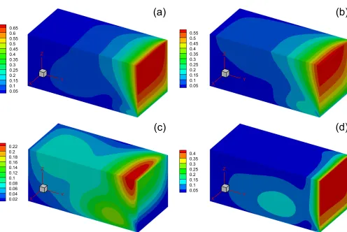
Figure4shows the evolution of gas flow velocity
magni-tude ( q
Ux2+Uy2+Uz2) inside one-quarter of the cavity during
the first half oscillation period for Kn = 0.1 and St = 3, with Ar = Dr = 1. The distribution of the velocity
magni-tude in the next half period is the same. Whenωt = 0 and Uz =W0, the maximum velocity magnitude is located near the oscillating lid; see Fig. 4(a). As the velocity of the lid is reduced to
√
2W0/2 atωt = 0.25π, the perturbation from the oscillating lid has penetrated into the deep cavity. When Uz = 0 at ωt = 0.5π, the flow velocity at the oscillating
lid falls back to zero, but the maximum magnitude appears away from the driven lid. When the oscillating velocity is Uz =−
√
2W0/2 atωt= 0.75π, the intense movement is back to the oscillating lid. Nevertheless, the strong flow motion always occurs near the oscillating plane during the whole period.
B. Damping force on the oscillating plane
1. The shear stress on the oscillating plane
The shear stressPyzexerted on the oscillating lid as
cal-culated by Eq.(8)is depicted in Fig.5, whereAr = 1,Dr= 1,
andωt/2π= 0. The results are similar for other aspect and depth ratios. In the limit of the depth ratio approaching infin-ity, the flow pattern inside the cavity is approximately two dimensional; hence, the contourlines should be parallel to the x-axis. For a finite depth ratio, however, due to the presence of the lateral walls,|Pyz|is expected to be enhanced. It is the case
for Kn = 0.1 with St = 1 and 3, as shown in Figs.5(a)and5(b), respectively, where|Pyz|is increased from the bulk region to
the lateral walls along thex-axis. However, for Kn = 1, the sit-uation is reversed: when St = 1 [see Fig.5(c)],|Pyz|declines
from the bulk region to the lateral wall. Interestingly, when St increases to 3, the|Pyz| becomes larger again toward the
lateral wall [see Fig.5(d)], which is the same as the case of Kn = 0.1. The reason responsible to this intriguing phenomenon will be discussed in detail in the Sec.IV B 3. In addition, the variation ofPyzon the oscillating lid when Kn = 0.1 is about
three times of that for Kn = 1.
2. The depth average shear stress
The absolute value of depth-average shear stress |Pyz| on
[image:5.594.48.544.389.721.2]the oscillating plane along the z-axis is shown in Fig.6 for
FIG. 4. Evolution of the velocity magnitude in one-quarter of the cavity for Kn = 0.1, St = 3, andAr=Dr= 1: (a)ωt= 0; (b)ωt= 0.25π; (c)ωt= 0.5π; and
FIG. 5. Contour of the shear stressPyzon the oscillating planey=Hfor (a) Kn = 0.1, St = 1; (b) Kn = 0.1, St = 3; (c) Kn = 1, St = 1; and (d) Kn = 1, St = 3, whereAr=Dr= 1 andωt/2π= 0. The half of planey=His presented due to the symmetry along the cross sectionx= 0.5.
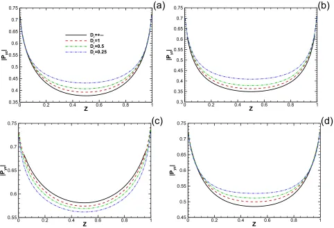
FIG. 6. The absolute value of the depth-average shear stress |Pyz|, as defined in Eq.(7), on the oscillating lid when (a) Kn = 0.1, St = 1; (b) Kn = 0.1, St = 3; (c)
[image:6.594.57.539.392.721.2]Ar = 1 with differentDr. The results forDr=∞, at which the
3D cavity degenerates to 2D, are also included for comparison. At both the side walls, |Pyz| reaches the maximum and then
reduces to the minimum in the middle of the cavity along the z-axis. As the depth ratio increases, |Pyz| decreases and
eventually approaches the value whenDr=∞. However, this
is not the case for Kn = 1 and St = 1 [see Fig.6(c)], where |Pyz| increases with the depth ratio. This is a consequence of
the two competing effects of Kn and St on |Pyz|, as shown in
Fig.5.
3. The damping force on the oscillating plane
In this section, we consider the damping force, i.e., the amplitude of average shear stress on the oscillating plane. First, we try to analyze the behavior of damping force in the limit ofω→ ∞. In this case, binary collisions of gas molecules are negligible7because the oscillation frequencyωis much larger than the mean collision frequency. As a consequence, Eq.(4)
is degenerated to the collisionless Boltzmann equation, ∂f
∂t +ξx
∂f ∂x +ξy
∂f ∂y+ξz
∂f
∂z =0. (12) In addition, due to small amplitude of the oscillating velocity, all the flow properties oscillate around their equilibrium values with the same frequencyω as the oscillation lid. Thus, the velocity distribution function can be expressed as
f(x,y,z,t,ξ)=feq+<
exp(iωt)f0(x,y,z,ξ)W
0, (13)
where the equation forf0is independent of time,
iStf0+ξx
∂f0 ∂x +ξy
∂f0 ∂y +ξz
∂f0
∂z =0. (14) Integrating(14)with respect toxandzon the oscillating plane, one can obtain
iStg+ξy
∂g ∂y =ξx
f0
(x=0)−f0 (x=D) D
+ξz
f0(z=0)−f0(x=A)
A , (15)
whereg=∫0D∫
A
0 f0dxdz/DAis the average velocity distribu-tion funcdistribu-tion. As stated above, for this linear oscilladistribu-tion, the distribution functions on the oscillating plane are symmetric along the centerlines so that the right-hand side of (15)can be neglected. Hence together with the diffuse boundary con-dition,20 the analytical solution of the amplitude of average
shear stress on the oscillating lid can be easily obtained,17
which is equal to 1/√π ≈0.564. From this analysis, we can also learn that the amplitude of average shear stress in the high oscillating frequency limit is independent of the aspect and depth ratios of the cavity, which will be numerically verified below.
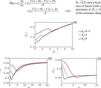
Figure7depicts the damping force|P¯yz|on the
oscillat-ing lid as a function of the Strouhal number, where the depth ratioDr= 0.5. The results are presented at three typical
Knud-sen numbers, i.e., Kn = 0.01, 0.1, and 1. It is observed that the change in|P¯yz|with respect to St for a finite depth ratio possesses a similar behavior to that whenDr =∞.17,20First, |P¯yz| on the oscillating lid increases as the aspect ratio Ar
becomes smaller. Second, |P¯yz| changes non-monotonically
with respect to St. Finally, the variation of|P¯yz|for Kn = 0.01
is more complicated than those at larger Knudsen num-bers. When Kn = 0.01, |P¯yz| will not approach the limit of
1/√π but increases with St at moderately high frequencies (St<50).
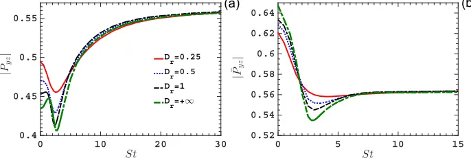
However, the lateral walls could have a manifest impact on the damping force exerted on the oscillating plate. Figure8
shows|P¯yz|as a function of St for two typical Knudsen
num-bers, Kn = 0.1 and 1, with different values of Dr. When
Kn = 0.1 and Dr = 0.25, as St increases, |P¯yz| first declines
to a local minimum at St ≈2.5 and then grows toward the limiting value of 1/√π at the high frequency; see Fig.8(a). However, whenDr =∞, an additional local maximum|P¯yz|
emerges at St ≈ 1.17,20 As the depth ratio is decreased to
Dr= 0.5, such a local peak disappears. That is to say, the
pres-ence of lateral walls could suppress the formation of the local maximum of|P¯yz|. On the other hand, we note that the value
[image:7.594.50.392.451.749.2]of the minimum damping force increases with decreasingDr.
FIG. 7. The amplitude of average shear stress on the oscillating lid as a function of St for (a) Kn = 0.01, (b) Kn = 0.1, and (c) Kn = 1, withDr= 0.5 andAr= 0.5,
FIG. 8. The amplitude of average shear stress on the oscillating lid as a func-tion of St for (a) Kn = 0.1 and (b) Kn = 1, withAr= 1 andDr= 0.25, 0.5, 1,
and∞.
In fact, the local maximum and minimum of |P¯yz| are due to the gas resonance and anti-resonance, respectively, which will be discussed later. From Fig. 8, we can also find that irrespective of the depth ratio, all |P¯yz| approach
the limit of 1/√π when the oscillation frequency is suffi-ciently high, which agrees well with the above theoretical analysis. In addition, the depth ratio seems to have limited effect on the critical Strouhal number (at which the local minimum occurs), which will be theoretically analyzed in SubsectionIV C.
Furthermore, when Kn = 0.1, asDrincreases,|P¯yz|
gen-erally declines toward the value in the limit of Dr =∞. For
Kn = 1 and St . 2, however, the situation is reversed: an increase inDrenlarges|P¯yz|on the oscillating lid, which
con-tradicts the intuitive understanding that the presence of the lateral walls is expected to increase the damping force on the oscillating lid. For St &2, an increase inDr will again lead
to a reduction in |P¯yz|on the oscillating lid. These
observa-tions are consistent with the findings presented in Figs.6(c)
and6(d)for Kn = 1 with St = 1 and St = 3, respectively. Note that the results of Kn<0.1 and Kn>1 are similar to those of Kn = 0.1 and Kn = 1, respectively.
We can explain these as follows. We first consider the case of St = 0. It is well-recognized that the shear stress is produced from the cumulation of the hydrodynamic and the rarefied effects. When the Knudsen number is sufficiently small, e.g., Kn1, the intermolecular collisions are rather frequent so that the hydrodynamic part is dominant and the shear stress satisfies the Newton’s constitutive law; that is to say, the value of shear stress on the oscillating lid is merely determined by the difference of the velocities between the oscillating lid and the flow fluid at the oscillating lid, which is expected to be enlarged due to the presence of the lateral walls. Therefore, for the near continuum flows, the shear stress should increase with decreasing the depth ratio. On the other hand, when Kn1, binary collisions of the molecules can be neglected such that the shear stress on the oscillating lid is mainly deter-mined by the direct collision of the gas molecules with the lid surface per unit time. The presence of the lateral walls could interrupt the travel path of gas molecules, which will there-fore reduce the probability of gas molecules colliding with the oscillating lid. Consequently, for the highly rarefied flows, the shear stress on the oscillating lid is expected to decrease with the reduction in the depth ratio. However, as the oscillation frequency increases, the gas anti-resonance emerges, which will increase the damping force on the lid with the reduction in the depth ratio.
C. Scaling law for resonance and anti-resonance frequencies and aspect ratio
The local drop and rise of the damping force in Figs.7
and8can be interpreted qualitatively by the theory of gas anti-resonance and anti-resonance, respectively. For the free molecular flow, the molecules leaving the oscillating lidy=Hwith the most probable velocity vm
=√2RTw nearly parallel to the oscillating lid, hitting the wall ofz=A, then being reflected and hitting the wall of z = 0, and finally returning to the point from which they left, should have traveled a distance of about 2A; sayvmδt ≈2A, whereδt is the traveling time.
Therefore, if
δt=2nπω or (2n−1)π
ω , n∈Z+, (16) molecules leaving and hitting the top lid should have the same (or opposite) phases.
When the velocity distribution functions for molecules leaving and coming back to the oscillating lid are in phase, the velocityUz near the oscillating lid reaches a maximum.
Meanwhile, the average shear stress given by Eq.(6)is min-imum since the molecules leaving and coming back to the lid have oppositey-component molecular velocities. The anti-resonance and anti-resonance refer to the states where the shear stress exerted on the oscillating lid is minimum and maxi-mum, respectively. Equation(16), together with Eq.(2), give the resonance number Strand anti-resonance Strouhal number
Staas
Str≈
(2n−1)π
2Ar
, n∈Z+ (17)
and
Sta≈
nπ Ar
, n∈Z+. (18)
Therefore, the dominant resonance Strouhal number Str ≈
π/2Arand the anti-resonance Strouhal number Sta≈π/Arcan
be obtained by setting n = 1 in Eqs. (17) and (18). Addi-tionally, Eqs. (17)and (18) suggest that the resonance and anti-resonance Strouhal numbers are independent of the depth ratio, which coincides with the observation from Fig.8.
It should be noted that these analyses are for the free molecular flow. As the Knudsen number decreases, binary collisions of molecules become more frequent such that free transport of the gas molecules becomes less likely. There-fore, the real traveling time is larger than 2A/vm, and the
obtained Sta should be smaller than the theoretical value as
FIG. 9. The resonance (anti-resonance) Strouhal number Str(Sta), at which the
average amplitude of shear stress at the oscillating lid is maximum (minimum), as a linear function of the inverse aspect ratio 1/Arfor (a) Kn = 0.1 and 1 and (b)
Kn = 0.01, whenDris set to be 0.5. The
results of 2D in the limit ofDr=∞are
also included for comparison.20
a consequence, resonance is only observed in the flows with small Knudsen numbers, instead of highly rarefied flows, see Fig.7(a), where the oscillation quickly decays due to the large dissipation.
Depending on the inverse aspect ratio, the linear scaling laws for the anti-resonance Strouhal number with Dr = 0.5
are presented in Fig.9(a)for Kn = 0.1 and 1 and Fig.9(b)for Kn = 0.01. The same conclusions can be drawn for other values ofDr. We find that the fitting scaling laws for Kn = 1 are in
good agreement with the theoretical value ofπ/Ar, while for
Kn = 0.1 and 0.01, as analyzed above, the obtained value is smaller than the theoretical one, and the discrepancy becomes more pronounced as the Knudsen number reduces.
The scaling laws for anti-resonance in a 2D cavity,20i.e.,
Dr=∞, are also included in Fig.9. The relative errors between
the 2D and 3D solutions are depicted in Fig.10, which quan-tifies the effect of the 3D structure (i.e., the lateral walls) on the damping. We can see that the reduction in Kn leads to a larger relative difference for a givenAr. For example, the
relative differences for Kn = 1, 0.1, and 0.01 are about 3%, 10%, and 18%, respectively. This is due to the fact that for a given dimension of the cavity, the lateral walls will pro-duce a larger resistance force for the flow with a smaller Kn. In addition, we also notice that for all Kn, an increase inAr
amplifies the relative difference between the 2D and 3D cav-ity results. This is because that with the given Kn andDr, a
[image:9.594.48.286.559.715.2]largerAr results in a longer travel timeδt, see Eq.(16), dur-ing which the transport molecules will be more likely affected
FIG. 10. The relative errorE% for Staor Strbetween the 2D (Dr=∞) and
3D (Dr= 0.5) simulations as a function of the inverse aspect ratio 1/Ar. Here
E= 100kSt(3D)/St(2D)−1k.
by the lateral walls, thus leading to a greater impact of the lateral walls on the gas anti-resonance, as well as the gas resonance.
The gas resonance appears at Kn = 0.01. The linear scaling law for the resonance Strouhal number with respect to the inverse aspect ratio with Dr = 0.5 is presented in
Fig.9(b), which is in reasonable agreement with the theoretical result given by Eq.(17). Similar to that for the anti-resonance, the relative difference between 2D and 3D cavities increases withAr; see Fig.10. In addition, for a relatively largeAr, the
relative difference for Stris even larger than that for Sta, which
indicates that the lateral walls produce a more significant effect on the gas resonance than on the gas anti-resonance. However, the situation is reversed when a smallAris applied.
V. CONCLUSIONS
We have investigated the oscillatory rarefied gas flow in a 3D rectangular cavity. For small Knudsen number, as the depth ratio reduces, the damping force on the oscillating plane grows as expected. However, due to the strong rarefaction effect, this is reversed for a large Knudsen number with a low lid oscillation frequency, that is, the damping force in a 3D oscillatory cavity can even be smaller than that of the corre-sponding 2D cavity (i.e., the depth in the lateral direction of the cavity approaches infinity). Meanwhile, when the oscillation frequency is sufficiently high due to the gas anti-resonance, the damping force can increase again with reduction of the cavity depth for the highly rarefied flow.
One of the features of oscillatory flow is that the damping force exerted on the oscillating lid has local dips and peaks when the oscillation frequency changes. This is due to the anti-resonance and anti-resonance of rarefied gas flows, respectively. It is found that the lateral walls on a 3D cavity suppress the formulation of gas resonance and anti-resonance. Depending on the inverse aspect ratio of the cavity, the linear scaling laws for the anti-resonance and resonance frequencies are obtained from the near hydrodynamic to highly rarefied flows, which are in reasonable agreement with the theoretical values. In addition, the obtained scaling laws are also compared with the solutions of 2D cases, which suggests that reducing the Knudsen number and increasing the aspect ratio of the cavity will enhance the 3D effect on formation of gas resonance and anti-resonance.
resonant damping is identified as a major consideration for the device design and operation to prevent structural damage.
ACKNOWLEDGMENTS
The authors would like to acknowledge Dr. Lei Wu for careful reading of the manuscript and critical comments. This work is financially supported by the UK’s Engineering and Physical Sciences Research Council (EPSRC) under Grant Nos. EP/M021475/1 and EP/L00030X/1.
1C.-M. Ho and Y.-C. Tai, “Micro-electro-mechanical-systems (MEMS) and
fluid flows,”Annu. Rev. Fluid Mech.30, 579–612 (1998).
2A. Beskok and G. Karniadakis,Microflows and Nanoflows:
Fundamen-tals and Simulation, Interdisciplinary Applied Mathematics (Springer, 2005).
3J. H. Park, P. Bahukudumbi, and A. Beskok, “Rarefaction effects on shear
driven oscillatory gas flows: A direct simulation Monte Carlo study in the entire Knudsen regime,”Phys. Fluids16, 317–330 (2004).
4A. Frangi, A. Frezzotti, and S. Lorenzani, “On the application of the BGK
kinetic model to the analysis of gas-structure interactions in MEMS,”
Comput. Struct.85, 810–817 (2007).
5D. Kalempa and F. Sharipov, “Sound propagation through a rarefied gas
confined between source and receptor at arbitrary Knudsen number and sound frequency,”Phys. Fluids21, 103601 (2009).
6F. Sharipov, Rarefied Gas Dynamics: Fundamentals for Research and
Practice(John Wiley & Sons, 2015).
7F. Sharipov and D. Kalempa, “Oscillatory Couette flow at arbitrary
oscilla-tion frequency over the whole range of the Knudsen number,”Microfluid. Nanofluid.4, 363–374 (2008).
8J. H. Park and S. W. Baek, “Investigation of influence of thermal
accommo-dation on oscillating micro-flow,”Int. J. Heat Mass Transfer47, 1313–1323 (2004).
9S. Stefanov, P. Gospodinov, and C. Cercignani, “Monte Carlo simulation
and Navier–Stokes finite difference calculation of unsteady-state rarefied gas flows,”Phys. Fluids10, 289–300 (1998).
10N. G. Hadjiconstantinou, “Sound wave propagation in transition-regime
micro-and nanochannels,”Phys. Fluids14, 802–809 (2002).
11J. H. Park, S. W. Baek, S. J. Kang, and M. J. Yu, “Analysis of thermal slip
in oscillating rarefied flow using DSMC,”Numer. Heat Transfer, Part A42, 647–659 (2002).
12N. G. Hadjiconstantinou and A. L. Garcia, “Molecular simulations of
sound wave propagation in simple gases,”Phys. Fluids13, 1040–1046 (2001).
13D. R. Emerson, X.-J. Gu, S. K. Stefanov, S. Yuhong, and R. W. Barber,
“Non-planar oscillatory shear flow: From the continuum to the free-molecular regime,”Phys. Fluids19, 107105 (2007).
14D. Kalempa and F. Sharipov, “Sound propagation through a rarefied gas.
Influence of the gas–surface interaction,”Int. J. Heat Fluid Flow38, 190–199 (2012).
15T. Doi, “Numerical analysis of oscillatory Couette flow of a rarefied gas
on the basis of the linearized Boltzmann equation,”Vacuum84, 734–737 (2009).
16T. Tsuji and K. Aoki, “Gas motion in a microgap between a stationary plate
and a plate oscillating in its normal direction,”Microfluid. Nanofluid.16, 1033–1045 (2014).
17L. Wu, J. M. Reese, and Y. Zhang, “Oscillatory rarefied gas flow inside
rectangular cavities,”J. Fluid Mech.748, 350–367 (2014).
18D. R. Ladiges and J. E. Sader, “Variational method enabling simplified
solutions to the linearized Boltzmann equation for oscillatory gas flows,”
Phys. Rev. Fluids3, 053401 (2018).
19L. Wu, “Sound propagation through a rarefied gas in rectangular channels,” Phys. Rev. E94, 053110 (2016).
20P. Wang, L. Zhu, W. Su, L. Wu, and Y. Zhang, “Nonlinear oscillatory rarefied
gas flow inside a rectangular cavity,”Phys. Rev. E97, 043103 (2018).
21P. Wang, M. T. Ho, L. Wu, Z. Guo, and Y. Zhang, “A comparative study of
discrete velocity methods for low-speed rarefied gas flows,”Comput. Fluids 161, 33–46 (2017).
22K. Xu,Direct Modeling for Computational Fluid Dynamics: Construction
and Application of Unified Gas-Kinetic Schemes(World Scientific, 2015).
23W. Ye, X. Wang, W. Hemmert, D. Freeman, and J. White, “Air damping in
laterally oscillating microresonators: A numerical and experimental study,”
J. Microelectromech. Syst.12, 557–566 (2003).
24P. L. Bhatnagar, E. P. Gross, and M. Krook, “A model for collision processes
in gases. I. Small amplitude processes in charged and neutral one-component systems,”Phys. Rev.94, 511 (1954).
25Z. Guo, K. Xu, and R. Wang, “Discrete unified gas kinetic scheme for
all Knudsen number flows: Low-speed isothermal case,”Phys. Rev. E88, 033305 (2013).
26Z. Guo, R. Wang, and K. Xu, “Discrete unified gas kinetic scheme for all
Knudsen number flows. II. Thermal compressible case,”Phys. Rev. E91, 033313 (2015).
27L. Wu, J. M. Reese, and Y. Zhang, “Solving the Boltzmann equation
deter-ministically by the fast spectral method: Application to gas microflows,”
J. Fluid Mech.746, 53–84 (2014).
28W. Su, S. Lindsay, H. Liu, and L. Wu, “Comparative study of the
dis-crete velocity and lattice Boltzmann methods for rarefied gas flows through irregular channels,”Phys. Rev. E96, 023309 (2017).
29P. Wang, L. Zhu, Z. Guo, and K. Xu, “A comparative study of LBE and
DUGKS methods for nearly incompressible flows,”Commun. Comput. Phys.17, 657–681 (2015).
30Y. Bo, P. Wang, Z. Guo, and L.-P. Wang, “DUGKS simulations of
three-dimensional Taylor–Green vortex flow and turbulent channel flow,”
Comput. Fluids155, 9–21 (2017).
31L. Zhu, S. Chen, and Z. Guo, “dugksFoam: An open source OpenFOAM
solver for the Boltzmann model equation,”Comput. Phys. Commun.213, 155–164 (2017).
32K. Xu and C. Liu, “A paradigm for modeling and computation of gas
dynamics,”Phys. Fluids29, 026101 (2017).
33L. Yang, C. Shu, J. Wu, and Y. Wang, “Numerical simulation of flows from