ePrints Soton
Copyright © and Moral Rights for this thesis are retained by the author and/or other copyright owners. A copy can be downloaded for personal non-commercial
research or study, without prior permission or charge. This thesis cannot be
reproduced or quoted extensively from without first obtaining permission in writing from the copyright holder/s. The content must not be changed in any way or sold commercially in any format or medium without the formal permission of the
copyright holders.
When referring to this work, full bibliographic details including the author, title, awarding institution and date of the thesis must be given e.g.
FACULTY OF ENGINEERING, SCIENCE &
MATHEMATICS
Optoelectronics Research Centre
Development, characterisation
and analysis of narrow linewidth,
single-frequency DFB fibre lasers
in the 1.5
μ
m - 2
μ
m region
by
Nyuk Yoong Voo
Thesis submitted for the Degree of Doctor of Philosophy
UNIVERSITY OF SOUTHAMPTON
ABSTRACT
FACULTY OF ENGINEERING, SCIENCE & MATHEMATICS OPTOELECTRONICS RESEARCH CENTRE
Doctor of Philosophy
DEVELOPMENT, CHARACTERISATION AND ANALYSIS OF NARROW LINEWIDTH, SINGLE-FREQUENCY DFB FIBRE LASERS IN THE
1.5μm – 2μm REGION by Nyuk Yoong Voo
The main aim of this study was to investigate the anomalous linewidth behaviour of the DFB fibre lasers, as the observed linewidths of these lasers remain far above their predicted theoretical limit based on the Schawlow-Townes linewidth formula. Narrow linewidth, single-frequency fibre lasers are attractive sources for optical coherent communication, wavelength division multiplexing, optical sensors and spectroscopy, as they have kilohertz linewidths, direct compatibility with the fibre network, wavelength tunability and are simple to fabricate. Another aim of the study was to extend the operating wavelength of the fibre DFB lasers around 2 μm, this research was driven by the number of possible applications in areas such as remote gas sensing, laser imaging detection and ranging (LIDAR) and medicine.
Er3+-Yb3+ DFB fibre lasers showed that not only does the laser linewidth deviate from the Schawlow-Townes linewidth formula, by increasing with pump and laser power, but it also varies with the pump configuration. It was found that the backward pumping scheme has the lowest threshold and highest efficiency, while the dual-pumping scheme was the worst in these aspects. The lowest linewidth operation was actually obtained with the dual-pumping configuration. The variations in laser linewidth were 25-40 kHz. Then, the anomalous linewidth was found to be caused by the fundamental thermal noise at low pump power levels and by temperature fluctuations, induced by pump intensity, at higher powers, which in turn leads to refractive index fluctuations and, thus, to the laser frequency jitter. Some of the potential techniques to overcome the linewidth limitations were experimentally investigated and good agreement was observed. The double phase shifts DFB laser showed a reduction in lasing wavelength shift, as compared with the single phase shift design, for similar laser efficiencies. This suggests that the wavelength shift was not only due to the absorbed pump power but was also affected by the signal intensity distribution in the cavity. A 10% decrease in the laser linewidth with the 5 mm apart phase shifts laser was observed in the backward pumping configuration.
List of Contents
Abstract
i
List of Contents
ii
List of Figures
vi
List of Tables
xi
Author’s Declaration
xii
Acknowledgements
xiii
Symbols and Abbreviations
xiv
Chapter 1 Introduction
1
1.1 Developments of single-frequency fibre lasers with Bragg gratings 4
1.2 Applications 8
1.3 Fabrication of gratings inside the fibre 11
1.4 Outline of thesis 12
1.5 References 13
Chapter 2 Background Theory of Fibre DFB Lasers
17
2.1 Operation of DFB lasers 18
2.2 Optimisation of fibre Bragg gratings 19
2.3 General rate equations of laser 23
2.4 Summary 29
Chapter 3 Erbium-Ytterbium Co-doped Fibre DFB Lasers
31
3.1 Review of linewidth of DBR/DFB fibre lasers 32
3.2 Er3+-Yb3+co-doped phosphosilicate fibre 34
3.2.1 Absorption of the fibre used 35
3.3 The structure of the DFB fibre laser 37
3.4 Linewidth and phase noise characteristics of the DFB fibre laser 38
3.4.1 Experimental set-up 39
3.4.2 DFB power characteristics 41
3.4.3 Laser linewidth characteristic 42
3.4.4 Thermal effects of the DFB laser 48
3.4.5 Relative intensity noise of the DFB laser 51
3.4.6 Self-heating effect associated with non-radiative phonon decay 53
3.5 The main cause of excess noise 59
3.5.1 Analytical model of the laser linewidth 59
3.5.2 Pump laser RIN measurement 62
3.5.3 Filter function of the DFB laser measurement 63
3.5.4 Model calculation of the laser linewidth 65
3.5.5 Validation of the model 66
3.6 Possibilities of reducing linewidth broadening 69
3.7 Conclusion 70
3.8 References 71
Chapter 4 Non-Standard DFB Design: A Comparative Study on
Performance
75
4.1 MOPA laser 76
4.1.1 Lasing threshold and output power characteristics 77
4.1.2 Laser linewidth 78
4.1.3 Lasing wavelength 78
4.1.4 RIN of the MOPA laser 79
4.2 Laser performances with different effective cavity lengths 80
4.2.1 Threshold and output power characteristics 82
4.2.3 RIN of lasers 94
4.3 Two discrete π/2 phase shift DFB lasers 97
4.3.1 Threshold and output characteristics 98
4.3.2 Laser linewidth 101
4.3.3 Laser wavelength 103
4.3.4 RIN of the lasers 105
4.4 Conclusion 108
4.5 References 109
Chapter 5 Development of an Improved Efficiency Thulium-doped
DFB Fibre Laser For 2μ
m Applications
111
5.1 Review of pump absorption bands of Tm3+-doped fibre being used 112
5.2 Tm3+-Sb co-doped alumino-silicate fibre 114
5.2.1 Photosensitivity of the fibre 114
5.2.2 Thermal stability of the Sb Bragg grating 117
5.3 The structure of the DFB fibre laser 118
5.4 Experimental set-up and result of the DFB laser 119
5.5 DFB fibre laser with MOPA configuration and result 121
5.6 Intracavity pumping setup and result 124
5.7 Possible applications of the single-frequency DFB fibre laser
at 1.7-2.0μm 126
5.8 Conclusion 129
5.9 References 130
Chapter 6 Holmium-doped DFB/DBR Fibre Laser at 2.1μ
m
129
6.1 Review of pump absorption bands of Ho3+-doped silica fibre lasers
being used 134
6.2 Ho3+-doped alumino-silicate fibre 136
6.2.1 Photosensitivity of the fibre 136
6.2.2 Absorption of the Ho3+-doped fibre 138
6.2.3 Emission of Ho3+-doped fibre 138
6.4 Experimental set-up and result 140
6.5 DBR laser: Experimental set-up and result 144
6.6 Conclusion 146
6.7 References 147
Chapter 7 Conclusions
148
7.1 Subject of this research 148
7.2 This thesis 149
7.3 Future work 153
7.4 References 155
Appendix I
List of Figures
1.1 DFB laser cavity designs (a) uniform non phase shifted, (b) symmetric single
π-phase shifted, (c) asymmetric single π-phase shifted and (d) asymmetric
singleπ-phase shifted step-apodised……….7
1.2 Absorption wavelength of various molecular species present in the atmosphere and environment within the transmission loss of typical fibres and the gain bandwidth of the rare-earth materials [41]……….10
1.3 Phase mask technique with the zero order being suppressed……….12
2.1 Illustration of the laser oscillation in a periodic structure [7]……….18
2.2 Three-level laser scheme [12]……….23
2.3 Energy level of a two-level system where the two levels comprise many sublevels [12]………..25
2.4 Energy-level diagram for the Er3+-Yb3+co-doped system [1]………27
2.5 Simplified energy level diagram of Tm3+system ………..28
2.6 Simplified energy level diagram of Ho3+system………....29
3.1 Structure of the photosensitive Er3+-Yb3+ with an index matching B/Ge/Si cladding [19]………...35
3.2 The measured absorption loss of the Er3+-Yb3+ co-doped fibre in spectral regions (a) 970 - 980 nm and (b) 1400 - 1600 nm ……….36
3.3 A typical transmission spectrum of the feedback grating in Er3+-Yb3+ DFB laser..………...37
3.4 Technique for the formation of polarisation dependent gratings [23]………38
3.5 Schematic of the laser configurations with pump wavelength of 980 nm: (a) backward-, (b) forward-, and (c) dual- pumping configuration………..39
3.6 Schematic diagram showing the linewidth measurement set-up………40
3.7 Threshold and laser output characteristics of the DFB fibre laser for the three pumping configurations ……….42
3.9 Laser intensity profile build-up around the phase shift of the 5-cm long
DFB……….46
3.10 Self-heterodyne rf-spectrum and its theoretical fit using a convolution of a Gaussian and Lorentzian function ……….47
3.11 Lasing wavelength with pump power of dual-pumping scheme for different heat sink temperatures……….49
3.12 Radial temperature profile in the fibre at 100 mW absorbed pump power…50 3.13 Linewidth behaviour with pump power for two different heat sink temperatures………51
3.14 Measured RIN at the relaxation oscillation frequency of the laser for three pumping configurations………..52
3.15 Schematic of the laser pumping configurations pumped at 1480 nm: (a) backward and (b) forward pumping configuration……….54
3.16 Threshold and laser output characteristics pumped at 1480 nm……….55
3.17 3-dB laser linewidth as a function of absorbed pump power at 1480 nm pump wavelength………..56
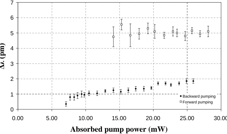
3.18 Laser wavelength shift with the absorbed pump power……….57
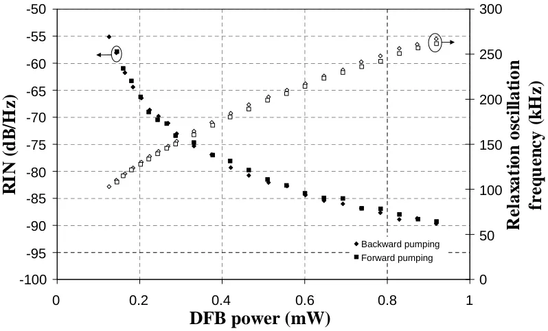
3.19 Measured RIN and ROF of the laser in the backward and forward pumping configurations..………...58
3.20 (a) DFB Laser wavelength λDFB (b) its derivative of the DFB laser wavelength dλDFB/dP versus pump power for the different pump configurations……….60
3.21 Relative pump intensity noise (RIN) as a function of pump power. ……….62
3.22 Spectral broadening Δfmod versus pump modulation frequency (a) dependant on the laser configuration and pump power (b) showing independent of the length of the delay line in the backward pump at 100 mW………64
3.23 Contribution of pump-noise-induced temperature fluctuations to the DFB laser linewidth for the different pump configurations. ………..65
3.24 Threshold and output characteristics of the laser for the three pumping configuration pumped at 975 nm. ………..66
3.25 Laser wavelength shift as a function of pump power. ………...67
3.26 Laser linewidth as a function of pump power. ………...68
4.1 DFB laser + MOPA configuration for high output. ………...76
4.2 MOPA output characteristics of the laser. ……….77
4.3 Measured 3-dB linewidth of the MOPA laser. ………..78
4.4 The MOPA lasing wavelength shifted against pump power. ………79
4.5 Measured RIN at the ROF of the MOPA laser against output power. ……..80
4.6 Coupling coefficients at different phase shift position. ……….81
4.7 Threshold and output power characteristics of the DFB lasers with different grating strengths in (a) backward-, (b) forward-, and (c) dual- pumping configurations. ………...84
4.8 Measured 3-dB laser linewidth of the DFB lasers with different grating strengths in (a) backward-, (b) forward-, and (c) dual- pumping configurations. ………...89
4.9 The laser wavelength shift as function of pump power for the DFB lasers with different grating strength in (a) backward-, (b) forward-, and (c) dual-pumping configurations. ………92
4.10 RIN of the DFB lasers with different grating strengths in (a) backward-, (b) forward-, and (c) dual- pumping configurations. ………...96
4.11 Schematic diagram of a 2 xπ/2 DFB fibre laser. ………...97
4.12 Threshold and power characteristics of the single and two discrete phase shifts DFB structure in (a) backward-, (b) forward- and (c) dual-pumping configuration. ………...100
4.13 The single and two discrete phase shifts lasers linewidth versus DFB power in (a) backward-, (b) forward- and (c) dual- pumping configurations. ……102
4.14 Laser wavelength versus pump power of the single and two discrete phase shifts in (a) backward-, (b) forward- and (c) dual- pumping configurations. ………..105
4.15 The RIN characteristics of the single and two discrete phase shifts laser in (a) backward-, (b) forward- and (c) dual- pumping configurations. ………….107
5.1 Schematic diagram of the Energy-level diagram of Tm3+ in silica [16], showing the pump, absorption, and emission bands. ………...113
5.2 Measured index growth and coupling coefficient at 1597 nm against 244 nm CW-fluence and the calculated coupling coefficient at 1836 nm. ………...116
5.4 Experimental configuration of the single-frequency DFB fibre laser, in a forward pumping scheme. ………119
5.5 Output of the single-frequency DFB fibre laser, at a wavelength of 1836 nm, as a function of absorbed pump power. ………...120
5.6 Experimental setup of DFB laser with MOPA configuration. ……….121
5.7 Single-frequency operation of the DFB fibre laser verified by scanning Fabry-Perot interferometer with FSR of 8.67 GHz. ………122
5.8 Dependence of the output laser power for a constant pump power of 1.4 W on active fibre length. ………...122
5.9 MOPA output of the DFB fibre laser against absorbed pump power at 1565nm, for an active fibre length of 0.5, 1 and 1.85 m. ……….123
5.10 Absorption loss of Tm3+-Sb co-doped fibre .………....124
5.11 Experimental configuration for intracavity pumping. ....……….125
5.12 Experimental spectrum obtained for 100 W of 972 nm pump power/ 25 W of 1552 nm. ………..126
5.13 Calculated absorption spectra for the (3,0) band of NO at 800 K[6]. ……..128
6.1 Simplified three-level energy diagram of Ho3+in silica………...135
6.2 Measured index growth and coupling coefficient at 1597 nm against 244 nm CW-fluence, together with the calculated coupling coefficient at 2140 nm. ………...137
6.3 The measured absorption spectrum of our Ho3+-doped silica fibre. ……....138
6.4 Experimental setup for measuring the emission of our Ho3+-doped silica fibre. ………..139
6.5 The measured emission of Ho3+- doped silica fibre as a function of wavelength. ………..139
6.6 Experimental setup of the5I6pump band of the Ho3+-doped DFB fibre laser. ……….….141
6.7 Spectrum with and without DFB fibre laser at 230 mW pump power…….142
6.8 Experimental set-up for the5I7pump band of Ho3+-doped DFB laser. …...143
6.9 The output spectrum of the Ho3+-doped DFB laser pumped at 5I7band…..144
List of Tables
4.1: The /P and average linewidth of the (a) Backward- (b) Forward- and (c) Dual- pumping configurations. ………..93
Author’s Declaration
I, Nyuk Yoong Voo, declare that this thesis entitled Development, characterisation and analysis of narrow linewidth, single-frequencyDFB fibre lasers in the 1.5 μm
-2μm regionand the work presented in it are my own. I confirm that:
this work was done wholly or mainly while in candidature for a research
degree at the University of Southampton;
where any part of this thesis has previously been submitted for a degree or
any other qualification at this University or any other institution, this has been
clearly stated;
where I have consulted the published work of others, this is always clearly
attributed;
where I have quoted from the work of others, the source is always given. With the exception of such quotations, this thesis is entirely my own work;
I have acknowledged all main sources of help;
where the thesis is based on work done by myself jointly with others, I have
made clear exactly what was done by others and what I have contributed
myself;
parts of this work have been published (see list of publications).
Signed:
Acknowledgements
I acknowledge the support of Brunei Darussalam Government studentship.
I would like to thank my supervisor, Dr. Morten Ibsen, for his supervision and
guidance.
Thanks to Dr. Wei H. Loh for initializing the study of anomalous linewidth in the
DFB fibre lasers. A very special thank you to Dr. Peter Horak for his theoretical
support with the analytical model of the DFB lasers linewidth. Thank you Peter for
many rewarding technical discussions and proofreading some of the thesis chapters.
Thanks to Dr J. K. Sahu and his group for technical discussions and providing the
fibres: Er-Yb, Tm and Ho fibres.
I thank the High Power Fibre Lasers group with whom I have the pleasure of
discussing ideas, borrowing equipment and who generally helped things along:
Christophe, Carl and Pascal. I thank the Advanced Solid State Sources group and
Planar Waveguide Lasers group for borrowing equipment. Thanks also go to my
office-mates for all the fun times we have had! Thanks to Jing and Jingtao for such
an uplifting friendship. Special thanks to Francesca for helping to print, soft bound
and submit the thesis ~ Thank you!Thanks also go to Sue and Clive for providing a
pleasant accommodation and nice meals during my stay there for the viva.
A very special thank you to our postgraduate student mentor, Dr. Eleanor Tarbox, for
kindly allocating her valuable time to correct my countless mistakes in my writing. I
thank Professor Rob Eason and Mrs. Eveline Smith for being so energetic in their
support of the ORC PhD students. Thank also go to Professor J. P. Dakin and his
group for starting my journey in sensors and fibre lasers.
Big thanks to my family and friends for their patience and support throughout my
Symbols and Abbreviations
B/Ge Boron/germanium
Ccr Cross relaxation coefficient
Cup Upconversion coefficient
cv Specific heat capacity of silica
CW Continuous-wave
D Penetration depth
DBR Distributed Bragg reflector
DFB Distributed feedback
Er Erbium
Er-Yb Erbium-Ytterbium
FBG Fibre Bragg grating
g Small signal gain
Ho Holmium
hνP, hνS Pump and signal photon energies respectively
IP, IS Pump and signal photon intensities respectively
kB Boltzmann constant
L Length of grating
Leff Effective cavity length
LIDAR Laser imaging detection and ranging
MOPA Master oscillator power amplifier
NA Numerical aperture
Nd Neodymium
n Refractive index
neff Effective index of the mode
NEr, NYb Concentrations of Er3+and Yb3+respectively
N1, N2and N3 Population density of laser level 1, 2 and 3 respectively
Pavg Average optical power
Pelec Power-spectral density of photocurrent
Pavg(elec) Average power of photocurrent
PZT Piezoelectric transducer
r Reflection coefficient
R Reflection coefficient energy
RIN Relative intensity noise
ROF Relaxation oscillation frequency
Sb Antimony
S(f) Laser spectrum
SF(f) Laser frequency jitter spectrum
T Temperature
T(f) Frequency response of the DFB laser to pump fluctuations
Tm Thulium
UV Ultra-violet
V Effective mode volume
Wij Stimulated transition rates between the i and j levels
WDM Wavelength division multiplexing
Yb Ytterbium
a P
,Pe Absorption and emission cross-section of the pump respectively
a S
,Se Absorption and emission cross-section of the signal respectively
λB Bragg wavelength
κ Coupling coefficient
ρ Density of silica
α Field gain
Δf Laser linewidth
Δn Index modulation change
ΔP Amplitude of the pump fluctuations
ΔP2
Mean square optical intensity fluctuation
Δν Laser frequency
Δνcav Grating linewidth
Г Phase matching
Λ Spatial period of the grating
τEr,τYb Spontaneous emission lifetimes of erbium and ytterbium respectively
2
, 3 Spontaneous emission lifetime of level 2 and 3 respectively
“The beginning of knowledge is the discovery of something we do not understand.”
Chapter 1
Introduction
____________________________________________________________________
Narrow-linewidth, single-frequency lasers are attractive sources for optical coherent
communications, wavelength division multiplexing, optical fibre sensors and
high-resolution spectroscopy. Single-frequency fibre lasers are promising alternatives to
semiconductor lasers as they have kHz linewidths, direct compatibility with the fibre
network, wavelength tunability and are simple to fabricate. The single frequency
operation of fibre lasers has been demonstrated in: fibre ring lasers [1], linear cavity
fibre lasers with a narrow filter [2], distributed Bragg reflector (DBR) fibre lasers [3,
4] and distributed feedback (DFB) fibre lasers [5] and also in the Fabry-Perot type
lasers by making the cavity extremely short <1 mm [6]. The research described here
aims to develop compact sources, with a narrow linewidth, low noise and good
wavelength stability, suitable for high-end applications.
Laser linewidths of≤10 kHz have been reported in the Er3+-doped fibre ring-lasers
[1, 7]. In [1] the single-frequency of the laser was obtained by maintaining the
polarisation of the mode. Single-mode operation in the fibre ring cavity can be
achieved with the Fabry-Perot filter [7]. Lasing is easy to obtain in the fibre
ring-laser with a low Er3+concentration fibre in which the gain medium must be very long
(typically longer than 10 m) to produce enough gain. Owing to the long cavity
closely spaced multiple longitudinal modes. This can severely limit their applications
due to multimode oscillation and mode hopping. In addition, the length of the cavity
is susceptible to thermal drift and this will cause long-term mode hopping, even with
a combination of filters inside the ring-cavity to suppress the mode hopping [8].
Mode hopping can be eliminated by actively stabilising the laser through dithering of
the cavity length using a piezoelectric transducer (PZT) fibre stretcher controlled by
feedback from the output of the laser [9]. However, this solution makes the laser
design become more complex.
Recently, a single-frequency ytterbium (Yb3+) fibre laser was demonstrated based on
a linear cavity in which a narrow bandwidth filter is used to select the single
longitudinal mode and the dual-cascaded fibre Bragg gratings act as an output
coupler [2]. Single-mode operation of this laser was achieved by using a saturable
absorber, a section of unpumped gain fibre, in which counter-propagating waves
formed an interference pattern that generated a dynamic Bragg grating at 1064 nm.
The cavity length of this laser was about 1 m and an output power of 18 mW was
obtained with a pump power of 107 mW at 976 nm. The mode stability of this laser
was limited at high pump power due to the spatial hole burning caused by the high
intensity in the cavity.
One can also obtain single-frequency operation in Fabry-Perot-type lasers by making
the cavity extremely short < 1mm. Single-longitudinal mode operation is obtained,
with the mode spacing in the resonator relatively larger than the gain bandwidth, so
that only one mode acquires sufficient gain to reach lasing threshold. A 100-μm long
erbium-ytterbium (Er3+-Yb3+) phosphate-glass fibre Fabry-Perot laser, operating at
1535 nm was demonstrated with a two-mirror laser resonator design [6]. Due to a
short cavity length, the output power of this laser was very low (~ 20μW).
Robust single-longitudinal mode operation without mode hopping has been
demonstrated in the DBR [3, 4, 10-13] and DFB [5, 14, 15] fibre lasers. Very narrow
laser linewidth of a few tens of kilohertz and a low relative intensity noise of < -140
lasers and linear cavity design. Unlike the ring fibre lasers and linear cavity, in which
the laser wavelength was defined by a filter such as an interference filter [1], a fibre
Fabry-Perot filter [7] or auto-tracking filter [2]. In the DBR and DFB fibre lasers, the
laser wavelength is determined by the ultraviolet (UV) written Bragg gratings and it
can be accurately set to ≤0.1 nm during manufacture and has a low sensitivity to
temperature (~10 pm/K). DBR fibre lasers are only robustly single-frequency
provided that the grating bandwidth is kept below ~0.2 nm and the laser length is
reduced to a few centimetres to increase the axial mode spacing.
DFB fibre lasers integrate a single grating over the entire cavity for feedback and
wavelength determination. The advantage of the geometry of the DFB design, as
compared with the DBR design in which the two Bragg gratings are separated by a
gain section, is that it can be made shorter to provide robust single-mode operation.
In addition, the DFB fibre lasers are more environmentally stable than the DBR fibre
lasers as the thermal response of the Bragg wavelength of the two reflectors of the
DBR varied slightly and also the wavelength of the reflectors varied slightly as a
function of grating exposure. Hence it is this type of DFB fibre laser source that we
consider here and also because the fibre DFB lasers have shown flexibility in the
pumping conditions and pump redundancy by configuring them in a parallel array
[16].
To date, the observed linewidths of these fibre lasers remain far above their
theoretical limit predicted, based on the Schawlow-Townes linewidth formula, to be
just 60 Hz or less [12]. One common suggestion for this excess phase noise is due to
the environmental perturbations, such as external vibration and acoustic noise, to
which the fibre laser may be more susceptible. Experimental investigation of the
linewidth characteristics of the Er3+-Yb3+DFB fibre lasers is conducted to find the
main cause of the excess phase noise. Also, most of the work has been concentrated
in developing the single-frequency fibre lasers at the 1.5μm wavelength region for
applications related to optical communications, to gas sensors and to high resolution
spectroscopy. The development of laser sources operating around the 2 µm
‘eye-safe’ region has also started to gather pace, mainly driven by a number of possible
(LIDAR) and medicine. The single-frequency DFB fibre laser in the 2μm region is
still under development. Therefore, we also aimed to extend the operating
wavelength of the DFB fibre lasers around 2 μm using thulium (Tm) and holmium
(Ho) as the gain medium.
1.1 Developments of the single-frequency fibre lasers
with Bragg gratings
This section gives a brief history of the development of the single-frequency fibre
lasers with Bragg gratings. Short-cavity single-frequency fibre lasers have been a
topic of continued interest since the early work of Ball et al. on erbium-doped
distributed Bragg reflector fibre lasers [3]. Currently, the single-frequency fibre
Bragg grating lasers operating in the spectral region of 1μm have been demonstrated
with ytterbium (Yb3+) and neodymium (Nd3+) as the gain medium. In the 1.5 μm
region, the gain medium used was erbium (Er3+). The single-frequency DFB fibre
lasers operating at ~2μm based on thulium (Tm3+) dopant have been demonstrated.
The advances in the laser cavity designs of the DFB fibre lasers are also included in
this chapter.
Most of the research activities in single-frequency fibre lasers has been concentrated
in the wavelength region around 1.5 μm, as it is the key component of the optical
communication systems such as wavelength division multiplexed (WDM) networks.
The first Er3+-doped DBR silica fibre laser was demonstrated by Ballet al. in 1991
[3]. It consisted of a 50-cm long Er3+-doped fibre with two discrete Bragg grating
reflectors on opposite ends of the fibre. For a robust single-mode operation, the
cavity needs to be sufficiently short so that the mode spacing is comparable to the
grating bandwidth. For a grating bandwidth below ~0.2 nm, it is desired to have a
mode spacing of the order of 10 GHz, i.e. cavity length of the order of 1 cm. The
concentration of the Er3+ is limited by the germanosilicate glass host, so it is
necessary to keep the Er3+ concentration below 100 ppm to reduce ion-pair
cavity length was low and as a result the output power, for a cavity length of only a
few centimetres long, was limited to about 200 μW [10, 11, 14]. This power can be
boosted using the residual pump in the master oscillator power amplifier (MOPA)
configuration [11, 14]. An output power of 60 mW was obtained with a fibre length
of 19-m in a Er3+-doped fibre amplifier [11]. However, the amplified spontaneous
emission from the amplifier increased the output noise. This fundamental problem
was then solved by, Kringlebotn et al., co-doping the Er3+ -doped fibre with Yb3+
[17]. This increases the pump absorption at 980 nm by more than two orders of
magnitude and thus enhances the laser efficiency operation of centimetre long lasers
with relatively low Er3+concentration [4, 17]. The pump excites the Yb3+ions which
then transfer their energy to the Er3+ions by resonant coupling. An output power of
19 mW for 100 mW pump power was achieved with a 2-cm long Er3+-Yb3+-doped
fibre [4]. However, for efficient Er3+-Yb3+ -doped devices, fibres require a
phosphosilicate host glass, which is not photosensitive. Therefore, the UV written
Bragg gratings are unable to be directly written into the fibre. For these lasers, the
Bragg grating reflectors were written into a photosensitive fibre which was then
spliced to the doped fibre, and as a result intra-cavity splice loss was introduced. A
heavily co-doped Er3+-Yb3+fibre laser has also been reported with an output power
of 200 mW, with a pump power of ~850 mW [13]. The laser cavity was based on
two passive fibre Bragg gratings (FBGs) that are fusion spliced to a 2-cm long doped
fibre.
The photosensitivity of the Er3+-Yb3+ -doped fibre can be enhanced by loading the
fibre with hydrogen and nearly 100% reflectivity in the grating was observed by
Kringlebotn et al.and was followed by the first demonstration of DFB fibre laser in
1994 [5]. The feedback grating at 1.5 µm was directly written into a length of 2-cm
Er3+-Yb3+ -doped fibre. The output power of this laser was 3.2 mW, with a slope
efficiency of 5.4%. Then, a DFB fibre laser based on Er3+-Yb3+ co-doped with tin,
(rather than using the hydrogenation technique which increased the fibre losses), to
improve the fibre photosensitivity has been demonstrated [18]. The slope efficiency
of this laser was 11%. A further improvement in the photosensitivity of the Er3+-Yb3+
co-doped fibre has been demonstrated, by L. Dong at el., using a highly
[19]. Both DBR and DFB lasers have been realised with this fibre and have shown
slope efficiencies of 25%. Before the photosensitivity of the Er3+-Yb3+-doped fibre
was enhanced by using the B/Ge cladding, developments were carried out to improve
the laser efficiency in the Er3+-doped fibre by using an intra-cavity pumping scheme
[20] and also by pumping into the 520 nm absorption band [21]. For the intra-cavity
pumping, the DFB laser was placed inside an Yb3+fibre laser, which was used as the
pump source for the DFB laser. A three-fold increase in the output power was
observed as compared with direct 980 nm pumping [20]. Pumping in the 520 nm
absorption band has shown an increase in the slope efficiency of 10% which was an
order of magnitude improvement over that attainable by 980 nm pumping [21].
Research was not only conducted in improving the fibre material for high pump
absorption of Er3+, but also in the designs of the feedback cavity of the DFB fibre
lasers to maximise the laser output. A DFB laser with a uniform grating, i.e. without
a phase shift and with no end reflectors, will operate in two longitudinal modes at
different wavelengths, corresponding to the edges of the grating bandgap and gives
equal output power from both ends [22]. However, single wavelength operation is
required in real practice. In [5] the single-frequency operation of the DFB fibre lasers
has been achieved by using an end reflector to change the round-trip phase shift in
the cavity or by locally heating the grating to slightly increase its refractive index
around that point in order to create the optical phase shift of π/2 such that the
round-trip phase condition is satisfied at the Bragg wavelength. The permanently induced
phase shift in the centre of the grating has been achieved by locally elevating the
background refractive index in the fibre core with additional exposure of UV light
around the centre of the uniform grating [14]. The other techniques to introduce the
phase-shifted gratings were with the moving fibre-scanning beam technique and with
phase masks in which the phase shifts can be incorporated into the grating during the
writing process by simply moving the fibre by an appropriate distance at the desired
time while the UV beam is scanning [23]. The output powers of these lasers are
equally divided at both ends; this is because of the symmetry of the cavity. The laser
wavelength coincided with the Bragg wavelength. For a high performance laser,
from the shorter end [24, 25]. A further improvement in the laser efficiency has been
demonstrated with a step-apodised design in which the position and length of the
effective cavity can be enhanced without impacting the cavity asymmetry, cavity
Q-factor, or the overall laser length [26]. Basically, the step-apodised DFB laser has
employed a step change in the coupling coefficient on either side of the phase shift to
restore the optimum optical feedback. It has shown an increase in the pump-to-signal
conversion of 40% in the Er3+-Yb3+co-doped fibre. The different types of DFB laser
cavity mentioned are shown in Figure 1.1, Pleftand Prightrefer to output powers of the
laser.
[image:26.595.159.481.275.561.2](d)
Figure 1.1: DFB laser cavity designs (a) uniform non phase shifted, (b) symmetric single π-phase shifted, (c) asymmetric singleπ-phase shifted and (d) asymmetric singleπ-phase shifted step-apodised [26].
Other laser wavelengths operating in the 1μm region have been demonstrated with
Nd3+-doped [27] and Yb3+-doped [28] fibre. The cavity feedback of the Nd3+-doped
fibre laser was based on the intra-core Bragg reflectors on the opposite ends of a 4-m
long doped fibre. The output power was ~12 mW with a pump power of 265 mW. In
[28] the DFB fibre laser was a 10-cm long grating, with a UV-inducedπphase shift (a)
(b)
(c)
π
π
π
Pl eft
Pl eft
Pl eft
Pright
Pright
Pright
κ1
in the centre of the grating, written throughout the whole length of the Yb3+-doped
fibre. The maximum power achieved was ~8 mW with a pump power of ~20 mW.
The sources operating around 2 μm also began to develop, driven by a number of
applications such as in LIDAR, sensing applications and medicine. The single
frequency DFB fibre laser operating in the 2 μm region was demonstrated with
Tm3+-doped fibre by S. Aggerat el. two years ago [29]. The laser cavity was 5-cm
long and had an output power of 1 mW with a slope efficiency of 0.2%.
Some applications, as in the wavelength-division multiplexing and sensor systems,
required a continuously tunable wavelength. The single-frequency DBR and DFB
fibre lasers are not restricted by their Bragg grating wavelength, they are capable of
being continuously wavelength tuned, without mode hopping [30-32]. The laser
wavelength tuning techniques used are uniformly stretching [30], compression [31]
and a combination of extension and compression [32]. In the stretching or
compression technique, the change in reflected wavelength from the Bragg reflector
tracks the change in cavity resonance wavelength so that mode hopping is avoided.
The fibre laser was mounted, at both ends, onto a PZT and a maximum wavelength
tuning of 0.72 nm was obtained for maximum stretching. This technique is
mechanically simple to implement but its tuning range is limited by the maximum
range of the PZT as well as the fibre strength. The compression technique has shown
a wavelength tuning of over 32 nm in a DBR fibre laser [31]. In this compression
technique, the fibre laser was fixed by epoxy between two ferrules, one mounted to a
fixed stage and the other to the stepper motor for compression. Three floating
ferrules were placed between the two fixed ferrules and attached to the stepper
motor. The other technique that has been demonstrated was using a combination of
the extension and compression [32]. The DFB fibre laser was embedded in a firm
bendable material and a wavelength tuning range of 27 nm was demonstrated.
1.2 Applications
because of their narrow linewidth, robust single-mode operation, compact in-fibre
design, flexible and accurate wavelength selection in production, as well as easy
tuning of the wavelength. A number of the applications have been illustrated with
these sources.
(a) Optical communication systems
The first data transmission experiment has been demonstrated using an Er3+-doped
DBR fibre laser transmitter [33]. The available laser power was 91 μW and
externally modulated at 2.5 Gbit/s. This permitted data transmission over 654 km,
with Er3+-doped fibre amplifiers to boost the signal power. Even at higher
transmission rates of 5 Gbit/s this has also been demonstrated with an Er3+-doped
DBR fibre laser with a similar output power as in Ref. [33] and the bit-error-rate
(BER) at the 10-15 level has been observed over a distance of 86-km with
non-dispersion shifted transmission fibre [34].
Both DBR and DFB fibre lasers have also been demonstrated in wavelength-division
multiplexing (WDM) systems, in which multiple optical signals are carried on a
single optical fibre for a multiplication in capacity [35-37]. The Er3+-doped DBR
fibre laser with MOPA has been modulated at 2.5 Gbit/s and signals transmitted over
a 475 km long WDM transmission line [35]. Multiplexing of four DFB fibre lasers,
separated in frequency by 100GHz (0.8 nm), on a 10 Gbit/s WDM link has been
demonstrated over a 200 km standard single-mode fibre [36]. A further increase in
channel capacity has been demonstrated by multiplexing eight and sixteen DFB fibre
lasers together to form an 8- and 16-channel WDM transmitter array respectively
[37]. In this setup, the DFB fibre lasers were pumped using a pump redundancy
scheme in which the powers from the pumps are split equally between the fibre
lasers. It will always remain in operation even if one or more pump failures occur.
(b) Acoustic sensors
Optical fibre acoustic sensors have been demonstrated both in air [38] and for
uncoated fibre DFB laser to sense the acoustic-wave motion and the fibre laser’s
frequency shifts induced by it were measured by using a Mach-Zehnder
interferometer. The acoustically induced frequency shifts measured in [38] ranged
from 0.61 MHz/Pa at 100-Hz to 0.34 kHz/Pa at 15 kHz. The use of DBR and DFB
fibre lasers as a hydrophone has been demonstrated [39]. The principle of operation
of the hydrophone is similar to the acoustic air sensor, in which the pressure induced
wavelength shift of the laser is then measured with the interferometer. The fibre
lasers gave a minimum detectable acoustic signal of -69 dB re Pa/√Hz at 1 kHz [39].
Then, three DFB fibre lasers were spliced together on a single fibre to form a
hydrophone array and no optical cross-talk was observed [39].
[image:29.595.171.445.352.612.2](c) Spectroscopic application
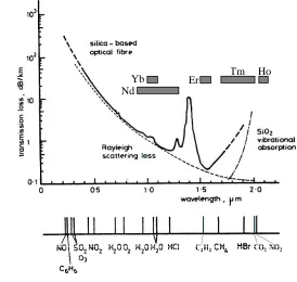
Figure 1.2: Absorption wavelength of various molecular species present in the atmosphere and environment within the transmission loss of typical fibres and the gain bandwidth of the rare-earth materials[40].
Figure 1.2 shows absorption wavelengths of various common gases in the
atmosphere and environment, together with the transmission loss of typical fibres in
Nd
the visible and near infrared regions, in which the associated wavelength can be
covered by the rare-earth doped fibre lasers. The possibility of using a grating-based
fibre laser for the spectroscopic detection of gaseous species has been demonstrated
in [41]. The fibre laser realised was used for the detection of atmospheric water. The
laser cavity was formed by two UV written Bragg gratings at both ends of the Nd3+
-doped fibre. The laser operating wavelength was at 1117.96 nm and tuned around an
absorption line of water molecules at 1118.06 nm.
1.3 Fabrication of gratings inside the fibre
Currently, fibre grating fabrication techniques used for the feedback gratings in the
lasers are holographic [42] and by using the phase mask approaches [43, 44]. In the
holographic method, the gratings are formed, usually in the core of the fibres which
is photosensitive, by irradiating the fibre from the side, with a coherent two-beam
UV interference pattern. The 244-nm UV radiation is split into two equal-intensity
beams and then recombined to produce a periodic interference pattern that writes a
corresponding periodic index grating in the core. The period of the grating depends
on the angle between the two interfering coherent beams. For the phase mask
technique, it allows fibre gratings to be written with a lower coherence UV laser
beam and with better repeatability. The phase mask is a surface relief grating etched,
by a photolithographic technique, in fused silica. In this technique, a phase mask
grating is placed in contact, or nearly in contact, with the fibre. When the UV laser
beam is incident on the mask, it diffracts into the 0, +1 and -1 orders, as seen in
Figure 1.3, where the zero-order is suppressed by the depth of the corrugations in the
phase mask. The +1 and -1 order diffracted beams interfere to produce a periodic
pattern that photoimprints a corresponding grating in the fibre. The period of the
photoimprinted index grating is half of the phase mask grating. For the fabrication of
a phase shifted DFB fibre laser, the uniform phase mask method based on the
moving fibre-scanning beam technique allows the insertion of the phase shift into the
fibre grating [45]. The fibre is mounted on a computer-controlled PZT stage, and it
can move slowly relative to the phase mask, permitting the phase shift to be
Figure 1.3:Phase mask technique with the zero order being suppressed.
1.4 Outline of thesis
Following this introduction chapter, Chapter 2 begins with the basic principles of
fibre DFB lasers with a phase shift.
Chapter 3 studies the linewidth characteristics of the Er3+-Yb3+ DFB fibre laser as
they were found to contradict the Schawlow-Townes linewidth prediction. A few
experiments were conducted to investigate this anomalous laser linewidth. Lastly, an
analytical model was developed to explain the main cause of the excess phase noise
that was due to the temperature fluctuation resulting from the intensity noise of the
pump source. This was followed by the possible techniques that could be used to
avoid this limitation.
The non-standard DFB fibre laser designs were investigated in Chapter 4. Some of
the suggested techniques for the linewidth limitation were experimentally
investigated in this chapter. The laser was operated in the narrow linewidth regime
with low output power and subsequently, operated in the MOPA regime to show that
the characteristics of the laser were still maintained. The other methods were to
investigate the laser linewidth due to different effective cavity lengths by using
coupling coefficients of 100 m-1, 150 m-1 and 200 m-1. Its linewidth was
configuration dependent. We also observed that the laser wavelength shift was Incident UV
Light Beam
Phase Mask Grating
+1st order -1st order
Diffracted Beams
fabricated to increase the effective cavity length of the laser and its performance was
compared with the standard design. The discrete double phase shift lasers were
implemented to modify the intra-cavity intensity and this showed a reduction in
linewidth as well as the lasing wavelength shifting with DFB power or pump power.
From the success in realising the Er3+-Yb3+ DFB fibre lasers, with the same phase
mask technique and DFB structure, it was feasible for us to realise even longer
wavelengths to open a new window for the possible applications of this source. In
Chapter 5, an improved efficiency of the DFB laser at 1.8μm was demonstrated with
the thulium, co-doped with antimony, fibre. The laser output was about 5 mW with a
pump power of 1.4 W at 1565nm. Then, the output was amplified with the MOPA
for high power and a gain of 15 dB was achieved.
In Chapter 6, we aimed to push the laser wavelength even further into the 2.1μm
region with the holmium doped fibre. The laser has been pumped with a Raman fibre
laser at 1119 nm and also the thulium DFB fibre laser. However, no lasing was
observed for either pump source. Then, the DBR fibre laser was set-up and still no
lasing was observed. Some of the reasons causing failure to lase have been discussed.
The final chapter summarises the key results and recommendations for further work.
1.5 References
[1] K. Iwatsuki, H. Okamura, and M. Saruwatari, "Wavelength-tunable single-frequency and single-polarisation Er-doped fibre ring-laser with 1.4 kHz linewidth," Electronics Letters, vol. 26, pp. 2033-2035, 1990.
[2] S. Huang, G. Qin, Y. Feng, A. Shirakawa, M. Musha, and K.-I. Ueda, "Single-frequency fiber laser from linear cavity with loop mirror filter and dual-cascaded FBGs," IEEE Photonics Technology Letters, vol. 17, pp. 1169-1171, 2005.
[3] G. A. Ball, W. W. Morey, and W. H. Glenn, "Standing-wave monomode erbium fiber laser,"
IEEE Photonics Technology Letters, vol. 3, pp. 613-615, 1991.
[5] J. T. Kringlebotn, J.-L. Archambault, L. Reekie, and D. N. Payne, "Er3+:Yb3+codoped fiber distributed-feedback laser,"Optics Letters, vol. 19, pp. 2101-2103, 1994.
[6] K. Hsu, C.M. Miller, J.T. Kringlebotn, E.M. Taylor, J. Townsend, and D. N. Payne, "Single-mode tunable erbium:ytterbium fiber Fabry-Perot microlaser," Optics Letters, vol. 19, pp. 886-888, 1994.
[7] J. L. Zyskind, J. W. Sulhoff, Y. Sun, J. Stone, L. W. Stulz, G. T. Harvey, D. J. Digiovanni, H. M. Presby, A. Piccirilli, U. Koren, and R. M. Jopson, "Singlemode diode-pumped tunable erbium-doped fibre laser with linewidth less than 5.5 kHz,"Electronics Letters, vol. 27, pp. 2148-2149, 1991.
[8] N. Park, J. W. Dawson, K. J. Vahala, and C. Miller, "All fiber, low threshold, widely tunable single-frequency, erbium-doped fiber ring laser with a tandem fiber Fabry--Perot filter,"
Applied Physics Letters, vol. 59, pp. 2369-2371, 1991.
[9] C.Y. Yue, G.W. Schinn, J.W.Y. Lit, and J. Zhang, "Single-mode EFL using an all-fiber subresonator," OFC-1994, pp. 129-131.
[10] J. L. Zyskind, V. Mizrahi, D. J. DiGiovanni, and J. W. Sulhoff, "Short single frequency erbium-doped fibre laser,"Electronics Letters, vol. 28, pp. 1385-1387, 1992.
[11] G. A. Ball, C. E. Holton, G. Hull-Allen, and W. W. Morey, "60 mW 1.5m single-frequency low-noise fiber laser MOPA,"IEEE Photonics Technology Letters, vol. 6, pp. 192-194, 1994. [12] G. A. Ball, C. G. Hull-Allen, and J. Livas, "Frequency noise of a Bragg grating fibre laser,"
Electronics Letters, vol. 30, pp. 1229-1230, 1994.
[13] C. Spiegelberg, J. Geng, Y. Hu, Y. Kaneda, S. Jiang, and N. Peyghambarian, "Low-noise narrow-linewidth fiber laser at 1550 nm (June 2003),"Journal of Lightwave Technology, vol. 22, pp. 57-62, 2004.
[14] M. Sejka, P. Varming, J. Hubner, and M. Kristensen, "Distributed feedback Er3+-doped fibre laser,"Electronics Letters, vol. 31, pp. 1445-1446, 1995.
[15] W. H. Loh, B. N. Samson, L. Dong, G. J. Cowle, and K. Hsu, "High performance single frequency fiber grating-based erbium/ytterbium-codoped fiber lasers," Journal of Lightwave Technology, vol. 16, pp. 114-118, 1998.
[16] L. B. Fu, R. Selvas, M. Ibsen, J. K. Sahu, J. N. Jang, S.-U. Alam, J. Nilsson, D. J. Richardson, D. N. Payne, C. Codemard, S. Goncharov, I. Zalevsky, and A. B. Grudinin, "Fiber-DFB laser array pumped with a single 1-W CW Yb-fiber laser," IEEE Photonics Technology Letters, vol. 15, pp. 655-657, 2003.
[17] J. T. Kringlebotn, P. R. Morkel, L. Reekie, J.-L. Archambault, and D. N. Payne, "Efficient diode-pumped single-frequency erbium:ytterbium fiber laser,"IEEE Photonics Technology Letters, vol. 5, pp. 1162-1164, 1993.
[19] L. Dong, W. H. Loh, J. E. Caplen, J. D. Minelly, K. Hsu, and L. Reekie, "Efficient single-frequency fiber lasers with novel photosensitive ErYb optical fibers,"Optics Letters, vol. 22, pp. 694-696, 1997.
[20] W. H. Loh, B. N. Samson, Z. E. Harutjunian, and R. I. Laming, "Intracavity pumping for increased output power from a distributed feedback erbium fibre laser,"Electronics Letters, vol. 32, pp. 1204-12 05, 1996.
[21] W. H. Loh, S. D. Butterworth, and W. A. Clarkson, "Efficient distributed feedback erbium-doped germanosilicate fibre laser pumped in 520 nm band,"Electronics Letters, vol. 32, pp. 2088-2089, 1996.
[22] H. Kogelnik and C. V. Shank, "Coupled-wave theory of distributed feedback lasers,"Journal of Applied Physics, vol. 43, pp. 2327-2335, 1972.
[23] W. H. Loh and R. I. Laming, "1.55 m phase-shifted distributed feedback fibre laser,"
Electronics Letters, vol. 31, pp. 1440-1442, 1995.
[24] V. C. Lauridsen, J. H. Povlsen, and P. Varming, "Design of DFB fibre lasers," Electronics Letters, vol. 34, pp. 2028-2030, 1998.
[25] M. Ibsen, E. Ronnekleiv, G.J. Cowle, M.O. Berendt, O. Hadeler, M.N. Zervas, and R. I. Laming, "Robust high power (>20 mW) all-fibre DFB lasers with unidirectional and truly single polarisation outputs," inCLEO, 1999, pp. CWE4.
[26] K. Yelen, L. M. B. Hickey, and M. N. Zervas, "A new design approach for fiber DFB lasers with improved efficiency," IEEE Journal of Quantum Electronics, vol. 40, pp. 711-720, 2004.
[27] G. A. Ball, W. W. Morey, and J. P. Waters, "Nd3+ fibre laser utilising intra-core Bragg reflectors,"Electronics Letters, vol. 26, pp. 1829-1830, 1990.
[28] A. Asseh, H. Storoy, J. T. Kringlebotn, W. Margulis, B. Sahlgren, S. Sandgren, R. Stubbe, and G. Edwall, "10 cm Yb3+ DFB fibre laser with permanent phase shifted grating,"
Electronics Letters, vol. 31, pp. 969-970, 1995.
[29] S. Agger, J. H. Povlsen, and P. Varming, "Single-frequency thulium-doped distributed-feedback fiber laser,"Optics Letters, vol. 29, pp. 1503-1505, 2004.
[30] G. A. Ball and W. W. Morey, "Continuously tunable single-mode erbium fiber laser,"Optics Letters, vol. 17, pp. 420-422, 1992.
[31] G. A. Ball and W. W. Morey, "Compression tuned single frequency Bragg grating fiber laser,"Optics Letters, vol. 19, pp. 1979-1981, 1994.
[32] M. Ibsen, S. Y. Set, G. S. Goh, and K. Kikuchi, "Broad-band continuously tunable all-fiber DFB lasers,"IEEE Photonics Technology Letters, vol. 14, pp. 21-23, 2002.
[34] V. Mizrahi, D. J. DiGiovanni, R. M. Atkins, S. G. Grubb, Y.-K. Park, and J.-M. P. Delavaux, "Stable single-mode erbium fiber-grating laser for digital communication," Journal of Lightwave Technology, vol. 11, pp. 2021-2025, 1993.
[35] G. Bonfrate, F. Vaninetti, and F. Negrisolo, "Single-frequency MOPA Er3+DBR fiber laser for WDM digital telecommunication systems,"IEEE Photonics Technology Letters, vol. 10, pp. 1109-1111, 1998.
[36] M. Ibsen, A. Fu, H. Geiger, and R. I. Laming, "All-fibre 4 x10 Gbit/s WDM link with DFB fibre laser transmitters and single sinc-sampled fibre grating dispersion compensator,"
Electronics Letters, vol. 35, pp. 982-983, 1999.
[37] M. Ibsen, S.-u. Alam, M. N. Zervas, A. B. Grudinin, and D. N. Payne, "8- and 16-channel all-fiber DFB laser WDM transmitters with integrated pump redundancy," IEEE Photonics Technology Letters, vol. 11, pp. 1114-1116, 1999.
[38] S. W. Løvseth, J. T. Kringlebotn, E. Rønnekleiv, and K. Bløtekjr, "Fiber distributed-feedback lasers used as acoustic sensors in air,"Applied Optics, vol. 38, pp. 4821-4830, 1999.
[39] D. J. Hill, P. J. Nash, D. A. Jackson, D. J. Webb, S. F. O'Neill, I. Bennion, and L. Zhang, "A fiber laser hydrophone array," inSPIE. Boston, MA, USA, 1999, pp. 55-66.
[40] H. Inaba, T. Kobayasi, M. Hirama, and M. Hamza, "Optical-fibre network system for air-pollution monitoring over a wide area by optical absorption method," Electronics Letters, vol. 15, pp. 242-244, 1979.
[41] G. Martinelli, M. Douay, D. Pureur, P. Bernage, P. Niay, J. F. Henninot, C. Li, P. Carette, J. F. Bayon, and S. Boj, "Design of a photowritten cavity neodymium-doped fiber laser tunable around an absorption molecular line,"Applied Optics, vol. 34, pp. 5338-5342, 1995.
[42] G. Meltz, W.W. Morey, and W. H. Glenn, "Formation of Bragg gratings in optical fibers by a transverse holographic method,"Optics Letters, vol. 14, pp. 823-825, 1989.
[43] K. O. Hill, B. Malo, F. Bilodeau, D. C. Johnson, and J. Albert, "Bragg gratings fabricated in monomode photosensitive optical fiber by UV exposure through a phase mask," Applied Physics Letters, vol. 62, pp. 1035-1037, 1993.
[44] D. Z. Anderson, V. Mizrahi, T. Erdogan, and A. E. White, "Production of in-fibre gratings using a diffractive optical element,"Electronics Letters, vol. 29, pp. 566-568, 1993.
Chapter 2
Background Theory of Fibre
DFB Lasers
____________________________________________________________________
The lasing action in a DFB laser occurs as a result of the signal generation by the
gain medium and the feedback by the gratings. The objective of this chapter is to
elucidate the physical phenomena involved in the operation of DFB lasers with a
qualitative discussion. The optical feedback of the fibre DFB lasers is performed
with the FBGs that are formed by exposure of the fibre core to an optical interference
pattern. The parameters for optimum feedback of the gratings are described in the
following section. For the gain in the fibre, it may be obtained by solving the
appropriate atomic rate equations. First, the general rate equations of the two- and
three-level lasers are described and this is followed by a set of rate equations that
describes the gain medium of our fibre DFB lasers, i.e. Er3+-Yb3+, Tm3+and Ho3+
-doped fibre. A number of gain models have been developed for the numerical
analysis of Er3+-Yb3+ co-doped fibre lasers pumped at 980 nm [1-4]. The different
pump schemes for Tm3+ have been numerically modelled by Jackson and King [5].
Numerical analysis and experimental data of Er3+-Yb3+ co-doped DFB fibre lasers
has also been reported [6]. The model of the fibre lasers comprised the pump source,
2.1 Operation of DFB lasers
The theoretical analysis for the operation of lasers with a distributed feedback
structure was first proposed in the semiconductor field, by Kogelnik and Shank [7],
this analysis can also be used to describe the operation of the fibre DFB lasers. The
analysis is based on two counter-propagating waves coupled via backward Bragg
scattering from the periodic perturbations of the refractive index [7]. Figure 2.1
shows a simplified illustration of the operation of a distributed feedback structure
with the two counter-propagating waves represented with arrows, where λ is the
wavelength of light in the medium. As each wave travels in the periodic structure, it
receives light at each point along its path by Bragg scattering from the oppositely
travelling wave. In this way, the feedback mechanism is distributed throughout the
length of the periodic structure, entirely within the gain medium. Because of the
gain, these waves grow and their energy is coupled into each other due to Bragg
scattering.
Figure 2.1:Illustration of the laser oscillation in a periodic structure [7].
The forward and the backward propagating waves can get strongly coupled provided
the Bragg condition is satisfied, in which the difference in the propagation constants
of the waves is equal to the spatial frequency of the grating [8].
1 2 K 2 (2.1)
Where 1is the wave vector of the forward propagating guided mode, 2 is the
backward propagating guide mode, and is the spatial period of the grating. Since
the propagation constants for the forward and backward direction are the same, Output
Output
then neff
1 2 2 , where neff is the effective index of the mode. Then, Equation
(2.1) can be written as
eff B n 2 (2.2)
whereBis the Bragg wavelength that satisfied the Bragg condition.
2.2 Optimisation of fibre Bragg gratings
This section introduces the definition of the reflectivity of the fibre grating and the
effective cavity length (Leff) which is used to optimise the gratings design for the
DFB lasers. The coupled-mode theory has been used to model the optical properties
of the fibre gratings [9, 10]. In this section, we leave out the derivation of
coupled-mode theory as it has been detailed in numerous articles and texts [7, 8]. In the Bragg
gratings, the light is coupled from a forward propagating mode to the same mode
propagating in the backward direction. To consider this coupling letβ1 andβ2 be the
propagation constant of the mode travelling in the +z and –z directions, respectively.
Assuming that the power gets coupled only among these two modes, then the total
electric field at any z is given as [8],
i z i z
i te e x E z B e x E z A t z x
E( , , ) ( ) ( ) 1 ( ) ( ) 2
2
1
(2.3)
whereE1(x) and E2(x) represent the transverse mode profiles and A(z) and B(z) are
the z-dependent amplitudes of the two modes. The coupling between the two modes
is described by the following coupled-mode equations,
z i Be dz
dA
(2.4)
z i Ae dz
dB
(2.5)
where 1 2 0 is the phase matching condition and κ is the coupling
coefficient among the modes. The solution of the equations is given as
follows:-z z e b e b z
z z e b e b z
B( )1 2 (2.7)
The reflection coefficient (r) of a periodic structure of length (L) is found by
assuming a forward-going wave incident from z = 0, i.e. A (z = 0) = 1 and requiring
that no backward-going wave exists beyond z =L, then
L z
A z B
r tanh
) 0 ( ) 0 ( (2.8)
The energy reflection coefficient is given by
L r
R 2tanh2 (2.9)
For a medium of refractive indexn having a periodic refractive index grating given
by
z n
n z
n ave
sin 2 )
( (2.10)
where nave is the index change averaged over a grating period, the coupling
coefficient is given as
B n
(2.11)
where n is the index modulation. The coupling coefficient (κ) depends on the
photo-induced refractive index change in the fibre which depends on the irradiation
conditions (wavelength, intensity, and total dosage of irradiating light), the
compositions of glassy material forming the core and any processing of the fibre
prior to irradiation.
In an optical fibre with a refractive index in the core given by the equation (2.10),
then the reflectivity of a fibre grating of lengthLis
The reflectivity of a grating with constant gain at the Bragg wavelength is
approximately equal to the reflectivity of a passive grating, with no gain, provided
that the coupling coefficient is very much larger than the gain [11]. With the
definition of the reflectivity, it implies that we can vary the reflectivity of our laser
cavity with the coupling coefficient and length of the gratings. In the phase shift
lasers, the laser cavity comprises two grating segments separated by the phase shift
and each grating segment is considered as a separate reflector, i.e. a high reflector
(R1) and an output coupler (R2). For a constantκcase, i.e. a uniform refractive index
profile, by moving the phase shift, we change the length of the segments and this
leads to a change in reflectivity of both grating segments. The other approach, to
vary the reflectivity of the laser cavity, is to change the coupling coefficient and keep
the length of the segments constant.
Now, we look at the definition of the effective length (Leff) of the laser cavity, as
demonstrated in [11] that increased the effective cavity length of the laser in which
more of the gain medium can be used for signal generation, and hence increased the
optical efficiency. The total effective cavity length of the phase shift DFB laser is the
sum of the penetration depth into the grating segments on the left- and on the
right-hand side of the phase shift. The penetration depth (D) is defined as the effective
distance in which the incident wave penetrates into the grating, as a result of the
distributed nature of the reflection process, before re-emerging at the front end. It is
defined as follows, with constant gain at the Bragg wavelength, by [11]
) tanh( ) ( tanh ) ( tanh ) ) ( cosh 1 ) tanh( ( 2 1 2 2 2 L L L L L L L D (2.13)
where is the field gain and 2 2. If <<, thenDcan be approximated
by its passive cavity value
2 2 ) tanh( L r
D (2.14)
For aπphase shifted DFB laser, the total length of the effective cavity (Leff) in which
) 2 2 ( 2 2 1 1 2
1
r r D D
Leff (2.15)
whereD1 andD2are the penetration depths into the grating segments on the left- and
on the right-hand side of the phase shift, respectively. In the case of a uniform
refractive index profile,12 .
The penetration depth can be increased by reducing the coupling coefficient and,
therefore, decreasing the reflectivity of the grating results in a decrease in the optical
feedback, and also a deviation from the optimum confinement condition. For a
stronger grating, the round-trip reflectivity is close to unity, showing a much stronger
cavity confinement. The reduction in the reflectivity, due to smaller κ, can be
compensated by increasing the segment length. When the length of one segment is
increased, the other segment length needs to be reduced so that the total device
length is unchanged. In this case, the reduction in the other segment can be
compensated by increasing its coupling coefficient so that the optimum reflectivity is
restored. This has been shown with a step-apodised design in which a step change in
the coupling coefficient on either side of the phase shift can be realised [11]. The
effective cavity length of the step-apodised design is given by
z c r c r c L r z
Leff )
2 2 ( 2 ) ( 2 2 1 1 2 2 (2.16)
where z is the phase shift location,1L1c1,2L2 c2and the total cavity length
2
1 L
L
L .
The effective length of the cavity is increased towards the left-hand side of the phase
shift, and this means that its coupling coefficient has to increase and this is limited by
the photosensitivity of the fibre.
Based on the above definitions of the reflectivity and the effective cavity length, the
feedback gratings of our DFB lasers are designed and optimised. For instance, the
effective laser cavity length of the DFB lasers is varied with different coupling
2.3 General rate equations of laser
The atomic rate equations are used to analyse the performance and efficiency of a
laser. This system of equations relates the total number of atoms undergoing a
transition and the total number of photons being created or annihilated. First, the
general three-level laser system is shown in Figure 2.2, with the ground state denoted
by 1, an intermediate state labelled 3 which is the pump level, and state 2 as the
metastable level which has a long lifetime. In the lasing process, pump ground-state
absorption excites the ions from level 1 to level 3 and this is followed by a rapid
decay to level 2, the upper laser level. In level 2 the ions may decay to the ground
level through either spontaneous emission or stimulated emission, at the signal
wavelength. This three-level system is intended to represent that part of the energy
level structure of Er3+and Ho3+that is relevant to the pump scheme used for our fibre
DFB lasers. To obtain lasing, a population inversion is required between state 1 and
state 2, and since state 1 is the ground state, at least half of the population of ions is
required to be excited to level 2 to achieve population inversion. The populations of
the levels are labelled N1, N2 and N3. The rate equations for the population changes
are [1,
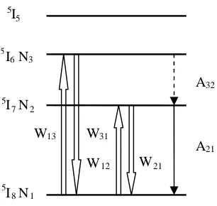
12]:-Figure 2.2:Three-level laser scheme [12].
2 21 2 21 1 12 3 31 1 13 1 N A N W N W N W N W t N (2.17) 3 32 2 21 2 21 1 12 2 N A N A N W N W t N (2.18) 3 32 3 31 1 13
3 W N W N A N
t
N
(2.19) 1 2 3
W13 W31
W12 W21 A32

![Figure 2.3: Energy level of a two-level system where the two levels comprise many sublevels [12].](https://thumb-us.123doks.com/thumbv2/123dok_us/8505899.348781/44.595.210.377.511.615/figure-energy-level-level-levels-comprise-sublevels.webp)
![Figure 2.4: Energy-level diagram for the Er3+-Yb3+ co-doped system [1].](https://thumb-us.123doks.com/thumbv2/123dok_us/8505899.348781/46.595.133.477.280.550/figure-energy-level-diagram-er-yb-doped.webp)