Int. J. Electrochem. Sci., 10 (2015) 3185 - 3191
International Journal of
ELECTROCHEMICAL
SCIENCE
www.electrochemsci.org
Note
Flexible Four-in-one Micro Sensor for Reliability and 100-hour
Durability Testing
Chi-Yuan Lee1,*, Chia-Hung Chen2, Chin-Lung Hsieh3, Kin-Fu Lin3, Shyong Lee2, Ten-Lom Chen1, Yen-Pu Huang1
1
Department of Mechanical Engineering, Yuan Ze Fuel Cell Center, Yuan Ze University, Taoyuan, Taiwan, R.O.C.
2
Department of Mechanical Engineering, National Central University, Taoyuan, Taiwan, R.O.C. 3
Institute of Nuclear Energy Research, Taoyuan, Taiwan, R.O.C. *
E-mail: [email protected]
Received: 10 January 2015 / Accepted: 3 February 2015 / Published: 24 February 2015
By using micro-electro-mechanical systems (MEMS), this work develops flexible four-in-one (temperature, voltage, current and flow) micro sensor on a flexible substrate. The flexible four-in-one micro sensor use polyimide as the protective layer, owing to its high temperature resistance. This paper will involve designing and fabricating the flexible four-in-one micro sensor. A programmable thermal shock tester and a programmable temperature and humidity tester were used to simulate the inner environment of the low temperature proton exchange membrane fuel cell. The calibration curves reveal repeatability and highly linear of the flexible four-in-one micro sensor. After calibrated and its reliability confirmed, the flexible four-in-one micro sensor will inserted into the low temperature proton exchange membrane fuel cell for local microcosmic measurement.
Keywords: MEMS; flexible four-in-one micro sensor; thermal shock testing and constant temperature and humidity testing; reliability and durability testing
1. INTRODUCTION
Due to the features of high efficiency, low pollution, rapid advancements, and low product cost, the fuel cell has been recognized as the new energy technology in the 21st century.
voltage, current and flow sensor are large, they are measured separately by the bipolar plate outside the fuel cell or inlet/outlet measurement and invasion. However, the measurement result is not the actual temperature, voltage, current and fuel distributions in the fuel cell. It is difficult to use the existing measuring method to measure the local microscopic performance change in fuel cell instantly, so that in the long-term repeated operating procedure, the fuel cell failure can only be deduced by simulation. The causes may also be discussed by using destructive analysis at a very high cost, and the result is often too macroscopic or microscopic.
Previous literatures have not applied micro temperature, voltage, current and flow sensor simultaneously to the microscopic diagnosis inside the fuel cell. This study aims to develop a flexible four-in-one micro sensor according to the product demand and technological bottleneck of low temperature proton exchange membrane fuel cell (LT-PEMFC), and embed it in the bipolar plate and inside the LT-PEMFC. The proposed sensor has four kinds of internal real-time sensing, which can enhance the added value of product and the product competitiveness.
2. THEOREM AND DESIGN 2.1 The temperature sensor
The resistance of the metal conductor will rise due to the rise of the ambient temperature. This is caused by the “temperature coefficient of resistance” (TCR) of the conductor, and it is defined as shown in Eq. (1).
0
1 d dT
(1)
where, where, α is the TCR; ρ is the resistivity; ρ0 is the resistivity when the temperature is 0°C. If the resistance temperature sensors are used in the linear range of the resistance of the conductor, it can be represented as shown in Eq. (2).
0 1 1
t
R R T (2)
The proposed micro temperature sensor uses the thermal resistance temperature detector (RTD) of the above principles [5]. Therefore, the range of temperature sensing is large and the linear degree is good.
2.2. The voltage sensor
2.3 The current sensor
The micro current sensor used in this study can measure the resistance and voltage of object simultaneously, and the current of object is obtained by Ohm's law. The micro current sensor consists of four miniature probes, including a set of resistance probe and a set of voltage probe. The voltage difference and resistance are measured by external measuring instruments, respectively.
2.4. The flow sensor
The thermal linear flow sensor’s main measuring structure is the thermal resistance heater to generate the source of heat by fixed voltage input to form the stable temperature field. In the flow field, the heater-generated temperature field will change with the strong thermal convection of the fluid. If the external heater provides a fixed amount of heat, with increasing fluid volume and heat being taken away, the resistance of heater will drop accordingly. By controlling the heat provided to the thermal line to keep the temperature difference between the thermal line and flow volume constant, the heating power should be increased with rising fluid volume. By the fixed temperature circuit design, the flow volume can be converted into electronic signal outputs [9].
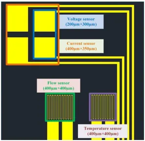
[image:3.596.150.446.450.739.2]As the thermal line flow sensor measures the flow volume by heating, the substrate material should be low in thermal conductivity to avoid the heat dissipation caused by the heat conduction of the substrate. Hence, this study selected the polymer material PI as the substrate. The schematic of four-in-one micro sensor is shown in figure 1.
[image:4.596.168.427.92.380.2]
3. FABRICATION
Figure 2. The production process of four-in-one micro sensor.
[image:4.596.186.407.426.720.2]
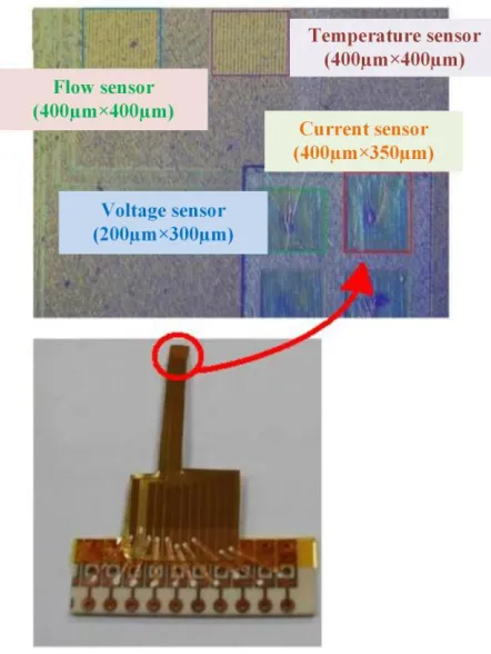
The integrated production process of flexible four-in-one micro sensor is shown in figure 2: (a) the flexible substrate stainless steel foil is cleaned; (b) the polyimide is spin coated as lower insulating layer; (c) the E-beam evaporator coats Cr as adhesion layer and Au as sensing; (d) the pattern of micro temperature, voltage, current and flow sensor is defined by photolithography process; (e) the Au etching solution and Cr etching solution are used for wet etching; (f) the polyimide is coated as protective layer, and then the voltage and current sensing area and pins are defined by photolithography process; (g) finally, the integrated production of flexible four-in-one micro sensor is completed [7]. Figure 3 shows the real product and optical micrograph of four-in-one micro sensor.
4. RELIABILITY AND 100-HOUR DURABILITY TEST OF FLEXIBLE FOUR-IN-ONE MICRO SENSOR
4.1. Calibration temperature of flexible four-in-one micro sensor
The flexible four-in-one micro sensor and the thermometer of BM-525 BRYMEN digital multimeter were put in DENG YNG DS45 Drying Oven. The temperature was stabilized at 30°C, then the electrical resistance of micro temperature sensor was captured. In the range of 30°C to 150°C, the electrical resistance was captured at intervals of 10°C, the micro temperature sensor was calibrated three times, and the average value was taken. The result showed that the micro temperature sensor has good linearity and reliability.
4.2. Calibration flow of flexible four-in-one micro sensor
The flexible four-in-one micro sensor was embedded in the fuel cell. The fuel cell testing machine 850C supplied air as the flow source. The power supply was connected to the signal pin of micro flow sensor. The anode was connected to BM-525 BRYMEN digital multimeter in series to measure the current variation. The power supply supplied constant voltage to the micro flow sensor to generate a stable heat. The reference current value at 0 l/min was measured, and the flow calibration range was 0~40 l/min. It was measured at intervals of 5 l/min. The micro flow sensor is calibrated three times and the average value is taken, the measured calibration curve.
4.3. Reliability and 100-hour durability test
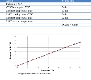
When the temperature and flow of flexible four-in-one micro sensor were calibrated, it was put in the programmable thermal shock testing machine [8]. The preset temperature range was -55°C~150°C, the temperature change rate was 95°C/min, and the temperature retention period is was 3 min. The temperature was changed 40 times, as shown in Table 1.
[image:6.596.124.480.198.512.2]
were calibrated again after the 100-hour durability test, and the calibration curves before and after the thermal shock and constant temperature and humidity tests were compared, as shown in Figures 4 and 5. The experimental result proved that the flexible four-in-one micro sensor has good reliability and durability.
Table 1. Testing schedule of thermal shock
Schedule Action Setting time
Prepare Preheating -55ºC ─
Step 1 -55ºC heating up 150ºC 2min
Step 2 Constant temperature time 13min
Step 3 150ºC cooling down -55ºC 2min
Step 4 Constant temperature time 13min
Finish 150ºC~room temperature ─
Cycle: 40 1Cycle = 30min
Figure 4. The calibration temperature curves before and after the thermal shock and constant temperature and humidity tests.
[image:6.596.156.441.568.738.2]
5. CONCLUSION
This study proposed the design and production of flexible four-in-one micro sensor. The thermal shock, constant temperature humidity tests, and 100-hour durability test were carried out for the flexible four-in-one micro sensor. The experimental result proved that its reliability and 100-hour durability are good. The flexible four-in-one micro sensor will embedded in the low temperature proton exchange membrane fuel cell for internal local microscopic measurement, to control the internal conditions of fuel cell exactly and adjust the operating parameters, so as to improve the performance and to prolong the service life of low temperature fuel cell.
ACKNOWLEDGEMENTS
This work was accomplished with much needed support and the authors would like to thank for the financial support by Ministry of Science and Technology of R.O.C. through the grant MOST 103-2622-E-155-006-CC2, 102-2221-E-155-033-MY3, 104-2623-E-155-004-ET, 103-2622-E-155-018-CC2 and 103-2622-E-155-004. The authors would also like to thank Professors Shih-Hung Chan, Shuo-Jen Lee, Ay Su, Fang-Bor Weng and Guo-Bin Jung of the Department of Mechanical Engineering, Yuan Ze University for valuable advice and assistance in the experiments. In addition, we would like to thank the YZU Fuel Cell Center and YZU common Lab for providing access to their research facilities.
References
1. C. Bao, M. Ouyang, B. Yi, Int. J. Hydrogen Energy 31 (2006), 1040-1057. 2. Y. Zong, B. Zhou, A. Sobiesiak, J. Power Sources 161 (2006), 143-159.
3. W. Vielstich, H. A. Gasteiger, A. Lamm, 2003, “Handbook of Fuel Cells: Fundamentals Technology and Applications,” John Wiley & Sons Inc.
4. H. Nishikawa, R. Kurihara, S. Sukemori, T. Sugawara, H. Kobayasi, S. Abe, T. Aoki, Y. Ogami, A. Matsunaga, J. Power Sources 155 (2006), 213-218.
5. C. Y. Lee, F. B. Weng, F. H. Liu, C. P. Chang, C. K. Cheng, Int. J. Electrochem. Sci. 8 (2013) 12580-12589.
6. C. Y. Lee, S. J. Lee, Y. M, Lo, Y. M. Liu, Int. J. Electrochem. Sci. 9 (2014) 272-281. 7. C. H. Chen, C. Y. Lee, S. Lee, Y. M. Liu, Int. J. Hydrogen Energy 39 (2014) 18337-18342.
8. C. Y. Lee, S. J. Lee, K. T. Yang, Y. M. Lee, M. S. Tang, P. C. Chen, Y. M. Chang, Int. J. Green Energy 10 (2013) 337-347.
9. C. Y. Lee, L. H. Fang, A. Su, Y. M. Liu, C. J. Lee, Renewable Energy 74 (2015) 517-522.