POLARIS.i.TIOlJ lIT ~HE G. LA.:A.""Y
um
TH.w IJI ,GE l!"_G£LLAFIC CLOUD
1: AT UIAJ112 VI'V lL4..TEAtT 1965
} .. thesis subrni tted for the De,;ree of Doctor of Philosophy
The original \Iork reported in this thesis is that of the candidate alone.
i}.";/l~~
(IT. VISV.'JT.ATI \IT)"
I
T ;BLE OF CCJTENTS
clmowledbements iv
Ch~.pter I
InJeroduction . . . . . . . . . . . . . . .. . . . . Ch~~ter II
The (101).ble channel :>ol~rilleter
1. O~tical ley- out . . . . ... . . . . 17 2. Detc..i ls of con' truction.. .. .. .. . .. . .. . .. .. .. .. 18 3. hdjustment of the optical com~on~nts ... . .. ... . 4. Depol rise::· . . . · . . . . 5. C.-,libra tor ... . . .. . . .
-u. S lertion of ffiulti:!!li ers . . . ... . . .. . 7. Electl'onic eql.J.ipment . . . . ... . .. . . .. .. . 8 . .. ountin...., the ~oL..rimete::.:' on th~ telescope . . . . .
S
.
Checkin~ the focus of the F8bry lens . . . . . ... . . 10. Tilting the pol'rime~er . . . ..
...
.
Chcpter III
Obs rvational techflique end l'eduction of data
1. Lethod of measuring the poL ris~ tion . . . . .. . . 2. Reduction of datG-. ... . ... . . ·. ·· · · 3. Elliotic8l polaris tion ... ....... ··· ··· · 4. Che ckinb the func tion of the Fabry lens ... .. . . 5. Di cu,)sion of SOUl ces of erl'or 3 'lJ1..d tl1t-ir
elinlinf'tion . . . .... . .. ... ... . . . J . Findi lC the osi tion ,-.n...;le of tnL e 11..1.8 ~orial
north- south \i th respect to position' 11. le sc le ensraved in the pol'rimeter . . ... .. .. ... .
21 24
29
31 33 35 36 373b
.1.~ , ) 45 4546
I
f,:
ii
(continued) TABLE OF COlTTENTS P. GE
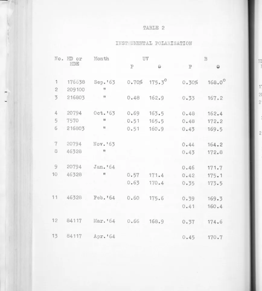
Chapter IV Instrumental pol arisation
1. Definition . . . 54 2. Polari sation inherent to mirror •...•...• 55
3
.
The evaluation of t e mirror polarisation .••.. 57 4. Observational data for unpolarised stars •....• 585. Errors... 59
6. .1ean instrumental polari sation... 61 Chapter V
Observational data for wavelength dependence of polarisation
1. Selection of stars .•...•...••. 63 2. Selection of fil ters ..•... 63
3
.
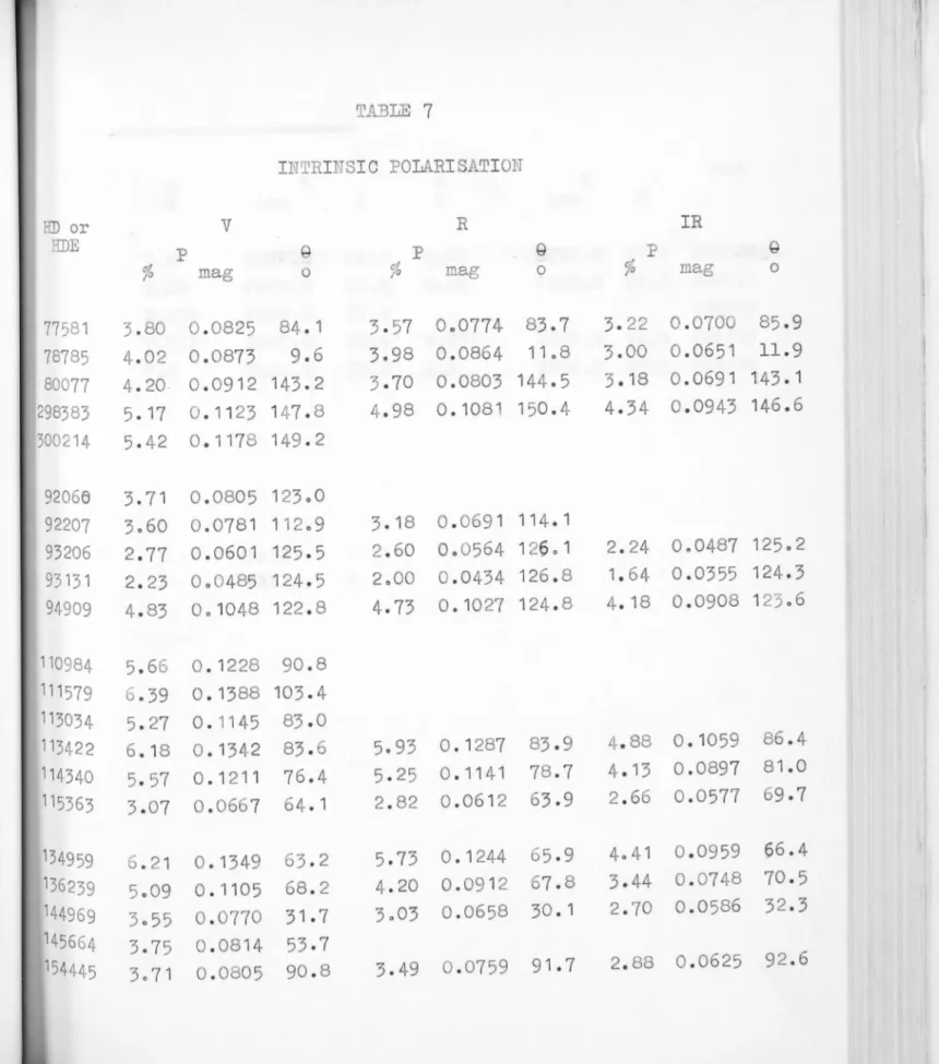
Stability of the instnunent vrith filters ...• .. 66 4. Observations of polari sation ot U,B,V,R'lild IR i'or programme stars. . . 68 5. Intrinsic polarisation ... ... ... ... 70 6. Discussion of errors (internal) •... .... .... 70 7. Duplicate observations plot . . . 75 8. Calculetion of external errors ... . ··· 75 9. Comparison of OUI errors \ii th those of other
obse:r"'Vers. . . . . . . . . . . . • . . . ... . ... . . . . . .. . 78 10. Photometric [m,d spectral data for :,rocraLllIle
stars.... . ... . .... . . . . . . . .. .. . . . . 78 Chapter VI
Uavelength dependence of polarisation in southern Milky ay ,
1. Observations by other observers ..•... • 81 2. Theoretical results for the wavelength
i i i
(continued) TABLE OF CONTElTT
3. Our observations of v/avelength dependence
of polarisation. . . 87 4. Polarisation and extinction by c...ust particles 88 5. :Tormalisation of P
t . . . .. . . .. 89 6. Alignment parame t er. . . . . . . . . . . 93
7
.
Correlation between P/
A
and the \lavelenothde}endence of pol~risXti~n... 99 8. Colour-orientation dependence .. . . .... .. . ... 102 9. Correlation vIi th colour exces.J.. . . 104 10. Interpl'etation of our results.. .. . . . .. . ... 105 11. Conclusion.. ... . . .... .. . . .. . 107
Chapter VII
Interstellzr polarisati on in the Large Eagellanic Cloud
1. Previous observations . . . .. . . .... 111 2. Sin,;l e- channel observe:.. tions. . . . . . . . . . . . . 112
3
.
Double-chamlel observations .. .. . ... .... . . 114 4. ; avelength de}endence of polarisation .... . ..• 116 5. Discussion ... . .. . .. .. . . ... . ... ··· · ····• 117 6. Conclusion .... . . . .. .... ... . .. ... . . · · · ·· 124Chapter III Pol~risation in Eta Carinae
4-iv
~ CnTO~7LEDGEI1El TS
I am greatly indebted to Professor B.J. Bok for his const[nt hel and encoure.gemcmt in the
course of this study and to Professor S.C.B. Gascoi.;ne ~ho has ~iven so freely of his tine not only in the desi~n and construction of the double channel
:901arimeter but also in advice and guidance throughout the investication.
Dr. T. Walraven acted as adviser durin~ 1963-64. Dr. T. "Jalr::ven has always been more than tSenerous in advisin . me in the pro bl ens connected Vii th the making the depol' l~ser, adjustment of the optical components in the polarimeter and electronic probl ems. I am
deeply indebted to him for the unfailing support,
he Gave, durinG this period.
I 'Iould like to express my sincere thanks to
Drs. A.'N. Rodgers, B. Westerlund and L. Searle for the Dl..lmelOUS discussions I had \ i th them.
I am thankf'ul to r.Trs. P. Kennedy for the cl"ssification of the sgectrograLlS.
I Gra.tefully acknowledge The Australian National
University Scho18Tship Hhich made possible my
CI PTER I
IlP.J:RODUC TIOn
In 1946 Chand~asekh r showed from 2. theoretical
invcstic;ation thc.t early B st2.rs should display as
much as 11.7% linear polc:...risation at the limbs of
their discs because of Thompson sC2.tterin~ of free
electrons in their atmospheres. Bina~J stars \nth primaries of early type snd secondaries of late type
\"fere found to be the best c2.ndid2tes for testing this theory, and the ... "'olarisation \fas predicted to appear
only immediately before and 2fter eclipses. But
photoelectric observ tions by Hall (1949) end by
Filtner (1949 a,b) of the binary system C Ce~hei showed that the light from C Cephei is polarised
5%
,
which value rem8.ined unchanged at different phasesof the eclipse.
Subsecuently, Hall and Hiltner observec other
eclipsing systems as well as single stars and found that
the light from many sinsle stars is elso linearly
pol~rised . This led to the discovery that the polarisation they observed is not of stellar orisin but of interstellar
-2
-Hiltner (1951,1954,1956) 2nd Hall (1958) extended
their observations ino.ependently to more than 4000 stars,
distributed all along the northern ~Iilky aYe Most of these are early type stars having distances 100C to
3000 narsecs. The equipment used by Hiltner ,as a
d.c single-channel polarimeter using polaroid filter
as analyser. Hall usect 811. a. c. t echnique with a
rotatabl e plane parallel calcite plate as analyser.
In the Southern hemisphere E.V.P. Smith (1956) observed
200 st ars for polarisation.
The above surveys aJ.1.d the observations of others
(T-Iall and Serkovrski 1963) have shown the following:
1.i The polarisation is independent of spectral type;
ii. The l~rgest amount of polarisation is observed
nearer the plane of the gal~xy and the polc.risation decreases rapidly with increasing g~18ctic
1 ".ti tude;
iii. For a star's li~ht to be ~olarised, it is a necessary but not ~lfficient condition that
it should have undergone interstell ar absorption.
The polarisation is correlated "/i th colour excess
in such a way that the ratio p/~-V does not
exceed the value 0.195 (Hiltner 1956, Scbmidt 1958).
-3
-of the electric vector shows a striking tendency to
lie parallel to the plane over a long range of galactic
longitude. On the other hand, there are regions where
the electric vectors are randomly oriented and where
the amounts of polari sation are smaller.
The above observational evidence has ~de it clear that the pol~risation observed in the continuum of the stars' radiation is of interstellar origin. Its
correlation with colour excess shows that both interstellar
polarisation and absorption are complementary manifestations
of the interstellar particles.
An attempt made by Thiessen (1961) to interpret
the polarisation as caused by synchrotron radiation
in stellar atmosphere has been shown by Behr (1961) to be
based on a faulty selection of data.
To explain the interstellar pol''''risation by
interstellar grains, it i s essential that the grains
should be elongated which implies that a large scale
mechanism must be present which orients these grains
in space. For quantitative treatment, extinction
cross sections for particles shaped as long cylinders
have been calculated for both dielectric and etallic
particles (Van de Hulst 1950, 1957), (Smith <.lIld
-4
-laboratory extinction cross sections for oblate s Jheroids
have been obtained by Gr eenberg (1960,1963), and the
results show that the polcrisation measurements obtained
for completely orient ed prolate and oblate spheroids
are nearly the same as those for completely oriented
infinite cylinders obtained by theoretical calcul&tions.
Platt (1956, 1960) has suguested that the lLrge
unsaturated molecules of sizes of the order of 20
muy 0roduce l ol~risation because these are likely
o
to be elongated since the electric charges tend to be
at the ends of the long axis of the particles. These
molecules are varamagnetic.
The suggestion that interutellar polari sation may
be causeC by the graphite flakes, which are supposed
to condense at the surfaces of the cool N stars and
to be ejected into the interstellar medium by radiation
pressure, has been put forward (Hoyle and' ickramDsinghe
1962) . Once the graphite flill~es reach interstellar space, they will be easily covered by a thin manti e
of ice, (' ickramasinghe 1963, 1965). For gra~hite,
the conductivity perpendiculo.r to the basal plane i s
about 100 times l ess than that po.rallel to the basal
-5-Of the ali0nment forces proposed, the Davis
Greenstein mechanism (1951) is the one most generally accepted and is 2.lso one vlhich explains the observations closely. This mechanism aSSlrnes a magnetic field
p~rallel to the plane of the Galaxy. Davis and
Greenstein suggested that the field i s nearly uniform along a spiral arm. Chandrasekhar and Fermi (1953) had deduced from independent considerations, that the equilibrium of the gas in the spiral arms of the
galaxy, requires a magnetic field of the order of 10-
5
gauss to be embedded in the s)iral arm along its axis.According to Davis and Greenstein, the elongated interstellar dust particles, assumed to be paramagnetic, are in a state of rapid rotation, of the order of a million radicffis per second, resulting from collisions with interstellar gas atoms. In a ID.-:.gnetic field, part of the rotational energy is dissipated by
pararn~.gnetic absorption in such a way as to align the short axi s \fi th the direction of the mcgnetic field. As the field i tself i s generally p2rallel to the
gaL.-.ctic plone, the p:::.rticles \lill be aligned lith their short axes parallel to the galLctic plane. When \Ie
-6
-line of sight. This direction, "Thich is the di rection
of the electric vector, indicates the direction of
the projection of the magnetic field on the plane of the sky.
:fuen the line of sight is perpendicular to the
ma0netic field, i .e. perpendicular to the axis of
the spiral arm, one can see much alignment and hence high polarisation because the particles al'e in rapid
rotation around the short axis. When the line of
sight is p; rallel to the magnetic field i .e. along the spiral arm, one sees little alignment and less
pol arisation. The si tua tion vlill be between these tvlO extremes when the line of sight makes an an.:;le
with the magnetic lines of force. This model explains
the longituoinal variation of the observed polarisation
in our Gal axy, but it appears likely that important
systematic deviations from this general picture
exist (Hall 1958) . The mean direction of the magnetic
field derived from polarisation data is in good
agreement with the direction of the spiral arm delineated
from O,B stars Llld other Population I objects both in
the northern and southern hemispheres. Behr (1959)
observed 250 stars, most of them nearer the sun than
250 p .rsecs and his observations suggest that the
-7-In their survey of linear pol risetion of u'-'.l'lctic
radio emission G.t ~·08 11c , I~athe;;son and t ilne (1965)
found thc.t the pol ris eel re .... iol1s ~:re confined to 2..
lide band \lhich is ')er end~ icul l' to our 0 ' alcctic
plane. They also found that the direction of the
elec~ric vectors of intrinsic polar~sation is pe~pendicular
to the gal2.cti c plane. _"l.ccol'clinS to t:le s~"nchrotron
theory, this direction is perpenclicul" to the maenetic
field. As the distance to the re ... ions '.There ~he radio
emission ori -inates is about 250 ::>0.1'8 cs, -'.;he gredicted
direction of the ma....,netic field in the vicinity of the
sun, is frOIa 2300 and 50u , which e;rees r 11 vi th
Behr 's results.
The :D~vis-Greenstein rlech' 1i r::J. C2.n be applied to
al l ty:!)es of t>rains. A stron~ rna 'netic field of the
order of 3 x 10⁻⁵C~u::::s i s rec·uired for ali..;nine the parema 'netic dielectric )a1'ticle . ~he ..;netic field
reQuired vro'\.1.1d be less or I e:!.'ri tes , iron l'!'1ins , GraI:L1i te
f'l "ke J cU1d In. tt p< rticl es (~Tall and Serkowski 1963,
ickramasin..;he 1963).
The theoretical maximum value of the ratio
1
-8
-prol te spheroids obtained from micro 'rave measurements is 0.09 (Greenberg et al 1963) for a refractive
index 1.33 - 0.05i (dirty ice) Ylhile for gra hite, metallic, ferrite and Platt particles the maximum
PIAv
i s very much larger; these values should becompared to the observed maximum of 00065. ( v is
assumed to be equal to 3 x EB_V)'
Thus in the case of dielectric ice particles alone,
the difference betVleen the theoretical ms.ximum value of
PIAv
and the observed msximum is small indicatingthat, if the ice particl es vrere considered as
interstellar crains, they should be nearly com91etely aligned. This rigorous condition does not arise for
other types of p rticl eso
The first observations of wavelength de endence
of polaris8tion by Hall and Hiltner had shorm th3t the
polarisation is nearly constr.nt with wavelength from
ul traviolet to visual becominG smaller towards the
red, Yli th a st eady decrease towards loncer wavelen[, thso
Subse~uent observations by Behr, Treanor, and Gehrels
have shown that the v.,ravelength dependence of polarisation
also decreases towards the ultraviolet and that
there are cha.nc;es in wavelensth dependence of po12.risation
-9-wavelength dependence of pol arisation for perfectly
orientec infinite cylinders of refractive index
1.3
for the Oort-Van de Hulst size distribution, have been made and the computed wavelength dependence curve agrees well lith the ob serve ~ one.
Davis (1959) has given a qualitative interpretation
of Behr's wavelength dependence of polari sation
observations in terms of differences of grain alignment. He also pointed out that any chan~e in the size of
the particles or the refractive index of the particle will shift the wavelength at 'Thich the maximUL1
polarisation occurs. Of course a knowledGe of the
alignment force is essential for the study of these chanGes. Thus, in principle, the study of wavel ength
dependence of polarisation is a method of determining whether or not the dust grains varJ from region to region in size or chemical properties.
Scope~f the present investigation
1. avelenGth deQendence of polarisation in the Southern
Jllilky '!N..: One of the problems v~e have undertaken is
the study of the Havelength dependence of po12risation for stars in different regions of the Southern IIilky .ay.
A double channel polarimeter was constructed at
-10
-fainter stars could be studied without loss of accuracy,
-llie sgectrum from ultraviolet to infrared was divided
into 5 broad bands by filters (U,B,V,R,IR).
26 stars were chosen for observation from those
observed by E.V.P. Smith (1955) in her "Survey of interstellar polarisation for the Southern Milky 7lay".
These have been selected in such a way that they are distributed from Vela-Puppis to Sagittarius.
Throughout most of the galactic plane, the dust clouds near the sun produce much of the observed
polarisation. In the southern hemisphere, the
Vela-Puppis nebulpe, Coal Seck and Ophiuchus complex come under this category. In Vela-Puppis the observed polarisation may be due to the dust associated with H II regions and overlying dark nebulae (Whiteoak 1962).
Nevertheless, in certain directions more remote clouds
contribute to the effect, such as the Carina region,
and also there are cases where we are not able to fix the position of the clouds, such as in the direction of
the galactic centre. Further, according to current ideas on spiral structure, the clouds in Vela-Puppis,
the Coal Sack and in Carina lie in our own spiral arm
-11
-selected, may be located ei ther in our own spiral arm, or in the inner part of the Sagittarius arm. Thus, by detailed studies of our selected stars, we may hope to investigate the differences in optical properties and the alignment forces , if any, of the medium over
different regions of the southern l,'iilky ay.
2. Interstellar polarisation in the Large ~.~agellanic
Cloud: Polarisation observations in our Galaxy can be
made only to distances of a fevl kiloparsecsj further,
beyond a certain distance their interpretation becomes ambiguous because of the presence, in the line of
sight, of several clouds of dust having alignments
in different directions. Thus, observations in our
Galaxy reveal the direction of magnetic field only to a limited distance. Therefore it i s im:;>ortant to
observe external galaxies to understand the behaviour
of the lUc.gnetic fi elds on a Galoctic scale.
The problems connectec. \lith the measurement of
)ol arisation in external galaxies are:
i . If we wish to have a reasonable eX.gectation of high 1!ol r.risation which can be me8sured with high percentcge
accuracy then we should select galaxies ri ch in cosmic
dust. The best candidates for such observations will
-
12-~as and dust on which magnetic fields can act (I.:Leinel 1953) . ii. To make polarisation measurements as in our orm
Galaxy we should be abl e to measure individual stars.
All external ualaxies except the I,Iagellanic Clouds
are so f~r away that it is impossible to isolate
individ~ml stars vath existing telesco~es. The next
best method is to use bi.:; focal plane diaphrag'ms
and t len measure t_le integrated effect of all stars
contained in the c1iaphro.gm. Here we run into the
problem that \Ie receive not on1 stellar radiation,
port of which has been extin:,uL.hed by the dust ~ articles, but 21so radiation from the nucleus of the salaxy
vihich has been scattered into the beaJU b:r the dust
particles. The intensity of the latter component
varies accordinc to the part of the ~a13xy selected
by the diaphraGm. Such measurements have been nBue
by Ohman (194·2) end A. Elvius (1951,1956). The
interpretation of the observations i s further complicated
since the radiation scattered from the bri[,ht nucleus is Dolarised neroendicular to the direction of the
"- ~
-~oll.riso.tion arisinG fro~ the absorpti on of the
articles.
iii. The aSJect from v/hich polorisation can best be
-13-perpendicular to the equatorial plc,ne of the ,-,alaxy.
The \/hole of the gelactic plane, in which the mac-net'-' ic
fj. eld is contained, if:; then perpendicular to the line
of sid~t and maximum alignment and polarisation can be
ex]ectedo
The ealaxy r131 'lualifies ·r.i..th regard to points
one and three but its distance is so Great that
individual stars cannot readily be observed. As a
ne rest approximation, Hiltner (1958) observed 21
.::;lobul -.r clusters brighter than 17th masni tude "lith
.. he 82-inch l:cDonald telescope 'r.i.. th the aid of a
photoelectric single-channel ~olarimeter. The
results sho\l that the electric vectors have a
tendency to be preferentially aligned in a direction
parallel to the m&jor axis of 131 . The maxim~un
polarisation found is 0.061 mag and the average ratio
of polarisation to absorption is 0.030 . Until now,
no individual star has been observed for polarisation
in any external ~alaxyo
The Large MaGellanic Cloud is at a distance of
les8 than 1/10th of the distance of M31 and provides
an unparalleled opportunity for examinine the
distribution of the maGnetic field in an external galaxy
-
14
-Even though the Larue rIagellanic Cloud is classified as an irregular galaxy, observations ShOT that it is a highly flattened rotating system and t!lere is evidence
that i t is a barred spiral with, perhaps, faint outer spiral strLlcture (de Vaucouleurs
1955)
.
The line ofsic;ht makes Em angle between
75
0 and63
0 \lith the planeof the Cloud according to de Vaucouleurs
(
1
955), 45
0according to Westerlund
(1963)
End55
0 according toHindman et 0.1
(19
63
)
.
But the dust content which isessential for the observation of polarisation is
-)robably much lm:er in the L2_rce Eagel lanic Cloud
(T. 7alrdven ~ J.H. 7alraven
1
96
3,
Feast et al19
60
than in the Gal C".xy.
Polarisation observations VTere lTI.2.de for
30
reasonably certain stcl lc:-.r members of the Large LIabel lcmic Cloud.3. Polarisation in Et2. Carinae in U,B,V,R,end IR: The
object Eta Co.rinLe is situated inside the dominatin~
Eta Carinae nebulae. Large 2JIlOunt of ;:012risation was discovered by Thackeray
(19
56
)
in the halo around thenucleus of Eta Carinae and the same was confirmed later
by 'fes elink
(1962).
~his special nat-ure of thepoL.risation in Eta Carinae has pro.lJ)ted us to include
Eta Carinae in our ~)rogram:1I1e of vravelength de)cndence
CHltIJTER II
T}IE DOUBLE Cill lTl!EL POLA.RII':ETER
~'raximum polarisation observed in stellar radiation
is
10%
(Hiltner1956)
rnd more often polarisation is onlya fevi percent. Thus the polarisation measures involve
measurements of .small differences of intensity and
differences of the order of hundredth of a percent
become important in the study of wavelength dependence
of polarisation.
The methods used to measure polerisation h've
recently been adequately SUIilll'laris eO. b:r Hall and Serkowski
(1963)
and Hiltner(1962)
.
The chief sources of error inpolorimetry are photon or shot noise, scintillation
noise, variations in atmos0heric transparency and the
polarisation of the telescope l'lirrors. The first
is inherent in the si.r-.;nal and the second and the third
can be l[.rgely eliminated by sui table design as in
either the A.C or the double channel D.C polarimeter. The polarisation produced by the telesco)e mirrors
constitutes an insiduous dource of error and it can
be eliminated only by rotating the whole telescope,
-1.6-Polarisation measures are absolute in character unlike magnitude and multicolour observations which are
expressed to a group of standard stars. Thus the instrumental characteristic can be carried from one
observation to another in photometry while in polarimetry, it is necessary to remove all instrumental characteristics
because of its absoluteness both in the amount of polarisation and the position angle. To achieve the above requirements, the need for care in the design and construction of the polarimeter cannot be
overemphasized.
The D.C double channel polarimeter gives a
somewhat better signal to noise ratio and since there was a good deal of experience in this observatory in the measurement of small direct currents and since most of the electronic components needed were already
available, it was decided to construct a double channel polarimeter on the same lines as Hiltner's (1962)
and Behr' s (1956).
Prof. Gascoigne designed the polarimeter and it was constructed in the Observatory workshop. A
calcite Wollaston pri sm was purchased for the analyser from the Karl Lambrecht Company. The prism is 24 rom
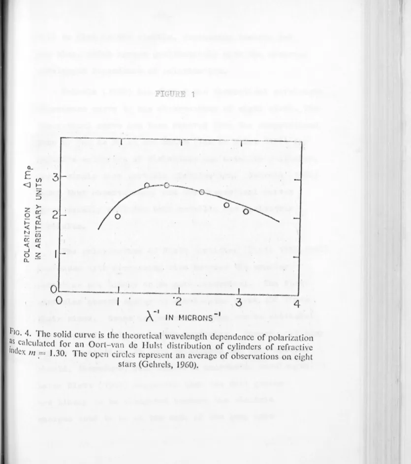
FIGURE 1
THE
SCI-!E~,
TIC DIAGR. : OF THE DOUBLE m:.:.l1:.TEL POL!-~
I
Ld~ER
--
_f/IB BEAMQUARTER YlAVE
APERTURE - ___ _
--==-+-"7 APERTURE VI EYlER
I I ",.----fA BRY LENS
WOLLASTON
P"SM_~
\
CHHODE
~D-+---1~
lJ
~
ij
0
i111 \ 1 M, \
r
I
MIRRORS LENS FILTER CATHODE L
-1
FI L TER LENS
r
-17-and the end-on faces are perpendicular to the geometrical
axis of the prism. The deviation of the ordinary ray
from the central axis of the crystal changes with
wavelength from 110 to 80 from ultraviolet to infrared.
For the extraordinary ray, the change is from 100 to
o
7.8 • The reflection loss inside the ~ollaston, for
the ordinary ray is 0.003% , and for the extraordinary
ray is 0.8% •
1. Optical lay-out: Figure 1 represents the schematic
optical lay-out of the polarimeter used at the Cassegrain focus of the 50-inch telescope. The Fi re is drawn for a focal ratio of 18:1 .
i. provision for A /4 plate which c~n be brought into
the beam at any time.
ii. Provision for mounting a depolariser which cru~ be
brought into the beam whenever ~anted.
iii. Aperture rvheel having apertures of different sizes.
iv. A prism which deflects the star field into an
eye-piece. The prism can be removed from the beam
during exposure.
v. The first Fabry lens - focal length is 41.6-inches
vi. The calcite ollaston prism
vii. The ordinary and extraordinary rays are reflected
perpendicular to the geometrical axis of the crystal
FIGURE 2
MIRROR-CONDENSING~LE~iSi1IT-~.u..- ~
rJ4:
l
caoeox
I"t.OM1NG FACE/.~ I
Il..OO< '
----
--,
I
I
r II
~IRROR
ONDENSING LENS
WHEEL
BEARING
~COLDBOX
L 1 I, MOUNTING FACE"
WOlLASTON II ' "":
~
!
~
!
!n~
,
I
CALCITE WOLLASTONMOJNT2rNG
I
'
r
rn
___
~_
lr
r!
~
-
2:
I
'
~:~~t!NeIEWER
II.OCK ___ I r-'l I 1 . 1 ' I _ I _APERTURE WHEELm
'
, ,
OEPOLARISER- I . ' BEARING
"/4 PLATE
-
18-viii. The condensing lens which forms an image of the primary mirror in the cathode: focal length
=
5.9-inches (One for each channel)ix. Filter wheel (One for each channel) x. Cold box (one for each channel)
2. p-~tails of construction: A primary requirement is that the entire optical train should be accurately rotatable about the geometrical axis of the crystal. The axis of the polarimeter must therefore be made to coincide as accurately as possible with the axis of the prism. Since only a small relative movement of one of the optical components may introduce a
considerable error into the measurement, the rigidity of the whole system is of first importance.
The instrument was based on an aluminium block 1, 6.37 inches diameter and 3.9 inches thick (Fi re 2). It was turned on a precision lathe and a hol e of
1.25 inches diameter was bored in the centre of the block for mounting the 1ollaston prism. The two bearings were also turned at the same time. This
block rotates inside a steel tube of diameter 7.62 inches, length 5.87 inches and wall thickness 0.25 inches.
-19-To the front end of block 1 , another aluminium block 2 , diameter 6.60 inches and thickness 1.93 inches
has been _attached. It houses two brass wheels of
diamter 3.6 inches having holes of 1.125 inches
diameter. It also houses the aperture wheel of
0.125 inches thickness and diamter 3.6 inches. The turning controls of all three wheels have been brought to the back of the polarimeter. All three wheels are
eccentrically fixed.
To the back of block 1 an aluminium block 3 of
4.87 inches thickness in barrel shape (8.5 inches long and diamter 8 inches) has been attached. This
houses the two mirrors (cut at the angle 400 50')
which deflect the ordinary and extraordinary rays to the condensing lenses. After the condensing lens
a filter wheel is mounted, which can take seven
one-inch filters. At each end of the block, a five inches square plate is attached with a hinged plate
which can take the cold boxes. As a whole, the
polarimeter weighs 60 lbs. without the aol d boxes.
2.1 ~perture wheel: This wheel consists of six holes of diameter 6.4 , 4.0 , 2.5 , 1.6 , 1.0 and 0.3 rom
which correspond to 57 , 36 , 22 , 13 , 9 , 3 seconds
-20-Each hole can be brought into the exact centre of the block. Special precautions have been taken to see no error occurs in the centring of the apertures.
To avoid any spurious polarisation due to scattering,
the diaphragms are tapered behind the apertures.
2.2 Wollaston ~rism: The ~ollaston prism and the first Fabry lens (a plano convex lens of 41.6 inches
focal l ength and 1 inch aperture) are put together
inside a brass tube and screwed in, at one end to
form one unit. The inner diameter of the tube is
such that it will hold the prism vdth no movement. The outer diameter of the tube fits exactly inside
the central hole made for the ollaston prism in the
aluminium block 1 •
2.3 Mirrors M1 and M2: Mirrors ] 1 and H2 are plane
mirrors ground at our optical workshop. The surfaces
are aluminised. They are mounted in small brass blocks and introduced into position from the back of the polarimeter. Provision for tilting these mirrors, for pushing them in and out and for rotating
them have been provided by eccentric and push-pull
screws.
2.4 Condensing lenses: The condensing lenses are of
-21-(ouble conve:: lens
'it'l r ... C.L't11.;.'8 C.u7 inche8. T:lis co:.werucs th ben 1
to t'lE: cat~loc1e [.l1.C~ bas been )laced. 2."~ 8. dist~.ncc
0::.' ( . ,-,3 inch8 S fro "lJ'18 j.rst F .by] lens. This lens
con1)inecJ. Hi th tl.8 .oL.'st F 'or./ lens forms an e _ui vL1ent
f'v' teIll of' foc 1 1en ... th 6.1 inc cs. '.;he i"'12.Ge of -'-;l-:.e
o jcctiV8 i::. fo_'mea c.t a dis'~cnce of 5. 1 incher>, ,-:my
::1'0111 the condcnsin~ lens. The size of the iTIl2.C e of th~ 50-inch mirror on the cathode is 8.5 IJIll •
3. : djus,,:,c!I!e}~t. _o_f _ t.he. _0. )ti.c_B:..~ c.o.r~one.~t..'~: To djust the
no-:i t ion of t 1e ',011 r ston 'Jrism, the fo110 rin~ 2.rr&1:.:e cent
\1 S set 1.111 in the labor tory:
Li ,ht from a cource i -renderer. 9201'£'.11e1 ~)Y .ue~ 1S of
~ lens. The 01 rimeter is mounted rouch t 1 t i t s
'_.0"" face is per~)endicu1:.. r to the )ara11el be .Tr in
"1 fo1lO'.rin..; manner: plane Hir~o1' is fL~ed 'x:1'<..11el
.~() 'h~ _ront face of the polr l'i!"letel' and the t i l +
0''> t 1e f)' mt face is ~ djus ted <'0 tha.t tll rl f1 "'ctec
H, ht from the Ill' ne l.1irror forLls ~n imace in the
30urce itself. ~:he 01 l'iraetei' front f.J.ce is then
pel'pendi cu1 l ' to . h ral:e1 becun an the )l8one "irror
i r moved \;-1. thout disturbinG the pol\.. rill ter. The
1011'~ston l.:mi t io int'L'oduce 1 in its .,lace in block 1
,:.no. rotated until orc1in~ ry and c:rtraordinary i q~es
- 22
-mirrors I.11 ' M2 are introduced. At this position,
the . ollaston unit is permenantly screwed into the
aluminium block.
3.1 fo.djust~ent o_i_the mirro~(l11 an4. M2): The
polarimeter was fixed on a sturdy t~ble, on four metnllic blocks, such that the rotntion axis is
perpendicular to the surface of the table. The
aperture of the polarimeter was illuminated by a
distant point source of light. The mirrors 1:11 '
end the two condensing l enses are 91aced in position.
The tilt of 1111 and 12 is adjusted to get the light from 'lo11aston prism roughly in the centre of the hole of
the cold box face. A tub e with an eyepiece at one end, is fixed to the centr21 hole of the cold box fqce, throu[':h which the ordinary and extraordinary rays emer,("e from the polarimeter. The focus of the evep1ece i s kept 1n the position of the cathode. The Fabry lens tor'ether wit the condensin,3 lens of the polarimeter form an imafe of the liGht source
in the eyepiece. The polarimeter is then rotated while
observing how the image moves in the eyepiece. The position of the source and the tilt of the prism which
directs the lir'ht into the polarimeter are adjust ed until the image ceases to shift in the eyepiece "Then
-23-the beam entering -23-the polarimeter is made to coincide
with the rotation axis of the polarimeter.
The image of the source can be brought to the
centre of the crosswires in the eyepiece for each
channel by adjusting the tilt and position of the
mirrors M1 or M2 •
It is also essential to see that the ray which
emerges from the polarimeter and passes to the cold box
is perpendicular to the rotation axis, so that the
light falls on the cathode perpendicularly. In order
to check this, the eyepiece tube is removed from the
central hole of the cold box face, and a plane mirror
is stuck to the hole such that its surface is parallel
to the cold box face. If the image of the source can
be seen through the hole at the same time as the
observer's eye can be seen in the plane mirror, then
the light ray is perpendicular to the cold box face.
The mirrors M1 and M2 are adjusted until this condition
is satisfied. The above adjustments were done with a
visual filter.
3.2 Mounting the quarter-wave plate for the measurement
o!.~llip.tical polarisation: A
1\
/4 mica sheet, forvisual light is mounted in the first wheel of the
-24-inserting it in between the crossed polaroids whose axes are known. When the mica is brought into the beam, the fast axis makes an angle of 450 with the
principal plane of the Wollaston prism. This is checked
experimentally in the following Vlay:
In the laboratory, the aperture of the polarimeter is illuminated by a fully polarised beam. The polarimeter
i s rotated until no light comes through one of the channels, say channel 1 • The mica sheet is brought
into the beam in front of the aperture of the
pol arimeter. If the angle between the fast axis of the mica and the principal plane is not 450 , the light
can be seen coming through channel 1. In this case the mica i s rotated until again no light comes through
channel 1 • The angl e between the fast axis of the
i\
/4 plate and the principal plane of the lollastonprism is t hen 450 •
4. Depolariser: The readings taken with the depolariser
in the beam indicat e the zero level from which the measurements of polarisation are made. Hence, it is
-25
-Billings (1951) analysed the Lyot type depolarisers
mathematically and showed that the efficient depolariser
should consist of 2 x-cut quartz or calcite plates
(optic axis parallel to the surface) having thicknesses
in the r tio 1:2 . These two plates should be put
together so that the fast axes of the two pl otes make
an angle of 450 •
The depolarisation failure dp because of the error
in the ratio of the thicknesses,
dp
=
p
=
dx
=
x
=
dp
=
p2-
3 dx x depolarisation failureamount of polarisation measured
error in the thickness of the thick plate thickness of the thinner pl ate.
The alignment of the fast axes is also important.
A small error (. in this alignment leads to a depolarisation
failure
dp
=
lL::..-
sin 2 E: )_ )P(1 -
T1
+ sin2()It is important to note that the depolarisation failure
is a function of the amount of polarisation measured.
Natural light is unpolarised because the direction
of polcrisation and the amplitude vary erratically
and rapidly with time, and in any sufficient interval
-26
-light of broad band of wavelength is passed through
a Lyot type depol .riser, the light of different wavelengths
undergoes dofferent amount of retardation and the light
emerging has all possible directions of polari sation.
Thus it i s important to bear in mind that the natural light i s depolarised because of integration over an
interval of time while in the depolariser the depolarisation
takes pl ace because of integration over a range of
wavel ene ths •
£' 2(n - n )t
u~ __ e 0
{ \ -
/\
0-
A
=
angular retardationn ,n
=
refractive indices for ordinary and extraordinarye 0 rays
t = thickness
The greater the retardation introduced, the greater
the possibility of depolarisation. The retardati on is proportional to the thickness of the pl ate for a
particular wavelength and particular material. A
calcite plate gives ten times the retardation of a quartz pl ate of the same thickness. The range of wavel engths analysed should be sufficiently brocd.
If two quartz plates having thicknesses of 1 rom and
2 Iron are combined to form a depolariser and light of
o
band width of 100 A is passed through, the failure
-27-Making a depolariser in the observatory optical shop:
The quart z crystals were polished and those having no
air bubbles inside and with no colour were selected.
An optical arrangement consisting of a light source followed by two crossed polaroids was set up on a
horizontal pl ane. One of the polaroids pl ane of
vibration was fixed in such a way as to be perpendicular
to the hori zontal plane. The crystals were placed
one after another in between the crossed polaroids and
the position of the opt ic axis was determined. The
surfaces were ground so as to become parallel to the
optic axis. This was achieved by grinding the surfaces
little by little and t esting the crystal s in the above
arrangement until a uniform illumination was obtained
vlhel1 the crystal was placed lengthwise with respect
to the line of propagation of light. At the same time
the thicknesses were also reduced to
5
mID for one quartz plat e and 10 mID for another quartz plate.4.2 To make the angl e between the optic axes of these
two plates 450 : The pl tes were kept in between the
crossed polaroids so that the surfaces were perpendicular
to the line of propagation of light. One of the sides
was then ground to make it parallel to the optic aXis>,
as in the previous method. The other side of the plate
-28-side as one. The optic axis was parallel to the length
of this plate. (length of the pl ate
=
20 mm : breadth isequal to 14 mm.)
The second pl ate was kept in between the crossed
polaroids in exactly the same way as the first one,
but this time, one of the sides was ground in such a
way that it makes 450 with optic axis. Then the other sides of the block are ground to make a rectangular
plate n th thi s as one side.
Now these two rectangular plates are placed one
over the other with a strip of thin paper along the
edge of one of the plates, coming in between them.
They can be aligned so that all sides are parallel to
each other and taped all around so that they will not
move separately between one another. This constitutes
the depolariser.
4
.
3
Testing the thickness ratio: The plates of 5 mmand 10 mm are first checked by a micrometer to an
accuracy of 0.02 mm . To check the ratio of the
thicknesses 1:2 the following experimental arrangement
has been set up: A light source followed by two crossed
polaroids, followed by a prism spectroscope, is arranged
on an optical bench. The
5
mm and 10 mm plat es are-29
-the fast axes make an angle of 450 \uth the plane of vibration of the polaroid and the location of one of the fringes is noted by means of cross hairs in the
e~,repiece of the spectrograph. From the number of fringes seen in aparticular wavelength interval,
thickness x of the plate can be calcul~ted.
AI
,,~ 1=
,\
1-1\,.,
,
-2-( n-~---n ) .~ e 0 xx
=
thickness of the platen
=
refractive index for ordinary ray one
=
refractive index for the extraordinary rayA
l
A~= favelengths of two adjacent fringesThe thicker the plate the more crowded are the fringes. If the plate thicknesses are exactly 1:2 ,
at a narrow portion of the spectrum, the 10 mm plate
should show exactly double the number of fringes as seen with the 5 rom plates.
5. Calibrator: The polarimeter is attached to the Johnson photometer off-set guiding box. To check the stability of the polarimeter's performance from time to time, provision to inject a known amount of
polarisation by a tilted glass plate has been provided.
As it i s necessary to keep the tilt of the glass plate with respect to light beam constant, two glass plat es
"'--~2
---\
\
\
\
\
\
\
QUARTZ
\
PLA"- ES \
I
/"ll-I
/ FIGUP.E 3
C
AL
C
I
E
PRISM
-30-clear that a
1 + a2
=
a , which can be made to remain constant by attaching the two glass plates to a unitwhich is shaped as in the Figure. The advantage of
this system is that minor changes occurring in a 1 due
either to the tilt of the incident beam or of the
whole unit, will be neutralised by the changes in a 2
in the opposite direction thus keeping polarisation
produced by the unit constant.
Fused quartz pl ane parallel plates of thickness
of 1/32 inches are used for making the unit as in
Fi ure 3 . The angle a is put as 500 and the
polarisation introduced by the calibrator can be
calculated by the Fresnel formulae.
. 2C- r)
I1
=
Sln . 2(" _1 -Sln 1 + r)I2 tan
2
li
- r)=
tan2(i + r)
I1 - I2 P
=
1(I 1 I ) x 100
-
- 2i
=
the all3l e of incidence in this case 250
r
=
the angle of r efraction P = polarisation in percent.The calibrator unit i s screwed into the bottom
plate of the Johnson photometer head. This can be
-
31-to ensure that the dust cannot accumulate on the glass
surface, when not in use.
A calcite crystal which can be brought in and out of
the beam is al so mounted in the Johnson photometer head
and allows one to obtain compl ete polari sed light for
checking the efficiency of the depolariser .
Care is taken to see that all the optical surfaces
are cleaned free of dust before mounting. The entrance
hol e and the two exit holes of the cold box end of the
polarimeter are always closed whenever the polarimeter
is not in use. After observations, the instrument is
kept inside a box whi ch is l eft in a warm place.
6. Sel ection of multipliers: For accurate double channel
polarimetry good signal to noise ratio and seeing
compensation are essential . ith this in view, and al so
so as to be able to centre the Fabry image of the
50-inch mirror in the most sensitive portion of the
cathode surface, 12 cells of EMIT 95248 (cathode is
Cs Sb) and 5 cells RCA 7102 (cathode is S1 surface)
were tested so that pairs of tubES having equal and
uniform sensi tivity could be selected.
A point source of light i s focused on the cathode
FIGURE 4
c!
r:::FCJDBS OF l'='_TCh"'ED EI I 9 5248 ~UBESThe lines of equal sensi ti vi ty has been dravm
on the cathode surface. The sensitivity at the
point on the cathode, whl.re 'lIe get m ximum
cold bo,x
entrance
hole
o
6
FIGURE
4
9?ometrica
1
cenlre
of
the cothode
1
2mm
FIGUrtE 5
The lines of equal sensitivity hE's been
drarm on the cathode surface. 'i:he sensi tivi ty
8t the point on the cathode ~here we bet
geometrical centre of the cathode
20
!
40
/
60
/
-'
0
/
C
oldbc5x
e
ntron
ce ho
I
e
-32
-image in the cathode is moved to different known points
on the cathode surface by moving the point source of
light in directions X and Y. Thus the sensitivity at
diff erent points at the cathode surface has been
measured by making horizontal and vertical scans and
the lines of equal sensitivity drawn on the cathode
surface.
Two pairs of tubes of each type having nearly
equal and uniform sensitive surfaces were selected for use. (Fig. 4 and 5) It was found that the centre of
maximum sensitivity shifted from the geometrical centre
of the cathode surface for all Efi1I tubes by about the
srune amount.
6.1 Magnetic and electrical shields for the multipliers:
When the polarimeter i s rotated, the effect of the
earth's magnetic field will affect the flow of electrons
and this leads to a change in the sensitivity of the
cells when they are kept in different positions. This
effect is compari tively larger in end-on tubes. In
the case of RCA 7102 , the electrons emitted from the
photo cathode travel one inch before they reach the
first dynode and the effect of the magnetic field
at this stage of the electron flow is great .
-33-permeability, have been fitted over the glass surfaces
of both the RCA 7102 and the ENI 9524S tubes. Further,
electrical shield has also been provided for all the
cells by connecting the cathode potential to it.
In addition to the above in the case of red
cells RCA 7102 , an aquadag coating was applied to
the outer glass envelope of the multiplier and connected
to the cathode potential. This prevented the inside
wall of the tube charging to a potential near that
of the anode especially when operating near maximum
vol tage, vlhich is apt to lead to an internal discharge,
thus increasing the noise. It was found impossible
to put the cell into regular operation without this
aquadag coating.
7. ~le<?tronic equipment: Until November 1963, the
signals from both the multipliers were fed into two
G.R. amplifiers, two integrators, and two Broln
recorders. A single stable John Flulce power pack was
u~ed for the supply of high tension to both the tubes.
"Provision was made to put resistances in series with
one of the dynode chains in steps of 100 K , so that
hi8h t ension in one of the multipliers can be changed
\nth r espect to onother. Much trouble was experienced
TO G.R. AMPLIFIFIER 2
I
E
~
. / " ' _
-Ry
Ry
I
E
TO G. R. AMPLI FI ER I
SCHEMATIC CIRCUIT DIAGRAM OF
DOUBLE CHANNEL INTEGRATOR
M
FROM THE ANODE OFT
TIMER THE MUL TIPLlE RI
TO I NPUT TERMINAL OFRy
RELAYG.R
E
TO E TERMINAL OF G.RV
BATTERYP
PUSH BUTTON FORC
CONDENSERI INTEGRA TION
~
PUSH BUTTON FO RR
RESISTANCE 10 OHMS 4DISCHARGING THE CONDENSER
-3
4
-As it 12S felt that in general, the more instruments used the more complications, it was decided to modify
the G.R. amplifier itself as the condenser-integrator, thus eliminati ng the separat e integrator s in both the channel s .
The circuit diagram of the integrator is Given in
Fi re 6 0 Only matched polyst rene condensers have
been used. The condensers provided are 1 , 0.1 , 0.01
microfarad. Reed relays have been used. {hen the G.R. is connected to the circuit, the switch of the input resistance RA of the G.R. is pl aced in the infinity position as the condenser is coming in the
place of RA •
If any variable leakage of input to ground ha.ppens
in the ceble or anywhere else before the input goes to G.R., it Ylill lJroduce 8 high di sturbing current if
the G.R. \lorks in the E-mode. If the G.R. i s worked
in I-mode the effect of this l eakage is reduced by a factor equal to the amplification of the factor
of the amplifier i.e. 106 times. Hence, it was
decided to use the G.R. in I-mode.
7.1 The _e):_e:.ctJ:.:.o}lic gyteII!.._used from December
1
9~3:
Signal s from both the multipliers were fed to G.R.FIGURE 7
MULIPLI
S
1
G.R
AMP.
MODI
FlED
AS INTEGRATOR
DOUBLE CHANNE
BROW
RECORDER
~---
~
~
~
~
---I
r
DIGITAL VOL
TME TE
R
.. ~
IBM
TYPEWR
I
TE
R
-35-i s used for both the integrators. The integration
time can be fixed any "There between 0 to 60 seconds.
Two buttons, one to integrate and another to discharge
the condenser are kept at the eye-end of the telescope.
The outputs from the integrators are fed into a
double channel Brown recorder and a digital volt meter
and the printer. Figure
7
is a block diagram of therecording system.
Another Brovm recorder in connected in between the
E-terminals of the G.R.s to measure the differences
between the two channels. A potentiometer to shift the
zero of the recorder to the centre of the chart has
been provided. A resistance box is also put in series
\lith the recorder so that the difference between the
two G.R.s can be enlarged five times. s we experienced
difficulty in putting this part of it into r egular
operation, we did not measure the differences for our
observations.
8. The mounting of the polarimeter on the telescope:
The polarimeter's outer steel case is synwetrically
bolted to the base plate of the Johnson photometer
guiding head by means of four 3/8 inches screws such
FIGURE 8
The photograph dericts the polcrimeter along with the cold boxes mounted at the Cassegrain focus of the 50-inch telescope. The section at the
-3
6
-are in the same line. The Johnson photometer head is
connected to a round steel fl ange which is in turn
fixed to the 50-inch mirror cell by six screws. The
fl exure of the whole set up has been checked and was
found to be l ess than 1/1000 inches when the telescope
is at an angle of 500 from zenith. The flexure between
the Johnson photometer head and the polarimeter was
found to be very small. The play in the bearing
is so low that it carmot be measured by a dial gauoe.
Figure 8 is a photograph of the polarimeter as attached
to the Cassegrain focus of the 50-inch reflector.
9
.
Checking the focus of the Fabry l ens: The focusingof the objective mirror on the cathode is necessary
because the movement of the star's image due to bad
seeing or bad guiding in the aperture of the polarimeter
will move the Fabry image on the cathode if the cathode
is not in focus. The locati on of the Fabry image of
the 50-inch mirror in the polarimeter cathode ends
was found by using a knife-edge at the location of
the cathode positions. As the focus varies from filter
to fil ter, the average focus of blue and visual and
red filters was taken and found to be 3.75 inches
away from the face of the cold box end of the polarimeter.
The cold box is so arranged that the cathode surface
-37-10. Tilting the polarimeter: If the rotation axis of the polarimeter i s not pointing towards the centre of the telescope, the images in the photocathodes will move in circles over the surface of the cathode, when
the polarimeter is rotated to different angles. Further there is a possibility of light being cut by
the mirrors M1 and M2 if the alignment is out by
much. A very bright star is focussed in the aperture of the polarimeter and the polarimeter then rotat ed
to different angl es while the movement of the Fabry images in the cathode end is observed with respect to the crosswire of an eyepiece placed in the position
of the cathode. From the movement of the images the necessary tilt is calculated, and is realized by introducing packing between the mirror cell and the iron ring which holds the Johnson photometer head.
This is repeated if necessary, until the images at the cathode end do not move when the polarimeter is rotated to different angl es. Later this packing has
been replaced permanently by an aluminium ring
CIL'. .. PTJr' I II
OBSERVATIOYAL T3CHlTI.UE lID RIIDUCTIOlT OF DATA
Hal l (1949) and Hiltner (1949) found that the libht from the distant star is )artially plane )olarised. Hal l and TIikesel l (1949), Dombrovski (1953) and Serkowski
( 1961, 1965) made ob serva tions to detect the circulcrly polrrised comlonent in the radiation of these stars
wi thout success. Thus the measurement of interstellar
)01 risation reduces to the measurement of )artially
plene pol&risation and the star l ight C&ll b~ considered
r.S incoherent superposition of two beams, one un .olo.rised
and the other com-)letely linearly _)ol"ri sed.
1. l~~thod of.. measurin&....£.ol<Jisatio:q: Suppose the
intensity of the star l i.::ht is I and the real degree
of _)ol '"1risation is P and that the electric vector of the incident polarised li~ht makes an an~le a (measured
~Arom north through east)
I
=
(1-P)I + PI::'I
=
nol 'rised com"[)onent( 1-P)I = un,}olarised comTlOnent
\1hen I (star l ight ) ::lasses through the ~ollaston it is divided into ordinary Lnd extraordinary rays ~olcrised
-39-If the el ectric vector of 11 makes an angle b (measured
from north through east) , from the lew of Malus, we get
11 = "2( I 1-P) + PI cos2(b-a)
I sin2
(b-a) 12 = "2( 1-P) + PI
If P
b is the degree of polarisation measured at the orientation of the polari meter, b
11 - 12
P
=
=
P cos 2(b-a)b 11 + 12
Now 11 and 12 can be revrri tten in terms of I and Pb
Vhen 11 and
m'b and m2 b
11
=
~
(1
+ Pb )12
=
~(
1
- Pb )12 fcl.ll on the multinliers,
are recorded.
m' b = S' b G' b I2 ( 1 + Pb )
2 S2 G2 I( 1
-Pb )
m b = b b 2
the signals
...•. ( 1 )
•.... ( 2 )
m'b ' S'b ' and G'b are the output signals of the light
whose electric vector makes an angle b with the north
pole, the f actor S'b r e)resenting the noise due to
scintill~tion and G'b the sensitivity factor of the
2
multiplier of one channel. m b is the output signal
-
40
-with the north pole, the factor S2b representing
seeinc noise and G2
b the sensitivity of the multiplier for the second channel.
Hiltner (1951) proved that the scintillation noise
is the same for different planes of vibration,
S' b
=
if the sensitive surfaces of both the multipliers are
unifo rm an d equal.
P
b is calculated by the ratio method. In this
2
method, the signals of the two multipliers (m'b ' m b)
are measured and taking the ratio, I and SIb are
elimin,-"t ed.
The ratio
in front of
signals m3 b
Then, G' b G2 b m' 2b m b
=
G't(1 + Pb )
G2
b( 1 - Pb)
•••• • (3)
is evaluDted by introducin~ a de90lariser
the 1ollaston in the beam and the two
4 are r ecorded.
,
and m bm3 b = S" b
-2
I G' bm4 = S"
I
G2 since P = 0b b 2 b
m3 b G' b ••.. • ( 4)
K2 m4 = G2 =
-4
1-3 / 4
by sub sti tu ting m b L1 b in place of in (3) ,
m' b -2-m b From (3) &- (4 ) ,
K1
K2
=
=
=
1 + P
b -:;-::-P
b
K1 - K2
~+ K2
P
b
=
P cos 2(b-a)The observations of P
b are repeated at different
angl es band P and a are evaluated by least squares.
1.1 The observation procedure: To obtain the maximum
accuracy, the follmving observing nrocedure vIas ado')ted:
The pol~rimeter i s set at 00 and the star is centred
in the suitabl e diaphragm. The required filters are
brought into the beam in both channels. The drive
rate is checked and if necessary, adjusted. The
[,'Uiding vj_ewer is removed. from the beam Dnd the light
is allowed to fallon the cathodes. The signals from
both the nrulti pliers are fed to seuarate G.R. amJlifiers
Hhich are modified as intebrators, ru1d then to a
D.C voltmeter and printer.
A nroper condensor is chosen and a rou[;h intebration
-
42-is made and the readings are noted in the amplifier.
Then the sensitivity step of the amplifier, the
integration time and the voltage of the powerpack
are adjusted so that the integration signal in one of
the amplifiers reads approximat ely 75 divisions. The
second amplifier sensitivity step i s then turned to
the same reading as the first. As the two multipliers
have nearly the same sensitivity, the readin~ in this
amplifier will be near to 75 divisions. If it is not,
the individual voltage of both the multipliers is then
adjusted until both the amplifiers read about 75 divisions.
This adjusted sensitivity, integration time and the
voltage are allowed to remain the same throughout
the set of observations.
The observations at each angl e consist of one
integration with and without the depolariser. t 00 one
observation is made and m' , m2 , m3 , m4 are measured. o
Then, the polarimeter is rotated to 45 ,another
observati on i s made, and further observations continue
in teps of 450 upto 3600 After the last observation,
the sky reading is noted. If the sky reading is
substantial, the sky polarisation i s al so measured
ex ctly as for the star. This constitutes a set.
The star cent ring i s checked after each integration.