Int. J. Electrochem. Sci., 9 (2014) 6975 - 6984
International Journal of
ELECTROCHEMICAL
SCIENCE
www.electrochemsci.org
Fabrication of a Dual-ion Intercalation Cell Composing of a
Graphite Cathode (MCMB) and a TiO
2(B) Anode
Nanda Gunawardhana1,2,*, Yoshiyuki Ogumori2, Masaki Yoshio3 and Hiroyoshi Nakamura2,*
1
International Research Center, University of Peradeniya, Peradeniya, 20400, Sri Lanka 2
Department of Chemistry and Applied Chemistry, Saga University, 1 Honjo, Saga 840–8502, Japan 3
Advanced Research Center, Saga University, 1341 Yoga–machi, Saga 840–0047, Japan *
E-mail: [email protected]; [email protected]
Received: 6 August 2014 / Accepted: 31 August 2014 / Published: 29 September 2014
A novel ion intercalation cell was fabricated using a MCMB cathode and a TiO2(B) anode which delivers 142 Wh Kg-1 .0 V. During the charging process, the ceiling potential of cathode reaches to 5.4 V while the bottom potential of anode drops down to 1.4 V Vs Li/Li+. The average working voltage of this device is 3.1 V which is significantly higher than that of other hybrid capacitors. The better rate performance of the fabricated cell mainly attribute to the structural features of TiO2(B) electrode due to fast lithium insertion/de-insertion processes through the open channel parallel to the b-axis of TiO2(B). The ion intercalation mechanism is discussed using 4-electrode cell and ex-situ XRD data. XRD data revealed that peak position of MCMB does not fully come back to its original position after first charge/discharge process of the cell indicating structural changes of the graphite cathode. The fabricated cell is inherently safer than lithium ion batteries especially at low temperate and at high charge discharge rates.
Keywords: Dual-ion, Intercalation, TiO2(B) Anode, Graphite Cathode, safety
1. INTRODUCTION
this approach the charge storage mechanism at the cathode site consists of absorption and intercalation of anions into the graphite layers.
By combining two asymmetrical electrodes, we have developed another electrochemical power source in which different metal oxides and graphite are employed as anode and cathode, respectively [9-14]. In this work, we describe the features of our novel energy storage system composed of MCMB cathode and TiO2(B) anode. TiO2(B) was introduced as an anode material for fabricating dual ion cell, mainly due to its high capacity and rate capability than other forms of titania polymorphs. To understand the overall reaction mechanism, the voltage profiles were obtained by 4-electrode cell by recording the potential profiles of the half-cells Li/TiO2 and Li/graphite simultaneously. Ex-situ XRD data were collected at fully charged and discharged states to get more insight of the structural changes of the MCMB to elucidate the absorption/intercalation mechanism of the full cell. This kind of electrochemical devices are inherently safer than lithium ion batteries especially at low temperate and at high charge discharge rates.
2. EXPERIMENTAL
The artificial graphite meso-carbon micro-bead, MCMB, (Osaka gas Co. Ltd., Japan) was used for cathode material and synthesized TiO2(B) were used as anode materials for novel energy storage systems. The other experimental details are reported elsewhere [9-12]. TiO2(B) was synthesized as describe in literature [15]. Powder X-ray diffraction (XRD, MINIFlex Ⅱ, Rigaku, Japan) using CuKα radiation was employed to identify the crystalline phase of materials. The step size was 0.02o.
The electrochemical characterizations were performed using a CR2032 coin-type cell. To investigate the electrochemical properties of the MCMB graphite cathode and TiO2(B) anode materials, the cell was fabricated with 10.0 mg of accurately weighed active material and 6 mg of conductive binder TAB (Teflonized acetylene black). It was pressed onto 200 mm2 stainless steel mesh and used as the current collector. The prepared electrode were dried at 160 oC for 4 h in an vacuum oven. During the process of cell fabrication, the anode and cathode were separated by three glass fiber filters in a dry box. The electrolyte was a mixture of 1.0 M LiPF6-ethylene carbonate (EC)/dimethyl carbonate (DMC) (1:2 by vol., Ube Chemicals, Japan). The charge and discharge current density was 100 mA.g-1 with a cut-off voltage from 1.0 to 4.0 V.
3. RESULTS AND DISCUSSION
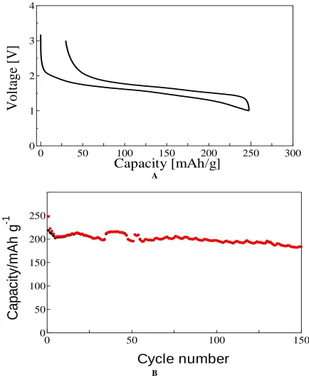
than 90%. This indicates the stability of systemized TiO2(B) material towards lithium insertion and de-insertion.
0
50
100
150
200
250
300
0
1
2
3
4
Capacity [mAh/g]
V
o
lt
ag
e
[V
]
A
0
50
100
150
0
50
100
150
200
250
Cycle number
C
a
p
a
c
ity/
m
Ah
g
-1
B
Figure 1. (a) The initial charge/discharge curves (b) cyclability of TiO2(B) electrode in 1.0 M LiPF6 -EC/DMC(1:2) solution in the voltage region of 0.0-3.0 V vs Li/Li+. The charge/discharge current density is 100 mAg-1.
[image:3.596.81.515.114.652.2]
discharge capacities of the cell are 241.9 and 93.2 mAh.g-1 respectively. Therefore the columbic efficiency of the first cycles is about 38.6 %. The low columbic efficiency in the first cycles could be attributed to the irreversible capacity associated with the PF6- anion intercalation into the MCMB and its partial exfoliation. As seen in XRD, there might be non cystalline. In addition, Meister et.al recently argued that the low columbic efficiencies in graphitic carbons occurs due to activation process of graphene layers [16] . However, during the second and subsequent cycles this irreversible capacity loss became smaller. The charge and discharge curves show bent shape mainly due to ion intercalation to the positive electrode.
0 50 100 150 200 250
0 1 2 3 4
Capacity / mAh g
–1V
o
lt
a
g
e
/
[image:4.596.120.482.228.427.2]V
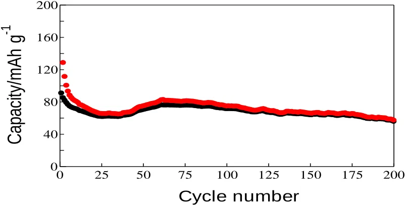
Figure 2. The first and second charge/discharge curves of the MCMB/TiO2(B) energy storage system in the voltage window of 1.0-4.0 V. The charge /discharge current density is 100 mAg-1.
0 25 50 75 100 125 150 175 200 0
40 80 120 160 200
Cycle number
C
ap
aci
ty/
mA
h
g
-1
[image:4.596.99.502.490.693.2]
As previously noticed, lithium ion interaction into the TiO2(B) electrode does not cause significant change in the shape of charge/discharge curves of the full cell. Since the charge/discharge curves are not flat, the average voltage and energy density of this device was calculated by integrating the area under the capacity/voltage profile. This calculation results indicated that the average working voltage ofthe device is 3.1 V which is significantly higher than other hybrid capacitors. According to the total weight of active materials, in the voltage region of 1.0 4.0 V, this cell delivers 142 Wh Kg-1 as energy density. Therefore, the energy density of this device is much higher than previously reported TiO2 based capacitors and EDLC's [9, 10, 16-19]. This may be due to the fact that the higher average voltage and larger discharge capacities of the working electrodes of the MCMB/ TiO2(B) ion intercalation cell.
Figure-3 exhibits charge/discharge capacities versus the cycle number of MCMB/TiO2(B) full cell at a 1.0 C rate. The charge/discharge capacities decreased for first few cycles due to electrolyte decomposition on the graphite cathode and surface film formation on the TiO2(B) anode. Therefore, after first few cycles the columbic efficiency is considerably high in this energy storage system. The capacity retention from the 5th cycle to 100th cyles is about 90 % of the initial disharge capacity.
0 5000 10000 15000 20000 25000 0
1 2 3 4 5 6
Total voltage Voltage of MCMB Voltage of TiO
2 (B)
V
olta
ge
/
V
v
s
.
Li/
Li
+
Time / s
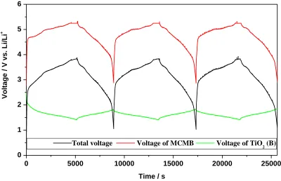
Figure 4. Potential profiles of MCMB/TiO2(B) cell during the galvanostatic charge/discharge process. The positive and negative electrodes have the same weight of active material.
[image:5.596.99.499.353.611.2]
adsorbed to the MCMB and TiO2(B) are not very large. This indicated that capacitive behaviors of the electrodes are negligible compared to that of Faradiac intercalation processes of the electrodes. This is because the surface area of MCMB and TiO2(B) are much smaller than that of activated carbon (1500-3500 m2g-1) which uses for EDLCs. In this initial absorption process, the potential of TiO2(B) negative electrode drops down to 2.0 V Li/Li+. On the other hand the potential of MCMB cathode raises up to 4.7 Vs Li/Li+. When the charging voltage increases more than 2.7 V in the full cell, the Li+ cation and PF6anions start to intercalate to TiO2(B) and MCMB respectively. This indicates that energy storage process in this cell is transferred from electric double layer electrostatic absorption to Faradaic energy storage which is also supported by XRD evidence. It was also noted from XRD data, that PF6- anions might also be intercalated to the non graphitic/disordered carbon forms in the MCMB cathode. This process also contributes to the large irreversible capacity of the first cycles.
During the charging process, the potential of TiO2(B) gradually drops down to 1.40 V Vs Li/Li+ while the MCMB electrode increases up to 5.40 V Vs Li/Li+. As it can be seen, the overall shape of the charge/discharge curves of the full cell is mainly governed by the shape of the charge/discharge curve of the MCMB because lithium ion insertion/extraction from/to the TiO2(B) is a smooth process. When lithium rich metal oxides used as cathodes, the solvation and de-solvation of lithium ions are taking place during each charge and discharge processes. The large size of the PF6 -anion causes less or no solvation effects. This process does not limit the upper cut-off voltages of MCMB/TiO2(B) dual ion intercalation cell until solvent decomposition. This allows the potential of MCMB increased up to 5.4 V vs Li/Li+ without any safely issues. As shown in 4-electrode experiment, during discharging of the full cell, the potential of TiO2(B)gradually increases from 1.4 to 1.9 V Vs Li/Li+. On the other hand the potential of MCMB drops quickly down to 5.3 then gradually decreases to 2.90 V Vs Li/Li+. These two processes maintain the voltage of this device between 10-4.0 V.
0 5 10 15 20 25 30
0 30 60 90 120 150
Charge Discharge
5.0 C
10.0 C
C
ap
acit
y
/
mA
h.g
-1
1.0 C 3.0 C
1.0 C 0.3 C
Cycle Number
[image:6.596.147.452.482.712.2]
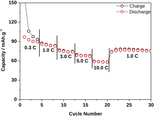
The rate performance of the constructed cell at different rates is shown in Figure.5. The charge/discharge capacities decrease with the increase of current densities similar to other reported TiO2 based capacitors [12,18-19]. At 0.3 C rate the full cell gives 92.6 mAh.g-1. With gradual increase of the current rate, the capacity drops steadily but the electrode regains its original capacity when the rate was again lowered to 1.0 C. The better rate performance of this cell mainly attribute to the structural features of TiO2(B) electrodes. In crystallographic view point, TiO2(B) has a perovskite like layered structure, comprised of edge and corner sharing TiO6 octahedra with an open channel parallel to the b-axis. This allows fast lithium insertion/de-insertion processes of the TiO2(B) materials. Due to this fast kinetics, even at relatively higher rates, the energy density of the present cell is still higher than that of EDLCs owing to the higher charging voltage and larger capacity of the working electrodes.
20 30 40 50 60
In
te
n
si
ty
2θdeg.(CuK α) A
20 30 40 50 60
In
te
n
si
ty
2θdeg.(CuK α) B
20 30 40 50 60
In
te
n
si
ty
2θdeg.(CuK α) C
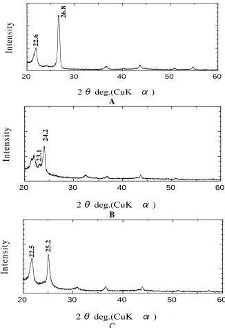
Figure 6. Ex-situ XRD patterns of the (a) Pristine MCMB electrode, (b) after the first charge (c) after first discharge processes.
2
6
.8
2
2
.6
2
4
.2
2
3
.1
2
5
.2
2
2
[image:7.596.136.462.264.739.2]
Figures 6 shows ex-situ XRD diffraction peaks of pristine, charge state and discharge state of MCMB cathode. As shown in Figure 6, the well-ordered MCMB gives very sharp peak at 26.8˚ w c is corresponding to one dimensional (002) peak indicating high crystallinity of MCMB. In addition, a b p k w (c 22 6˚ 2Ɵ) c b c b ccu c -crystalline organic materials and/or distorted carbons. This di c b c b b p k pp 3 ˚ in the XRD. When the cell charged to 4.0 V, the (002) peak splits and shifts to two peaks which are pp w XRD T p k pp 2 2˚ w r p k pp 23 ˚ T p k p w c b Therefore, the total capacity of the cathode consists of mainly from intercalation of PF6- anions into ordered and disordered graphite/carbon layers. Considering Ruch et al. calculations as shown in equation (1), the stage number (m) of graphite-anion at this stage could be assigned to 3 for anion intercalate graphite cathode. In addition, it can also be seen in the split of non-crystalline peak of MCMB. These peaks provide a profound evidence of the formation of anion-graphite intercalation compounds and insertion. Previously, Dhan et al. reported that 0.45nm of PF6− in graphene sheet, and considering the plane distance of graphite, our observations are in good agreement with the previous literature [20-23]. During discharge, the peak position of the 002 peak does not fully come back to its original position. Instead, a narrow peak appeared 25 2˚ XRD with less intensity. This observation is agreed well with electrochemical data which shows the higher irreversible capacity of the first cycle due to irreversible de intercalation of the bulk PF6- anion to the crystalline and non-crystalline graphite cathode.
m = d00(n+1) / d00n−d00(n+1) (1)
4. CONCLUSSION
In this work we presented novel ion intercalation cell, which consists of MCMB cathode and TiO2(B) anode. TiO2(B) anode facilitate fast lithium ion insertion/extraction of the cell. On the other hand TiO2 based anodes have a higher intercalation voltage which precludes lithium deposition. The MCMB cathode provides higher charging voltage of the cell without realizing oxygen from cathode side. In addition, it was also demonstrated that the long cycle life of graphitic cathodes undergoing deeper anion intercalation paves the way for development of electrochemical energy storage devices without traditional lithiated transition meta oxides. Data also show that the electrolyte could be used as the sole source of lithium ions hence improve safely features of the proposed dual ion-intercalation cell.
ACKNOWLEDEGMENT
Partial financial support from Fukuoka Industry and Science Foundation is gratefully acknowledged.
References
1. T. Aida, I. Murayama, K. Yamada, M. Morita, Electrochem. Solid State Lett. 10 (2007) A93 2. K. Naoi, P. Simon, The Electochem. Soc. Interface 17 (2008) 34.
3. H. Jurcakova, M. Seredych, Y. Jin, G. Q. Lu, T. J. Bandosz, Carbon 48 (2010) 1767. 4. S. R. Sivakumar, J. Y. Nekar, A. G. Pandolfo, Electrochim. Acta 55 (2010) 3330.
5. A. Du Pasquier, I. Plitz, J. Gural, F. Badway, G. G. Amutucci, J. Power Sources 136 (2004) 160. 6. A. Du Pasquier, I. Plitz, S. Menocal, G.G. Amatucci, J. Power Sources 115 (2004) 171.
7. V. Khomenko, E. Raymundo-Pinero, F. Beguin, J. Power Sources 177 (2003) 643.
8. R. T. Carlin, Hugh C. De Long, Joan Fuller, Paul C. Trulove, J. Elecctrochem. Soc. 47(74) (1994) L43.
9. M. Yoshio, H. Nakamura, H. Wang, Electrochem. Solid-states Lett. 9 (2006) A561. 10.H. Wang, M. Yoshio, Electrochem. Commun. 8, (2006) 1481.
11.N. Gunawardhana, G.-J. Park, N. Dimov, A. K. Thapa, H. Nakamura, H. Wang, T. Ishihara, M.Yoshio, J. Power Sources 1 (2011) 119.
12.A. K. Thapa, G.-J. Park, H. Nakamura, T. Ishihara, N. Moriyama, T. Kawamura, H. Wang, M. Yoshio Electrochimica Acta 55 (2011) 7305.
13.N. Gunawardhana, G.-J. Park, N. Dimov, A. K. Thapa, H. Nakamura, H. Wang, T. Ishihara, M.Yoshio, J. Power Sources 196(18) (2011) 7896.
14.N. Gunawardhana, G.-J. Park, N. Dimov, H. Wang, M. Sasidharan, A. K. thapa, H. Nakamura, M. Yoshio, Int. J. Electrochem. Sci 9 (2014) 195
15.J.-W Lee, H.-l Kim, H.-J. Kim, S.-G. Park, Appl. Chem. Eng. 21 (2010) 265.
16.P. Meister, V. Siozios, J. Reiter, S. Klamor, S. Rothermel, O. Fromm, H.W. Meyer, M. Winter, T. Placke, Electrochimica Acta, 130 (2014) 625
17.T. Brousse, R. Marchand , P.-L. Taberna, P. Simon, J. Power Sources 158 (2006) 571.
18.M. Sasidharan, K. Nakashima, N. Gunawardhana, T. Yokoi, M. Inoue, S.-I. Yusa, M. Yoshio, T. Tatsumi, Chem. Com. 47 (2011) 6921.
19.N. Gunawardhana, M. Sasidharan, M. Yoshio, International Conference on Power and Energy Systems (ICPES) 56 (2012) 58.
20.J. A. Seel, J. R. Dhan, J. Electrochem. Soc. 147 (2000) 892.