Low unit strength masonry: computational modelling
approaches
GIAMUNDO, VINCENZO
1; SARHOSIS, VASILIS
2; LIGNOLA, GIAN PIERO
3;
SHENG, YONG
4; GARRITY, STEPHEN
5; MANFREDI, GAETANO
6ABSTRACT:
Masonry is characterized by the large variability of its components. Parameters like strength, bond and workmanship defects strongly influence the performance of the overall structure. The applicability of different computational modelling approaches to assess the structural behaviour of masonry has been studied. Two of the most relevant computational modelling approaches have been considered namely: finite element method (FEM) and distinct element method (DEM). In order to validate the numerical outcomes, comparisons with the experimental results have been undertaken. The aim of this paper is to contribute to the knowledge and selection of a suitable modelling approach for modelling low unit strength masonry structures. The results showed that in the case of low unit strength masonry, FEM is a more suitable approach to use. In fact, since in the considered case, the block is the weak component, it is not possible to assume the brick units as a rigid block. Therefore an accurate plasticity and cracking model for the brick is required.Keywords: Masonry, wall, low unit strength, FEM, DEM, numerical analyses.
1 INTRODUCTION
Masonry is one of the oldest building materials. Masonry structures are usually made up of a large number of separate blocks bonded together by mortar in many very different arrangements. Masonry structures, especially the historical ones, are usually characterized by low strength. In particular, masonry in which the strength of the unit blocks has a dominant effect on the mechanical behaviour of the whole masonry structure is called “low unit strength masonry”. A clear example of such type of masonry is given by the constructions made of tuff blocks. Tuff is a building material used in wall constructions around the world since ancient times. Tuff is a soft, porous rock formed by the compaction and cementation of volcanic ash. Such type of structures is often encountered in southern Italy, Turkey and Japan. Furthermore, tuff masonry buildings built over the last two centuries in the Mediterranean area with load-bearing walls represent an important part of the existing buildings inventory and need to be preserved especially in seismic areas [1]. Several numerical methods and computational tools have been developed in order to study the behaviour of masonry structures. A wide range of computational methods is available today ranging from the classical plastic solution methods [2] to the most advanced non-linear computational formulations (e.g. finite element and
1)
Visiting research assistant, University of Leeds, Civil Engineering, [email protected]
2) Post doctoral fellow, Cardiff University, Civil Engineering, [email protected] 3)
Assistant professor, University of Naples Federico II, Dept. of Struct. for Eng. and Arch., [email protected]
4)
Associate professor, University of Leeds, Civil Engineering, [email protected]
5)
Hoffman wood professor, University of Leeds, Civil Engineering, [email protected]
6)
distinct element methods of analysis). The selection of the most appropriate method to adopt mainly depends on: the structural typology, the level of accuracy, time requirements and the experience of the modeller etc [3]. It should also be expected that different methods should lead to different results depending on the adequacy of the approach and the informations available. Nevertheless, the selection of a suitable method of analysis is not an easy task. In the past, several studies aimed to identify the capabilities and limitations of each method of analysis have been carried out [4-8]. None of these studies however has investigated the suitability of the method to different types of masonry.
2 AIM OF THE PAPER
Aim of this paper is to contribute to the knowledge and selection of a suitable modelling approach depending on the masonry typology. In particular, this paper is focusing on the low unit strength masonry. The study has been conducted by comparing the numerical against the experimental data. The analyses were carried out using the computational software DIANA for the application of the FEM with continuous elements and the software UDEC for the DEM. Comparisons made in respect to the suitability of the software to predict the development of the crack patterns under incremental diagonal loading. Moreover, the outcomes are compared in terms of shear stress, average diagonal strains, and average shear strain.
3 OVERVIEW ON COMPUTATIONAL MODELLING STRATEGIES
The large variability of masonry components results in a very difficult definition of limited and specific structural analysis techniques. However the mechanical behaviour of masonry structures can be investigated through different numerical strategies. Finite Element Models (FEM) and Distinct Element Method (DEM) are among the most relevant computational modelling approaches for masonry structures. Nevertheless their use in prediction analyses requires high computational effort and expert engineering judgment in the interpretation of results.
3.1. Finite element method
Different modelling approaches through FEM modelling can be adopted for masonry structures. In particular: equivalent frame [9,10,11], equivalent material approach [12,13] and micro-modelling [14,15,16]. The first is typically used to study the in plane behaviour of masonry with opening or entire structures under vertical and horizontal forces. The second approach, also known as “macro-modelling approach”, considers masonry as a homogeneous material using homogenization techniques. In micro–modelling approach, bricks and mortar are modelled separately allowing different mechanical parameters and different constitutive laws to be assumed for each material. Thereforelocal failure for both the bricks and the mortar can be simulated.
3.2. Distinct element method
rotations of the blocks are allowed with the sequential contact detection and automatic update of tasks.
4 CASE STUDY: TUFF MASONRY WALL PANELS
4.1. Brief review of the experimental tests
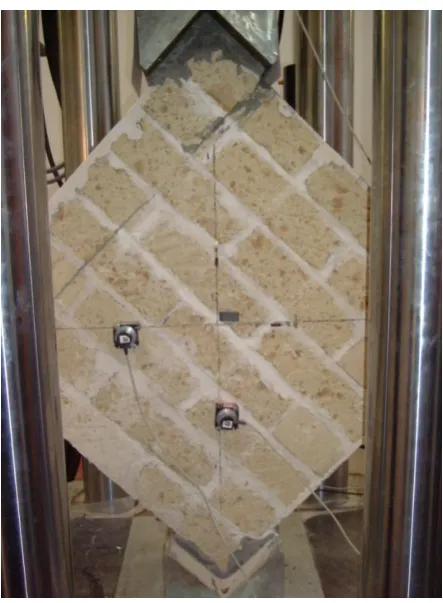
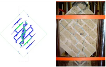
[image:3.595.201.423.276.578.2]The experimental tests were performed in the Laboratory of the Department of Structures at the University of Naples Federico II. Four tuff masonry wall panels built with the global size 1030×1030 mm2 (aspect height-to-length ratio equal to 1) and bricks size 400×110×250 mm3 were tested, under displacement control. The panels were subjected to diagonal compressive edge load forming a 45° angle with the direction of the mortar bed joints. The mortar joints layer dimension was approximately 15 mm in thickness and less than 250 mm in width (third out-of-plane dimension). Figure 1 shows the experimental setup.
The used mortar mixture was designed to reproduce typical mechanical properties of mortars used for old tuff masonry buildings. The used test setup was a modified version of ASTM [20], accounting for the dimensions of tuff blocks. In particular, two steel loading supports were placed on the two diagonally opposite corners of the panel in order to prevent a premature splitting failure of panel edges. Two LVDTs were used to measure the in-plane deformations over a gauge length of 400 mm along the diagonals. The results were analysed in terms of shear stress against average diagonal strains, and shear stress against average shear strain curves. According to ASTM standard method [20], the shear stress, τ, has been computed as τ = 0.707 V/An, were V = diagonal load and An = net section area of the uncracked section of the panel (in the considered case An = 0.092 m2). The average vertical and horizontal strains, εv and εh have been computed as the average displacement along the compressive and tensile diagonals, respectively, over the same gauge length (400 mm). The shear strain, γ, according to [20], is γ = εv+εh. The Shear modulus, G, and the Poisson ratio, ν,
were computed according to the well-known solid mechanics relationship, as ν = -εh/εv and G = τ/γ respectively. Table 1 shows the experimental results.
Table 1. Parameters for the model
Specimen ID Τ [MPa] γ [%] εv [%] εh [%] ν [-] G [MPa]
P1 0.22 0.15 -0.086 0.065 0.13 310
P2 0.35 0.11 -0.078 0.029 0.07 535
P3 0.21 0.13 -0.034 0.054 0.35 515
P4 0.19 0.15 -0.066 0.060 0.49 680
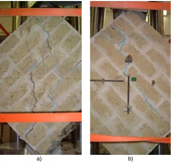
Development of initial cracks along the diagonal mortar joints are noticed in the crack pattern for all the tested panels. In particular the cracks involve both mortar and bricks; they opened along the compression strut. It is worth noting that for the panel P2, the failure was due to a combination of tensile failure of both mortar joints and tuff bricks (as shown in the Figure 2a). On the other hand for the panel P4 the cracks followed a single line of least resistance mainly through the diagonal mortar joints (as shown in Figure. 2b). These results put on evidence the big influence of the workmanship defects on the global response of the panels. A full description of the experimental diagonal compression tests on tuff masonry panels is reported by [21].
a) b)
[image:4.595.289.458.401.722.2]4.2. Numerical FEM modelling and comparison with experimental results
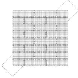
The experimental results clearly show the propagation of the crack all over the masonry panel even involving the bricks. Then a model able to simulate possible crack in the brick is needed (i.e. it is not possible to model the brick as rigid block). Micro modelling was adopted. Accurate FEM two dimensional numerical analyses have been conducted under plane-stress assumption by means of the TNO DIANA v9.1 code. The panel was modelled by eight-node quadrilateral isoparametric plane stress elements based on quadratic interpolation and Gauss integration (see the mesh in Figure 3).
Steel supports were modelled by means of three-node triangular elements. At the micro level the tuff and the mortar are modelled independently, without frictional interfaces between them [1], according to a smeared-crack approach with exponential strain softening in tension and plasticity in compression by means of a parabolic curve formulation both based on tensile and compressive fracture energy (See Figure 4).
[image:5.595.175.437.200.458.2]The tensile strength has been computed dividing the flexural strength (achieved in previous characterization tests [21]) values by 1.2, while the Poisson ratio has been assumed equal to 0.15 for all the materials. All the other parameters have been achieved as the average of the values achieved in the experimental tests [21]. Table 2 provides for the parameters used in the numerical analyses.
Figure 3. Mesh adopted in DIANA
[image:5.595.146.492.558.691.2]Table 2. Parameters used for the DIANA model
Material ft [MPa] fc [MPa] E [GPa]
Tuff 0.21 2.0 2.0
Mortar 1.31 5.0 1.8
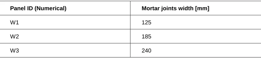
The boundary conditions assigned in the model were to represent the conditions of the laboratory test set up. Thus, the base has been fixed and the steel support has been constrained to move only in the vertical direction. According to the experimental tests numerical analyses were carried out under displacement control applying the load through the steel devices. During the analyses in-plane deformations and stress evolution were measured. Additionally the analyses have been performed also using a reduced value for the width of the mortar joints in order to simulate potentially width reduction due to the workmanship defects (i.e. mortar joints not uniformly and not fully filled). The numerical analyses programme is reported in Table 3.
Table 3. Numerical analyses programme
Panel ID (Numerical) Mortar joints width [mm]
W1 125
W2 185
W3 240
The numerical results in terms of shear strength against average shear strain, show a good match with the experimental results. In particular the smaller considered mortar filling matches the experimental behaviour of the panel P1 which presented the worse behaviour (due to the workmanship defects and variability of mortar geometrical properties). Both the fully-filled and half-filled mortar joints analyses match the behaviour of the other as-built panels. On comparison purpose numerical and experimental results are plotted in Figure 5.
[image:6.595.39.489.339.440.2]4.3. Numerical DEM outcomes and comparison with experimental results
DEM models have been created using the two dimensional numerical analyses software UDEC developed by ITASCA. Each block of the wall panel tested in the laboratory was represented by a deformable block and using UDEC’s Mohr-Coulomb plasticity constitutive model. Mortar joints were represented by zero thickness interfaces. UDEC modelling parameters have been obtained as follows: The normal stiffness (JKn) has been calculated as the ratio of the Young modulus, E, and the
0.0 0.1 0.1 0.2 0.2 0.3 0.3 0.4 0.4
0.0 0.1 0.2 0.3 0.4 0.5 0.6
S
h
ea
r
st
re
ss
τ
[M
P
a
]
Shear strain γ [%]
P1
P2
P3
P4
W1 (DIANA)
W2 (DIANA)
W3 (DIANA) W2
P3 P2
W3
P4 P1
[image:7.595.115.509.91.342.2]W1
Figure 5. Comparison of experimental against DIANA numerical results
[image:7.595.104.509.376.634.2]mortar joint thickness, t, JKn = E/t; the angle of friction (Jfric) has been computed as: Jfric = (fc-ft)/(fc+ft), where fc is the mortar compressive strength and ft is equal to Jten; the cohesive strength (Jcoh) has been computed as Jcoh = 1/2 (fcft)1/2. Table 4 and 5 shows the material properties used for the UDEC model.
Table 4. Parameters used for the blocks in the UDEC model
Density [kg/m3] E [MPa] G [MPa] Bulk Modulus [MPa] ν [-]
1427 2000 870 952 0.15
Table 5. Parameters used for the interfaces in the UDEC model
JKn [GPa/m] JKs [GPa/m] Jfric [DEG] Jcoh [MPa] Jten [MPa]
120.00 521.73 35.79° 1.27 0.21
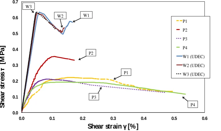
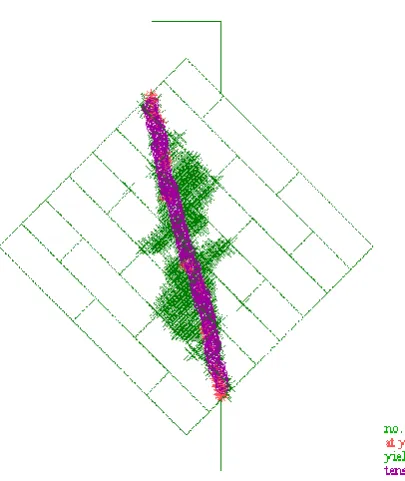
As with the FEM model, the base of the wall panel has been fixed and the steel support has been constrained to move only in the vertical direction. Also, the model was brought initially at equilibrium state. Then, external loading has been applied. According to the experimental tests, numerical analyses were carried out under displacement control applying the load through the steel devices. In particular, a constant vertical velocity was applied at the load spreader plate on the top of the wall panel. Convergence tests were carried out on the magnitude of velocity to be applied to the load support to make sure that a quasi-static loading condition was achieved. Numerical and experimental results are shown in Figure 7. Failure modes of the tuff masonry wall panel as predicted by UDEC are shown in Figure 8. The predictions overestimate the experimental outcome mainly because the brittle nonlinear behaviour of the block strongly influences and limit the performance of the wall panel. Hence, modelling low strength masonry units with DEM is not appropriate since it is not able to predict accurately the plasticity in the brittle blocks.
0.0 0.1 0.2 0.3 0.4 0.5 0.6 0.7
0.0 0.1 0.2 0.3 0.4 0.5 0.6
S h e a r st re ss τ [M P a ]
Shear strain γ [%]
[image:8.595.96.483.497.727.2]P1 P2 P3 P4 W1 (UDEC) W2 (UDEC) W3 (UDEC) P2 P1 P3 P4 W1 W2 W3
5 CONCLUSIONS
The applicability of different computational modelling approaches to assess the structural behaviour of masonry has been studied. Two of the most relevant computational modelling approaches have been considered namely: finite element method (FEM) and distinct element method (DEM). In order to validate the numerical outcomes, a comparison with the experimental results has been provided. The main purpose of the current study was to give a contribution to the knowledge and selection of a suitable modelling approach depending on the masonry typology. In particular, this paper is a first step focusing on the low unit strength masonry (tuff masonry). FEM modelling catches the experimental behaviour in terms of first crack, behaviour failure and smeared crack pattern. Conversely DEM modelling overestimates the experimental outcomes. This result can be explained by the fact that DEM model is not able to accurately model the plasticity in the block. In the case of tuff masonry, indeed, an accurate plasticity model is required in order to model the behaviour of the blocks. In conclusion, the FEM approach is a appropriate for modelling low unit strength masonry. However, at the large scale, both DEM and FEM approaches are good to model the behaviour in terms of failure mode. This study confirms and put in evidence that neither the FEM nor the DEM approach could be considered “reliable in every case”. Future activity will also involve low bond strength masonry.
REFERENCES
[1] Lignola, G.P.; Prota, A.; Manfredi, G.: Nonlinear analyses of tuff masonry walls strengthened with cementitious matrix-grid composites, J Compos Constr 2009, 13(4):243-251.
[2] Heyman, J.: Structural analysis: a historical approach, Cambridge: Cambridge University Press 1998.
[image:9.595.180.383.106.347.2][3] Lourenço, P.B.: Computations of historical masonry constructions, Prog. Struct. Engng Mater 2002, 4(3):301-319.
[4] Baggio, C.; Trovalusci, P.: Stone assemblies under in-plane actions, Comparison between non linear discrete approaches, Computer methods in structural masonry-3, Middleton J. and Pande (Eds.), G. N., BIJ, Swansea (UK), 1995, 184-193.
[5] Thavalingam, A.; Bicanic, N.; Robinson, J.I.; Ponniah, D.A.: Computational framework for discontinuous modelling of masonry arch bridges, Comput Struct 2001,79(19):1821-1830. [6] Giordano, A.; Mele, E.; De Luca, A.: Modelling of historical masonry structures: comparison of
different approaches through a case study, Engineering Structures 2002, 24:1057-1069.
[7] Zhuge, Y.: Micro-modelling of masonry shear panels with distinct element approach, Proceedings of the 17th Australian conference on the mechanics of structures and materials”, Gold Coast, Australia, 2002, 131-136.
[8] Schlegel, R.; Rautenstrauch, K.: Failure analysis of masonry shear walls, Konietzky H. editor. Numerical modelling of discrete materials in engineering, London: Taylor and Francis, 2004, p.33-42.
[9] Magenes, G.; Della Fontana, A.: Simplified non-linear seismic analysis of masonry buildings Procedings of British Masonry Society, Vol. 8, International Masonry Society, Whyteleafe, Surrey, United Kingdom, 1998, 190–195.
[10] Brencich, A.; Gambarotta, L,; Lagomarsino, S.: A macro-element approach to the three-dimensional seismic analysis of masonry buildings, Procedings of 11th European Conf. on Earthquake Engineering, Paris, France, 1998.
[11] Parisi, F.; Lignola, G.P.; Augenti, N.; Prota, A.; Manfredi, G.: Rocking response assessment of in-plane laterally-loaded masonry walls with openings, Engineering Structures 2013, 56:1234-1248.
[12] Massart, T.J.; Peerlings, R.H.J.; Geers, M.G.D.: Structural damage analysis of masonry walls using computational homogenization, Intern J of Damage Mechanics 2007, 16(2):199-226. [13] Lee, J.S.; Pande, G.N.; Middleton, J.; Kralj, B.: Numerical modelling of brick masonry panels
subject to lateral loadings. Comput Struct 1996, 61:735-745.
[14] Parisi, F.; Lignola, G.P.; Augenti, N.; Prota, A.; Manfredi, G.: Nonlinear Behavior of a Masonry Sub-Assemblage Before and After Strengthening With Inorganic Matrix-Grid Composites, J Compos Constr 2011, 15(5): 821-832.
[15] Giamundo, V. Lignola, G.P.; Prota, A.; Manfredi, G.: Diagonal strength of adobe brick walls. Proceedings of 8th International Conference on Structural Analysis of Historical Constructions, SAHC 2012, Wroclaw, Poland.
[16] Lignola, G.P.; Prota, A.; Manfredi, G.: Numerical investigation on the influence of FRP retrofit layout and geometry on the in-plane behavior of masonry walls, J Compos Constr 2012, 16(6): 712-723.
[17] Cundall, P.A.; Hart, P. A.: computer model for simulating progressive large scale movements in blocky rock systems, Proceedings of the Symposium of the International Society of Rock Mechanics 1971, Nancy, France.
[18] Lemos, J.V.: Discrete element modelling of masonry structures, Int J of Arch herit 2007; 1: 90-213.
[19] Sarhosis, V. Computational modelling of low bond strength masonry, PhD thesis, University of Leeds, 2012.
[20] American Society for Testing Materials (ASTM). Standard test method for diagonal tension (shear) in masonry assemblages. 1981, ASTM E 519-81.