This is a repository copy of
Simulation of the flow inside an annular can combustor
.
White Rose Research Online URL for this paper:
http://eprints.whiterose.ac.uk/83245/
Version: Published Version
Article:
Alqaraghuli, W, Alkhafagiy, D and Shires, A (2014) Simulation of the flow inside an annular
can combustor. International Journal of Engineering and Technology, 3 (3). 2499. 357 -
364. ISSN 2227-524X
10.14419/ijet.v3i3.2499
[email protected] https://eprints.whiterose.ac.uk/ Reuse
Unless indicated otherwise, fulltext items are protected by copyright with all rights reserved. The copyright exception in section 29 of the Copyright, Designs and Patents Act 1988 allows the making of a single copy solely for the purpose of non-commercial research or private study within the limits of fair dealing. The publisher or other rights-holder may allow further reproduction and re-use of this version - refer to the White Rose Research Online record for this item. Where records identify the publisher as the copyright holder, users can verify any specific terms of use on the publisher’s website.
Takedown
If you consider content in White Rose Research Online to be in breach of UK law, please notify us by
Simulation of the flow inside an annular can combustor
Wael Alqaraghuli 1*, Dhirgham Alkhafagiy 2, Andrew Shires 3
1
Depart. of Mechanical Eng., MSc Scholar, Babylon University
2Depart. of Mechanical Eng., Assistant Prof., Babylon University
3
Depart. of Offshore, Process and Energy Eng., Senior Lecturer, Cranfield University
*Corresponding author E-mail: [email protected]
Copyright © 2014 Wael Alqaraghuli et al. This is an open access article distributed under the Creative Commons Attribution License, which permits
unrestricted use, distribution, and reproduction in any medium, provided the original work is properly cited.
Abstract
In the gas turbine combustion system, the external flows in annuli play one of the key roles in controlling pressure loss, air flow distribution around the combustor liner, and the attendant effects on performance, durability, and stability. This paper describes a computational fluid dynamics (CFD) simulation of the flow in the outer annulus of a can combustor. Validating this simulation was done with experimental results obtained from analyzing the flow inside a can combustor annulus that was used in a Babylon/Iraq gas turbine power station. Pitot static tubes were used to measure the velocity in ten stations in the annular region. By using the velocity profile for comparison, a good agreement between the CFD simulation and experimental work was observed.
Nomenclature:
R: radius of combustor (mm) r: local radius (mm)
Pt: total pressure (Pascal) Ps: static pressure (Pascal) DG: damp gap (mm)
X/Dc: axial distance is normalized with the diameter of the casing as the origin. A, B and L: station of measurement and investigated locations.
u: local axial velocity
U: mass average axial velocity at inlet
Keywords: Annulus Flow, Can Combustor, CFD Simulation, Pitot Static Tube, Velocity Profile.
1.
Introduction
A can combustor is an integral part of a gas turbine power unit. It receives air from a compressor and delivers it to the turbine at an elevated temperature; it is highly desirable to have this done with better overall efficiency and smoke free combustion.
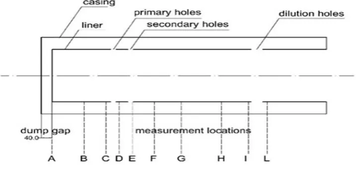
In general the combustor has three main components: i) diffuser, ii) casing-liner annulus, and iii) liner. Figure (1) shows the main parts of the can combustor.
The present paper, investigated the flow characteristic inside a can annular combustor computationally and experimentally, and developed a simulation to study more effective cases on the performance of combustor cooling and penetration of the air to complete the combustion inside the liner.
358 International Journal of Engineering & Technology
Fig. 1: Can Combustor Layout
Koutmos and McGuirk [1] modelled flow in the axisymmetric cone position tested by Fishenden and Stevens [2] and found that their predictions were of sufficient accuracy for engineering purposes. The studied models were the following: standard, RNG, realizable, Durbin modified, and the nonlinear k- model. The results showed that the standard and Durbin k- models gave the best agreement with the experimental data. This supported the findings of Wennerberg and Obi [3] where good agreement between the k- model predictions and experimental results were reported.
Mohan, Singh and Agrawal [4] have numerically investigated annuli flow and the effect of inlet swirl on the flow split through the liner holes of an annular reverse flow combustor model.
Garg et al. [5] have reported the effect of the height of inner and outer annuli for an elliptical dome shape combustor for cold flow simulation using CFD.
Miao and Wu [6] conducted numerical investigations on flat, three-dimensional, discrete-hole film cooling geometries that included the main flow, injection tubes, impingement chamber, and supply plenum regions. They found that the predicted data for a low-Reynolds k- turbulence model fitted closely with the experimental data.
Barringer et al. [7] also tested and computationally modelled a non-reacting combustor simulator containing liners with film cooling holes and two rows of in-line dilution jets that produced similar turbulence intensity levels near 18%. The computational models used the RNG k- turbulence model and the results agreed with those found by Holdeman [8] in that turbulence was under-predicted.
Alkhafagiy and Rahim [9], investigated the design of can combustors with non-swirling and swirling flows at the inlet which they considered for analysis in an isothermal environment, through CFD study. They show that the numerical results which are validated against the experimental results are reasonable. Rahim, Singh and Veeravalli [10], studied the annulus flow characteristics of a can combustor model for different liner dome shapes which have been experimentally established under isothermal flow conditions for both non-swirling and swirling flow; they found that swirling flow with a hemispherical dome liner gives better flow characteristics in the annulus region.
2.
Experimental facility
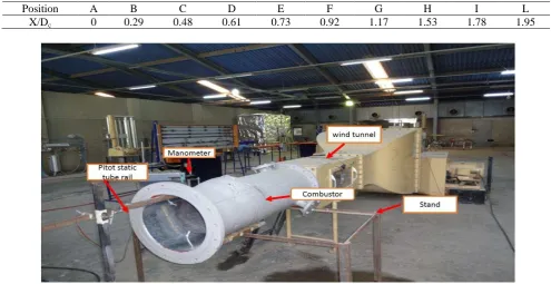
The can combustor that has been studied was a real part of Babylon gas turbine power station - Iraq. This part was brought to the laboratory and connected it to supersonic wind tunnel, which has square section. Since the combustor has circular section, a wood shell has been placed between the wind tunnel outlet and the combustor inlet. This wood shell shows a circular hole that allows matching the square and circular sections. Figure1 shows the experimental set-up in the lab. The wind tunnel supplied the air to the combustor at atmospheric pressure and the velocity 31m/s and temperature 314k. Figure (2) shows the Experimental setup. The geometrical details of can-annulus combustor consist of a cylindrical air casing of diameter 410mm and length 1060mm and internal liner with diameter 280mm and length 1020mm.
Position A B C D E F G H I L
X/Dc 0 0.29 0.48 0.61 0.73 0.92 1.17 1.53 1.78 1.95
Fig. 2: Experimental Setup
3.
Computational model
[image:4.595.49.545.80.335.2]A commercial available CFD code ‘FLUENT’6.3 has been used for the analysis. The can combustor was developed from 2-D geometry using GAMBIT package of the FLUENT code. At the inlet of combustor, velocity flow deduced from measured data, were specified. Outlet from the combustor is the total pressure (from primary and secondary and dilution holes and the end of combustor) this specified pressure was determined from measured data. The air is the working fluid; figure (3) shows the boundary conditions in the CFD simulation.
Fig. 3: Flipchart Shows the Boundaryconditions in CFD
[image:4.595.76.516.455.592.2]360 International Journal of Engineering & Technology
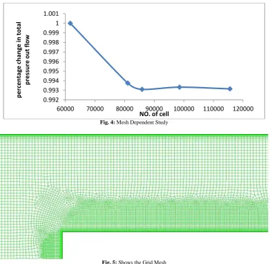
Fig. 4: Mesh Dependent Study
Fig. 5: Shows the Grid Mesh
4.
Results and discussion
The flow characteristics in the annular can combustor have been studied experimentally and theoretically. Figures (6A to 6L) show the experimental and theoretical simulation results of axial velocity profile in the outer annular.
It is observed that there is a good agreement between the experimental and theoretical results despite of some accepted differences between these results of the velocity profile. Whereas it is noticeable that at the beginning of the annular region of the combustor (start from point A) the velocity profiles are not uniform and it does not have the full shape of the known velocity profile this is due to the disturbance that happened to the flow at the beginning of its path. The sharp edge of the liner head (dome)it has negative effect on the flow uniformity which generate big recirculation region and
revers flow near the liner wall, that’s appear in figure (6B) and (6D). However as it is got towards the end of the
combustor from figure (6C to 6L) the flow become more and more uniform to give the good representing to the theoretical profile of the velocity.
0.992 0.993 0.994 0.995 0.996 0.997 0.998 0.999 1 1.001
60000 70000 80000 90000 100000 110000 120000
p
e
rc
e
n
ta
g
e
c
h
a
n
g
e
i
n
t
o
ta
l
p
re
ss
u
re
o
u
t
fl
o
w
Axial Velocity profile at (A) Axial velocity profile at (B)
Axial velocity profile at (C) Axial velocity profile at (D)
0.6 0.65 0.7 0.75 0.8 0.85 0.9 0.95 1 1.05
0.25 0.45 0.65 0.85 1.05
r/ R u/U Simulation exp 0.6 0.65 0.7 0.75 0.8 0.85 0.9 0.95 1 1.05
0.3 0.5 0.7 0.9 1.1
r/ R u/U simulation exp 0.6 0.65 0.7 0.75 0.8 0.85 0.9 0.95 1 1.05
0.15 0.35 0.55 0.75 0.95 1.15
r/ R u/U simulation exp 0.6 0.65 0.7 0.75 0.8 0.85 0.9 0.95 1 1.05
0.4 0.6 0.8 1 1.2
r/
R
u/U
simulation
362 International Journal of Engineering & Technology
Axial velocity profile at (E) Axial velocity profile at (F)
Axial velocity profile at (G) Axial velocity profile at (H)
0.6 0.65 0.7 0.75 0.8 0.85 0.9 0.95 1 1.05
0.4 0.6 0.8 1 1.2
r/ R u/U simulation exp 0.6 0.65 0.7 0.75 0.8 0.85 0.9 0.95 1 1.05
0.4 0.6 0.8 1 1.2
r/ R u/U simulation exp. 0.6 0.65 0.7 0.75 0.8 0.85 0.9 0.95 1 1.05
0.4 0.9 1.4
r/ R u/U simulation exp 0.6 0.65 0.7 0.75 0.8 0.85 0.9 0.95 1 1.05
0.5 0.7 0.9 1.1
r/
R
u/U
simulation
Axial velocity profile at (I) Axial velocity profile at (L)
Fig. 6: Shows the Comparison Between the CFD Simulation and Experimental Work.
[image:8.595.63.539.68.358.2]After it has ensured from the agreement between the theoretical and experimental results, it will be useful to study the other characteristics of the flow that have an effects on the performance of combustor work. Figure (7) shows contours of the velocity magnitude.it is observed big recirculation region at beginning of annuls flow and high level of velocity magnitude near the casing wall, this effect on penetration of air through the holes and cooling the liner wall performance. When arrives to the dilution holes the velocity decrease and will be uniform until the end.
Fig.7: Contours of Velocity Magnitude
Figure (8) shows the turbulent intensity. The turbulent at entrance of annuli is very high especially at the corners and then the turbulent decrease gradually to arrive at the end of combustor. The higher turbulence level produces more uniform profiles, reduce the pressure loss, and reduce the likelihood of flow separation.
0.6 0.65 0.7 0.75 0.8 0.85 0.9 0.95 1
0.4 0.6 0.8 1 1.2
r/
R
u/U
simulation
exp.
0.6 0.65 0.7 0.75 0.8 0.85 0.9 0.95 1
0.5 0.7 0.9 1.1
r/
R
u/U
Simulation
[image:8.595.64.532.397.666.2]364 International Journal of Engineering & Technology
Fig. 8: Contours of Turbulent Intensity
5.
Conclusion
The flow characteristics of can combustor have been studied experimentally and theoretically. It has been found that the velocity extremely affected as well as the pressure that will effect on the performance of the combustor and finally on the output power of the plant in general. The experiment took place on a real combustor that had been used in the power plant of Babylon Electrical power station. Then the experimental and the FLUENT simulation results were validated. The validation appear the CFD is a good tool for combustor flow analysis and the standard k- model gives reasonable predication of the flow in the annular can combustor.
Acknowledgements
The authors would like to thank the Cranfield University, School of Engineering, Offshore, Process and Energy Engineering for the use of their facilities. They would further like to thank the Babylon gas turbine power station for providing assistance in completing this work.
References
[1] Koutmos, P. and McGuirk, J.J. (1989), Isothermal flow in a gas-turbine combustor—a benchmark experimental study. Experiments in Fluids 7(5), pp. 344-354. http://dx.doi.org/10.1007/BF00198453.
[2] Fishenden, C.R. and Stevens, S.J. (1977), Performance of annular combustor dump diffusers, Journal of Aircraft, 14(1), pp. 60-67. http://dx.doi.org/10.2514/3.58749.
[3] Wennerberg, D. and Obi, S. (1993), Prediction of strongly swirling flows in quarl expansions with a non-orthogonal finite-volume method and a second-moment turbulence closure. In: Rodi, W. and Martelli, F. (eds.) Engineering Turbulence Modelling and Experiments, vol. 2, pp. 197-206. ISBN 0444898026.
[4] Mohan, R., Singh, S.N. and Agrawal, D.P. (1995), Flow split in a reverse flow combustor, Proceedings of the 22nd National Conference on Fluid Mechanics & Fluid power (IIT, Madras), 182-186.
[5] Garg, G., Bharani, S., Singh, S.N. and Seshadri, V. (2011), Flow characteristics around the liner of an annular gas turbine combustor model, Proceedings of the 28th National Conference on Fluid Mechanics & Fluid Power (PEC, Chandigarh) 13-15 Dec, pp. 3-11.
[6] Miao, Jr. M. and Wu, C-Y. (2006), Numerical approach to hole shape effect on film cooling effectiveness over flat plate including internal impingement cooling chamber. International Journal of Heat and Mass Transfer, 49, pp. 919-938. http://dx.doi.org/10.1016/j.ijheatmasstransfer.2005.09.015.
[7] Barringer, M., Richard, O., Stitzel, S., Walter, J. and Thole, K. (2002), "Flow Field Simulations of a Gas Turbine Combustor," Journal of Turbo Machinery, 124, pp. 508-516. http://dx.doi.org/10.1115/1.1475742.
[8] Holdeman, J.D. (1993), Mixing of Multiple Jets with a Confined Subsonic Crossflow, Progress in Energy and Combusion Science, 19, pp. 31-70, 60-67.
[9] Alkhafagiy, D. and Rahim, A. (2007), Application of CFD in combustor design technology, National Conference on State of Art Technologies in Mechanical Engineering, STEM, and pp. 311-316.