This is a repository copy of Effect of starting microstructure upon the nucleation sites and distribution of graphite particles during a graphitising anneal of an experimental
medium-carbon machining steel.
White Rose Research Online URL for this paper: http://eprints.whiterose.ac.uk/86918/
Version: Accepted Version
Article:
Inam, A, Drummond-Brydson, R and Edmonds, DV (2015) Effect of starting microstructure upon the nucleation sites and distribution of graphite particles during a graphitising anneal of an experimental medium-carbon machining steel. Materials Characterization, 106. 86 - 92. ISSN 1044-5803
https://doi.org/10.1016/j.matchar.2015.05.014
© 2015, Elsevier. Licensed under the Creative Commons Attribution-NonCommercial-NoDerivatives 4.0 International http://creativecommons.org/licenses/by-nc-nd/4.0
[email protected] https://eprints.whiterose.ac.uk/
Reuse
Unless indicated otherwise, fulltext items are protected by copyright with all rights reserved. The copyright exception in section 29 of the Copyright, Designs and Patents Act 1988 allows the making of a single copy solely for the purpose of non-commercial research or private study within the limits of fair dealing. The publisher or other rights-holder may allow further reproduction and re-use of this version - refer to the White Rose Research Online record for this item. Where records identify the publisher as the copyright holder, users can verify any specific terms of use on the publisher’s website.
Takedown
If you consider content in White Rose Research Online to be in breach of UK law, please notify us by
Effect of Starting Microstructure upon the Nucleation Sites and Distribution of Graphite Particles during a Graphitising Anneal of an Experimental Medium-Carbon Machining Steel
A. Inam a, R. Brydson a and D.V. Edmonds a
a
Institute for Materials Research
School of Chemical and Process Engineering University of Leeds
Leeds, LS2 9JT United Kingdom
Author email addresses: aqil inam [[email protected]]; Rik Brydson
[[email protected]]; David Edmonds [[email protected]]
Corresponding Author:
David V Edmonds FREng FIMMM CEng CSci FASM
Professor Emeritus and Visiting Research Professor
Institute for Materials Research
School of Chemical and Process Engineering
University of Leeds
Leeds LS2 9JT
United Kingdom
tel: +44 (0)113 343 2426 (Institute Secretary: Marie Gray)
fax: +44 (0)113 343 2384
email: [email protected]
Abstract
The potential for using graphite particles as an internal lubricant during machining is
considered. Graphite particles were found to form during graphitisation of experimental
medium-carbon steel alloyed with Si and Al. The graphite nucleation sites were strongly
influenced by the starting microstructure, whether ferrite-pearlite, bainite or martensite,
as revealed by light and electron microscopy. Favourable nucleation sites in the
ferrite-pearlite starting microstructure were, not unexpectedly, found to be located within
pearlite colonies, no doubt due to the presence of abundant cementite as a source of
carbon. In consequence, the final distribution of graphite nodules in ferrite-pearlite
microstructures was less uniform than for the bainite microstructure studied. In the case
of martensite, this study found a predominance of nucleation at grain boundaries, again
leading to less uniform graphite dispersions.
Highlights
The potential for using graphite particles as an internal lubricant during the machining of carbon steels is explored via the metallography of their formation during a high temperature anneal of an experimental steel composition.
The influence of the pre-anneal starting microstructure on the nucleation sites of the graphite particles is demonstrated.
The influence of the pre-anneal starting microstructure on the distribution of the graphite particles is also investigated.
These microstructural features are expected to be influential on whether graphite particles, rather than carbide particles, would improve machinability, thus allowing beneficial new free-cutting steel compositions to be developed without enhanced or special alloying additions such as Pb.
1. Introduction
Steel is a high volume industrial material and in consequence, to enable rapid forming and
also minimise costs, various steels have been developed which allow machining at higher
cutting speeds [1,2]. Known as free-cutting or free-machining steels these steel grades
generally contain enhanced or special alloying additions (e.g. Pb, S, P, Bi, Se, Te) which can
make them difficult to process or re-cycle, and as more stringent health and safety legislation
is introduced might eventually lead to their restriction or total prohibition from certain
manufactured products [1-5]. Consequently, should more process- and user-friendly
economic alternatives be discovered it is most likely that their adoption would quickly
follow. One simple alternative, if a steel chemistry and process route compatible with
high-volume mass production can be devised, is to use carbon in its equilibrium form, graphite, as
an internal lubricant [e.g. 5]. The present article reports upon part of a project to develop
experimental machining steels designed to graphitise during a relatively short anneal [6-17].
Thus it has been demonstrated that the kinetics of graphitisation can be markedly accelerated
by deliberately alloying medium-carbon steel with the graphitising elements Si and Al. The
primary objective of this part of the study is to determine the effect of starting microstructure
upon the nucleation sites and distribution of graphite particles in three starting
microstructures; ferrite-pearlite, bainite and martensite. At present, there is no such data
available comparing the effect of starting microstructure on the graphite nucleation sites and
their distribution, which may influence machinability, in carbon steels. In consequence, a
detailed microstructural characterisation study was carried out using light optical and electron
microscopy techniques. Comparisons between the influence of the different starting
microstructural conditions on graphite dispersion and hence machinability will be reported
elsewhere.
*Text Only in MS Word (Double-Spaced)
2. Material and Methods
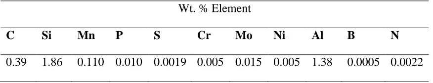
The experimental steel studied was a medium-carbon steel containing relatively high Si and
Al content and was prepared as a 60 kg heat at Tata Steel, Rotherham, UK. The analysis is
given in Table 1.
The ingots produced were hot-rolled to plate of 12 mm thickness. In order to perform the
various heat-treatments for microstructural study, small specimens ~10 mm3 were cut using a
Struers Discotom 2 cutter flooded with cooling fluid to prevent specimen heating. A
heat-resistant Oxy-Stop 2200 coating to assist with protection against mill-scale (iron oxide)
formation was also used.
Three typical starting microstructural conditions were considered:
Ferrite/pearlite (as-received hot-rolled and normalised condition).
Bainite (austenitised 1150 °C for 7 minutes and austempered at 400-420 °C
for 60 minutes in a nitrate salt bath).
Martensite (austenitised 1150 °C for 7 minutes and water quenched).
Samples for metallographic study were then annealed (tempered) at 680 ºC for increasing
times (~20 minutes to ~720 minutes (12 hours)).
For microscopic analysis by light and scanning electron microscopy specimens were prepared
by standard metallographic procedures before etching in 2% Nital. The light optical
microstructural study was carried out using an Olympus BX51 microscope and digital
micrographs recorded with an AxioCam MRc 5 (Carl Zeiss) camera attached to the
microscope. Specimens prepared for light optical microscopy were also used for secondary
Gemini FEGSEM equipped with an energy dispersive X-ray spectrometer. SE imaging and
EDX were carried out at 10 kV.
3. Results and Discussion
3.1 Light Optical Microscopy
3.1.1 Ferrite-Pearlite Starting Microstructure
Micrographs of un-etched and etched microstructures showing the sequence of graphitisation
from the ferrite-pearlite starting microstructure of the experimental steel are presented in Fig.
1. The typical ferrite-pearlite starting microstructure before annealing can be seen in Fig.
1(a). The coarse and irregular morphology of the individual particles or nodules formed is
distinctive of graphite, as observed by separate studies of this experimental steel composition
(6-17), as well as being suggestive of early nucleation at inclusion particles in the steel.
The sequence of micrographs in Fig. 1 also shows evidence for spheroidisation of lamellar
pearlitic cementite within the pearlite regions and its eventual dissolution, and the formation
of an equiaxed ferrite matrix from the original starting microstructure. After 8 hours this
process appears to be complete with little carbide observable by light optical microscopy and
only coarse graphite particles inhabiting an equiaxed ferrite matrix.
A graphite particle embedded in a pearlite colony, as shown in Fig. 1(b), is typical and
indicates these as favoured nucleation sites, given the proximity to the cementite as the
source of carbon, and also the lamellae boundaries as diffusion pathways. However, also
evident from closer inspection is that many of the coarse graphite nodules in the
ferrite-pearlite microstructure contain particles near their centre, as can be seen, for example, in
Figs. 1(b), (f) and (g)). It is known that graphite can nucleate on particles, often nitrides or
oxides [18-20]. These are often the first nucleation sites to operate, and lead to a coarse
coarsening carbide particles, as suggested and investigated by He et al. [6-16], are not
activated this will be the final form of dispersion, which appears to be the case in the
ferrite-pearlite starting microstructure. However, it is then interesting to speculate as to why, if the
nucleation is promoted by such nucleating particles, so many of the nodules grow in
association with the pearlite regions. This may be because a majority of nucleating particles
exist in these regions, or that there is competition for carbon in the early stages of nucleation
and growth, with the nodules located in pearlite regions dominating because of the
dissolution of the high volume fraction of cementite as the principle source of carbon.
The micrographs in Fig. 1 also contain clear evidence for association of the graphite particles
with ferrite grain boundaries, and so it is likely that these influence strongly the nodule
growth and largely contribute to the irregular morphology during the later stages of growth.
3.1.2 Bainite Starting Microstructure
The bainite microstructure developed at 400 ºC in the experimental steel is shown in Fig. 2(a)
and a magnified image of the cluster of ferrite plates from the outlined region reproduced in
Fig. 2(b). The roughly parallel packets of ferrite plates, visible in Fig. 2(b), are also referred
to as sheaves and have a length ~10 µm. These feathery ferrite crystals revealed in Fig. 2
were identified as upper-bainite microstructure according to previous metallographic studies
as, for example, reviewed recently by Furuhara [21], and Caballero for steels with enhanced
Si concentrations [22]. From detailed observations by high-resolution electron microscopy
made by He et al. [6-16] it is assumed that tempering bainitic carbides, which would be
coarsening rapidly during the graphitising anneal, can act as the nuclei for graphite particles,
thus leading to the apparently more refined graphite dispersion obtained as compared with the
ferrite-pearlite starting microstructure. Etched microstructures, developed after 30 minutes
and 4 hours of graphitising anneal from the bainite starting microstructure, are presented in
These reveal a similar graphite size and distribution suggestive that little further
graphitisation occurs after the shorter anneal. The graphite particles are more regular in
morphology and the dispersion is more refined and relatively uniform as compared with that
generated from the ferrite-pearlite starting microstructure. The relatively rapid grain growth
of an equiaxed ferrite matrix from the initial bainite can also be noted.
3.1.3 Martensite Starting Microstructure
Fig. 3(a) shows lath martensite developed after water quenching the experimental steel from
1150 ºC and a magnified image from the region outlined is reproduced in Fig. 3(b). This form
of martensite is consistent with a report by Maki [23] that this lath martensite morphology,
rather than a thin plate one, is only produced at high austenitising temperatures. The
martensite laths are indicated by arrowheads in Fig. 3(b), and as far as can be determined at
the resolution of the light optical microscope, appear to have widths ~0.5 µm, also consistent
with detailed metallography by Maki [23]. The etched microstructures developed after 30
minutes and 1 hour of graphitising anneal are shown in Figs. 3(c) and (d), respectively. It
appears very clear from this set of micrographs that the graphite particles were not uniformly
distributed in the ferrite matrix but positioned at present or previous positions of grain
boundaries. It is expected that this striking observation of grain boundary precipitation of
graphite in the martensite starting microstructure would have an influence on grain size by
pinning ferrite grain boundaries during growth. Certainly this distribution of graphite is very
different to that in the most comparable alternative starting microstructure of bainite.
Nonetheless, comparison of Figs. 2 and 3 does not give the impression of a refined ferrite
microstructure from martensite as compared with bainite, although these micrographs have
been selected to present different features. But this mode of graphite precipitation is a new
observation because such distinctive formation along grain boundaries has not been reported
previously. In consequence, this distribution and its effect upon ferrite grain size during the
graphitization anneal is clearly a subject for more detailed research.
The size range of the graphite particles, however, is more similar to that also developing from
annealing times. It is possible that some coalescence of graphite is beginning to occur by
coarsening along the boundaries, although it was not possible to confirm this due to limited
resolution of the light optical microscope. However, it should be mentioned that this strong
association of graphite nucleation confined mainly to the grain boundary regions of the
martensite starting microstructure was not apparent during previous investigations of this
experimental steel [6-16] and so it is likely that a more uniform dispersion of graphite
particles, more similar to that of the bainite starting microstructure, should also be possible.
The microstructural sequence observed above relates most directly to the later stage of
martensite tempering at elevated temperature (in this specific case 680 ºC) as recently
described, for example, by Krauss [24] and also by Maki [23]. However, it is assumed that all
of the previous well-known stages of tempering also described would have occurred rapidly
during the heating cycle or earlier than the first observation of the appearance of graphite.
Thus it is expected that the graphite forms within a fully-tempered near-equiaxed matrix of
ferrite. However, the experimental steel has been designed to contain relatively high
concentrations of Si and Al which favour graphitisation rather than stabilisation of carbides.
In consequence, recent studies [e.g. 16] discovered, using principally TEM/EELS techniques,
that the coarse particles formed in martensite in this composition of steel by tempering at
high temperatures are not fully crystalline cementite but can contain a more amorphous
structure, rich in carbon. Thus it is thought that these tempering particles can act as a
transitional phase which forms the initial nuclei for graphite, and moreover, are more
numerous than the larger nitride or oxide particles which can also operate, as seen above, in
the case of ferrite-pearlite structure. Consequently, these particles lead to a finer dispersion of
smaller graphite particles. He et al. [e.g. 16] have also produced fairly persuasive
metallographic evidence that the small spherical graphite nodules ≤5 m diameter which are
a more amorphous core, more representative of the transitional partly-amorphous particles
mentioned above.
3.1.4 Shape, Size and Distribution of Graphite Particles
The significant differences in graphite particle shape, size and distribution between the three
starting microstructures are readily apparent from the micrographs. This is confirmed by the
majority of maximum graphite particle diameters achieved in the fully graphitised state,
measured approximately, as ferrite/pearlite ~10-20 µm; bainite ~5 µm; martensite ~1-2 µm.
3.2 Scanning Electron Microscopy
Scanning electron micrographs and accompanying qualitative EDX analysis of suspected
graphite particles formed after 30 minutes of graphitising anneal from starting
microstructures of ferrite-pearlite, bainite and martensite, are presented in Figs. 4(a), (b) and
(c), respectively.
The EDX spectra provide additional experimental evidence that the particles or nodules
examined in detail by light optical microscopy, as reported above, during the characterisation
of microstructural evolution of the experimental steel during annealing the three different
starting microstructures at 680 ºC, are graphite phase, and not carbide. This is consistent with
previous studies of this experimental steel composition [6-17].
4. Conclusions
Light optical and electron microscopic study revealed that the graphite dispersions and final
ferrite matrix resulting from a graphitising anneal of the experimental steel at 680 ºC were
strongly influenced by the starting microstructures viz., ferrite-pearlite, bainite or martensite.
Graphite dispersion was identified in all three starting microstructures of the
experimental steel by light optical microscopy of un-etched surfaces, by EDX analysis
in SEM after only 30 minutes of annealing.
The micrograph sequences strongly indicated that the favoured location for
graphite particle nucleation in ferrite-pearlite starting microstructure was the pearlite
regions and in the martensite starting microstructure was associated with the grain
boundaries. In the bainite starting microstructure precipitation of larger graphite
particles (~5 µm) were evident at the bainitic ferrite plate boundaries.
For the experimental steel in the conditions examined, a more uniform
distribution of the graphite particles resulted from the bainite starting microstructure,
whilst the graphite nucleation behaviour revealed for the ferrite-pearlite and
martensite starting microstructures resulted in non-uniform dispersions.
Acknowledgements
We are grateful to Tata Steel, Rotherham, UK, for providing the experimental steel for this
investigation. Aqil Inam is also indebted to the University of the Punjab, Lahore, Pakistan for
financial support whilst undertaking this research.
References
[1] Trent EM, Wright PK. Metal cutting. 4th ed. Boston: Butterworth-Heinemann; 2000.
[2] Childs THC, Maekawa K, Obikawa T, Yamane Y. Metal machining: Theory and
[3] Lampman SR, Zorc TB. Properties and selection: Irons, steels and high performance
alloys; Metals Handbook. Materials Park, OH: ASM International; 1990.
[4] Akasawa T, Sakurai M, Nakamura M, Tanaka T, Takano K. Effects of free-cutting
additives on the machinability of austenitic stainless steels. Mater Proc Technol
2003;143-144:66-71.
[5] Iwamoto T, Hoshino T, Amano K, Nakano Y. An advanced high strength graphitized
steel for machining and cold forging uses. In: Van Tyne CJ, Krauss G, Matlock DK, editors.
Fundamentals and applications of microalloying forging steels. Warrendale, PA:
TMS/Minerals, Metals and Materials Society; 1996, p. 277-86.
[6] He K, Edmonds DV. On the formation of graphite nodules in the solid-state. In: Cross R,
Witcomb M, editors. 15th international congress on electron microscopy, Durban, South
Africa, 2002. Proceedings Vol. 1 Physical, materials and earth sciences. Microscopy Society
of Southern Africa; 2002, p. 719-20.
[7] He K, Edmonds DV. A high-resolution electron microscope study of the growth structure
of graphite nodules in steel. In: Cross R, Witcomb M, editors. 15th international congress on
electron microscopy, Durban, South Africa, 2002. Proceedings Vol. 1 Physical, materials and
earth sciences. Microscopy Society of Southern Africa; 2002, p. 667-8.
[8] He K, Brown A, Brydson R, Daniels HR, Edmonds DV. Plasmon ratio mapping of
congress, Antwerp, Belgium, 2004. Vol II Materials sciences. Liege: Belgian Society for
Microscopy; 2004, p. 591-2.
[9] Green MJW, Reynolds PE, He K, Edmonds DV. Graphitisation of medium-carbon steel.
In: Proceedings: Materials science and technology 2004, vol. I Precipitation in steels –
Physical metallurgy and property development. Warrendale, PA:AIST/The Minerals, Metals
and Materials Society; 2004, p. 207-15.
[10] Edmonds DV, He K. The graphitisation process in medium-carbon steel. In: Howe JM,
Laughlin DE, Lee JK, Dahmen U, Soffa WA, editors. Proceedings: Solid-to-solid phase
transformations in inorganic materials 2005 - Vol 1: Diffusional transformations. Warrendale,
PA: TMS/The Minerals, Metals & Materials Society; 2005, p. 53-8.
[11]. He K, Edmonds DV. Acceleration of graphitisation in carbon steels to improve
machinability. In: Proceedings: Super-high strength steels, 2005, Rome. Associazione
Italiana di Metallurgia (AIM)/Centro Sviluppo Materiali (CSM): ISBN 88-85298-56-7
(CD-ROM); 2005.
[12] He K, Brown A, Brydson R, Edmonds DV. An EFTEM study of the dissolution of
cementite during the graphitisation annealing of a quenched medium carbon steel. In:
EMAG-NANO 2005: Imaging, analysis and fabriation on the nanoscale. Electron microscopy
and analysis group conference, Leeds, 2005. J Physics: Conference Series 26. Bristol: IOP
[13]. He K, Edmonds DV. A potential graphitization route to improved machinability of
carbon steels. In: International conference on new developments in long and forged products:
Metallurgy and applications. Winter Park, Colorado, 2006. Warrendale, PA: AIST; 2006, p.
49-56.
[14] Edmonds DV, He K. Graphitization as a potential route to improved machinability of
carbon steels. In: 61st ABM Annual Congress, Rio de Janeiro, Brazil; 2006. Sao Paulo:
Associação Brasileira de Metalurgia, Materiais e Mineração (ABM); 2006, p. 2535-44.
[15]. He K, Brown A, Brydson R, Edmonds DV. Analytical Electron Microscope Study of
the Dissolution of the Fe3C Iron Carbide Phase (Cementite) During a Graphitisation Anneal
of Carbon Steel. J Mater Sci 2006;41:5235-41.
[16] He K, Daniels HR, Brown A, Brydson R, Edmonds DV. An electron microscopic study
of spheroidal graphite nodules formed in a medium-carbon steel by annealing. Acta
Materialia 2007;55:2919-27.
[17] Inam A, Edmonds DV, Brydson R. Heterogeneous nucleation of graphite in carbon steel.
In: Stokes DJ, Rainforth WM, editors. Proceedings: 15th European microscopy congress,
Manchester, 2012.Oxford: Royal Microscopical Society; 2012, p. 495-6.
[18] Oikawa K, Abe T, Sumi S. Medium-carbon steel having dispersed fine graphite structure
and method for the manufacture thereof. Patent 6174384, United States of America, 2001.
[19] Tanaka R, Yamane Y, Sekiyab K, Narutakib N, Shiragac T. Machinability of BN
free-machining steeel in turning. Int J Machine Tools & Manufacture 2007;47:1971-7.
[20] Banerjee K, Vanugopalan T. Development of hypoeutectoid graphitic steel for wires.
Mater Sci Technol 2008;24:1174 - 8.
[21] Furuhara T. Carbide-containing bainite in steels. In: Pereloma E, Edmonds DV, editors.
Phase transformation in steels Volume 1: Fundamentals and diffusion-controlled
transformations. Cambridge: Woodhead Publishing; 2012, p. 417-35.
[22] Caballero FG. Carbide-free bainite in steels. In: Pereloma E, Edmonds DV, editors.
Phase transformation in steels Volume 1: Fundamentals and diffusion-controlled
transformations. Cambridge: Woodhead Publishing; 2012, p. 436-67.
[23] Maki T. Morphology and substructure of martensite in steels. In: Pereloma E, Edmonds
DV, editors. Phase transformation in steels Volume 2: Diffusionless transformations, high
strength steels, modelling and advanced analytical techniques. Cambridge: Woodhead
Publishing; 2012, p. 34-58.
[24] Krauss G. Tempering of martensite in carbon steels. In: Pereloma E, Edmonds DV,
editors. Phase transformation in steels Volume 2: Diffusionless transformations, high strength
steels, modelling and advanced analytical techniques. Cambridge: Woodhead Publishing;
Table 1 Chemical composition (wt. %) of the experimental steel studied.
Wt. % Element
C Si Mn P S Cr Mo Ni Al B N
0.39 1.86 0.110 0.010 0.0019 0.005 0.015 0.005 1.38 0.0005 0.0022
Supplementary Material