i
MULTIMODE UNIVERSAL CONTROLLER USING BLUETOOTH TECHNOLOGY
SURESTARAN S/O KAWANDER PILLAI
This report is submitted in partial fulfillment of the requirement for the award of Bachelor of Electronic Engineering (Computer Engineering) With Honors
Faculty of Electronic and Computer Engineering Universiti Teknikal Malaysia Melaka
ii
UNIVERSTI TEKNIKAL MALAYSIA MELAKA
FAKULTI KEJURUTERAAN ELEKTRONIK DAN KEJURUTERAAN KOMPUTER
BORANG PENGESAHAN STATUS LAPORAN
PROJEK SARJANA MUDA II
Tajuk Projek : Multimode Universal Controller Using Bluetooth Technology
Sesi
Pengajian : 2010/ 2011
Saya SURESTARAN A/L KAWANDER PILLAI mengaku membenarkan Laporan Projek Sarjana Muda ini disimpan di Perpustakaan dengan syarat-syarat kegunaan seperti berikut:
1. Laporan adalah hakmilik Universiti Teknikal Malaysia Melaka.
2. Perpustakaan dibenarkan membuat salinan untuk tujuan pengajian sahaja.
3. Perpustakaan dibenarkan membuat salinan laporan ini sebagai bahan pertukaran antara institusi
pengajian tinggi. 4. Sila tandakan ( √ ) :
SULIT*
*(Mengandungi maklumat yang berdarjah keselamatan atau kepentingan Malaysia seperti yang termaktub di dalam AKTA RAHSIA RASMI 1972)
TERHAD** **(Mengandungi maklumat terhad yang telah ditentukan oleh organisasi/badan di mana penyelidikan dijalankan)
TIDAK TERHAD
Disahkan oleh:
__________________________ ___________________________________
(TANDATANGAN PENULIS) (COP DAN TANDATANGAN PENYELIA)
Tarikh: ________________________ Tarikh: ________________________
iii
“I hereby declare that this report is the result of my own work except for quotes as cited in the references.”
Signature : ………
Author : Surestaran S/O Kawander Pillai
iv
“I hereby declare that I have read this report and in my opinion this report is sufficient in terms of the scope and quality for the award of Bachelor of Electronic Engineering
(Computer Engineering) With Honors.”
Signature : ………...
Supervisor’s Name : Engr. Siva Kumar Subramaniam
v
vi
ACKNOWLEDGEMENT
vii
ABSTRACT
viii
ABSTRAK
ix
TABLE OF CONTENTS
CHAPTER CONTENT PAGE
TITLE i
DECLARATION ii
ACKNOWLEDGEMENT vi
ABSTRACT vii
ABSTRAK viii
TABLE OF CONTENTS ix
LIST OF FIGURES xiii
LIST OF TABLES xv
LIST OF ABBREVIATION xvi
LIST OF APPENDIX xvii
CHAPTER 1
1. Introduction 1
1.1. Introduction 1
1.2. Problem Statements 2
1.3. Objective 2
1.4. Scope 3
1.5. Expected outcome of the project 4
x
CHAPTER 2
2. Literature Review 6
2.1. Introduction 6
2.1.1. Wireless communication involves 7
2.2. Radio Frequency 7
2.3. Infrared 9
2.4. Introduction to Bluetooth 9
2.4.1. Bluetooth History 10
2.4.2. Bluetooth Technology Overview 10
2.4.3. Personal Area Networks 11
2.4.4. Scatter nets 12
2.4.5. Software Framework 13
2.4.6. Bluetooth uses 15
2.4.7. Bluetooth Profile 16
2.4.7.1. Advanced Audio Distribution Profile (A2DP) 17 2.4.7.2. Audio/Video Remote Control Profile (AVRCP) 18
2.4.7.3. Dial-up Networking Profile (DUN) 18
2.4.7.4. Fax Profile (FAX) 18
2.4.7.5. File Transfer Profile (FTP) 19
2.4.7.6. Hard Copy Cable Replacement Profile (HCRP) 19
2.4.7.7. Hands-Free Profile (HFP) 19
2.4.7.8. Human Interface Device Profile (HID) 20
2.4.7.9. Headset Profile (HSP) 21
2.4.7.10. Intercom Profile (ICP) 21
2.4.7.11. LAN Access Profile (LAP) 21
2.4.8. Object Push Profile (OPP) 22
2.4.9. Bluetooth vs. Wi-Fi in networking 22
2.4.10.Bluetooth devices 23
xi
2.5. Specifications and features 24
2.5.1. Bluetooth 1.0 and 1.0B 24
2.5.2. Bluetooth 1.1 24
2.5.3. Bluetooth 1.2 25
2.5.4. Bluetooth 2.0 25
2.5.5. Bluetooth 2.1 26
2.5.6. Between Bluetooth 1.2 and Bluetooth 2.0 EDR 27
2.6. Bluetooth specification 28
2.6.1. Spectrum 28
2.6.2. Range 28
2.7. Setting up connections 28
2.7.1. Pairing 29
2.7.2. Air interface 30
2.7.3. SKC-21 Bluetooth Module 31
2.7.4. Communication Protocol 32
2.7.5. Mode of Operation 33
2.7.6. BlueSoleil 34
2.7.7. Remote Bluetooth Devices 36
2.7.8. Icons and the meanings 36
2.7.9. Explanation of Icon Meanings 37
2.8. Microcontroller 38
2.8.1. Types of Microcontroller 39
2.8.1.1. Intel 8051 40
2.8.1.2. Freescale 68HC11 40
2.8.1.3. Microchip PIC 40
2.8.1.4. PIC Microcontroller 41
2.9. Relay 41
2.9.1. Longevity: Relays Last 43
2.9.2. Speed: Relay Switch 44
xii
2.9.4. Solid State vs. Mechanical Relays 44
2.9.5. Isolation and EMI 45
2.9.6. Latching Relays 46
2.9.7. Communicating to an NCD Relay Controller 46
CHAPTER 3
3. Methodology 47
3.1. Hardware and Software requirements 47
3.2. Development of Multimode Universal Controller
Using Bluetooth Technology 48
3.3. Circuit Diagram 50
3.4. PCB Layout 51
3.5. Circuit Explanation 52
3.5.1. Clock generator 52
3.5.2. UIC00A Programmer 53
3.6. Hardware Design 54
3.6.1. Hardware of the PIC16F877A 54
3.6.2. Port A 57
3.6.3. Port B 57
3.6.4. Port C 58
3.7. Relay Connection 59
CHAPTER 4
4. Software Development 60
4.1. Programming the PIC16F877A Microcontroller 60
4.2. MPLAB IDE 61
4.3. MPLAB C18 61
xiii
4.5. PIC16F877A program 62
4.6. Visual Basic Programming 69
4.6.1. Visual Basic Program 69
4.6.2. PC screen of Visual Basic program 72
4.6.3. How does the Visual Basic program working 73
4.7. PIC16F877A Firmware 74
4.7.1. System Configuration 75
4.7.2. Port Initialization 76
4.7.3. Baud rate setting 77
4.7.4. EUSART 78
4.7.5. Serial Port communication 79
4.7.6. Serial Port Setup 80
CHAPTER 5
5. Testing and Discussion 82
5.1. Discussion about Bluetooth 82
5.1.1. The way to connect SKC module to microcontroller 83 5.1.2. The way to send AT command using microcontroller 83 5.1.3. Discussion on SKC Bluetooth module and PIC board 83 5.1.4. Comparison between SKC21 Serial
Adaptor and Bluetooth USB dongle 84
5.1.5. The different between SKC21 module and Serial Adaptor 84 5.2. Discussion about power requirements for Hardware 85
5.3. Discussion about Relay circuit 85
5.3.1. The advantages of relay as a switch instead of using transistor 86
5.3.1.1. Advantages of relays: 86
5.3.1.2. Disadvantages of relays: 86
5.4. Setup PC for Bluetooth interface 87
xiv
5.5. Frequency and Baud Rate Testing 90
5.6. Results of this project 91
CHAPTER 6
6. Conclusion 94
REFFERENCES 96
xv
LIST OF FIGURES
No TITLE PAGE
1.0 Flow chart for project methodology 5
2.0 Bluetooth Home scatters net 13
2.1 Bluetooth software protocol stack 14
2.2 SKC-21 Bluetooth Module Features 31
2.3 Photo slide of SKC 21 Bluetooth Module and top
view of the device 32
2.4 The physical connection between host and Bluetooth module 33
2.5 Microcontroller 38
2.6 Pin diagram of PIC16F877A and PIC16F877A Block Diagram 41
3.1 Block diagram of overall system of this project 49
3.2 Circuit Diagram of This Project 50
3.3 PCB Layout (Top View) 51
3.4 PCB Layout (Bottom View) 51
3.5 Circuit diagram of Voltage Input 52
3.6 Circuit diagram of Clock generator 52
xvi
3.8 Block diagram of connection between Bluetooth and
microcontroller device 53
3.9 Pin Configuration 55
3.10 Relay connection to switch On Bulb 59
4.0 Programming via Hex code and PIC program 62
4.1 PC screen as controller of electrical appliances and
Visual Basic Program 72
4.2 Visual Basic Work area 73
4.3 VB program when the Relay is ON and OFF 73
4.4 Flow chart for microcontroller to communicate with Bluetooth 75 4.5 Block Diagram of Serial Port Communication Program 80
4.6 Serial Port Communication Program Setup Part 81
5.0 Circuit diagram of Relay protection 86
5.1 The 1st step to connect the Bluesoliel 87
5.2 The 2nd step to connect the Bluesoliel 88
5.3 The 3rd step to connect the Bluesoliel 88
5.4 The 4th step to connect the Bluesoliel 89
5.5 The 5th step to connect the Bluesoliel 89
5.6 Bluetooth USB dongle is connected to USB port 91
5.7 USB Dongle connected to SKC21 92
5.8 Double click at SKCwire-free device and connect the device 92
5.9 Visual Basic application and select the RELAY ON 93
xvii
LIST OF TABLES
No TITLE PAGE
2.0 Radio frequency spectrum 7
2.1 Classes and Maximum permitted power 16
2.2 Version and Data rate 19
2.3 The Bluetooth functions 34
2.4 Icons and the meanings 37
3.0 Explanation of PIC16F877A 56
4.0 PIC16F877A System Configuration 76
4.1 PIC16F877A Port Initialization 77
5.0 The different between SKC21 module and Serial Adaptor 84
5.1 Frequency Setting 90
xviii
LIST OF ABREVATIATION
ADC ANALOG TO DIGITAL CONVERTER
ALU ARITHMETIC LOGIC UNIT
BCD BINARY CODED DECIMAL
CCW CONTER CLOCKWISE
CH CLOCK HERTZ
CP CODE PROTECTION
CW CLOCKWISE
GND GROUND
IC INTEGRATED CIRCUIT
ICSP IN CIRCUIT SERIAL POGRAMMING
INDF INDIRECT FILE
LED LIGHT EMMITING DIODE
PC PROGRAM COUNTER
PWRT POWER UP TIMER
RTC REAL TIME CLOCK
xix
LIST OF APPENDIX
NAME TITLE PAGE
A Gantt chart 98
1
CHAPTER I
INTRODUCTION
The Bluetooth specification was developed in 1994 by Jaap Haartsen and Sven Mattisson, who were working for Ericsson Mobile Platforms in Lund, Sweden. The specification is based on frequency-hopping spread spectrum technology. The specifications were formalized by the Bluetooth Special Interest Group (SIG). The SIG was formally announced on May 20, 1998. Today it has a membership of over 7000 companies worldwide. It was established by Ericsson, IBM, Intel, Toshiba, and Nokia, and later joined by many other companies [1].
1.1 Multimode Universal Controller Using Bluetooth Technology
2
Bluetooth, a technology named after a 10th century king who brought warring Viking tribes under a common rule. The choice of operating in the license-exempt band that is ISM (Industrial Scientific Medical) band which ranges from 2.4 GHz to 2.4835 GHz enable the goals of global applicability, low power and high aggregate capacity to be meet [2]. To be more specific, this project demonstrates the development of the household and office devices that can be controlled using wireless Bluetooth technology, which is suitable for a wireless home or office environments. This system can be adapted to the needs of the customer, for an example this system used as long as the device is able to read the Visual Basic Program.
1.2 Problem Statements
Even thought this demonstrate with latest technology by using Bluetooth, there got some problems that can’t avoid from persist.
a) The data only can be sending in serial communication. That means, it’s only allowed for one way communication.
b) Let say the laptop didn’t build in with Bluetooth modem, its compulsory to buy a Bluetooth dongle and install it to the appropriate laptop.
c) But for PDA system which was not built in with Bluetooth, it’s impossible to demonstrate this project into their PDA system.
1.3 Project Objective
3
wireless home or office environment situation and best solution to eliminate the need for wires, cables and the corresponding connectors between mobile phones, modems, computers, printers, PDAs and etc. Besides that, the purpose of this project is to design and develop PIC system using Bluetooth technology. Apart from that, this project also interfaces the system between hardware and software (Visual Basic and C-Language). It is a system that can be used to control several home and office appliance like fan, light and etc by using bluetooth device (SKC21).
1.4 Scope of work
The scope of the project is hardware on the hardware and Software. The system also includes of applying the wireless Bluetooth, hardware and Visual Basic by using PIC microcontroller. Bluetooth module is included in the hardware for wireless transmission. However, the software parts that analysis the data is done by Visual Basic program. At the end, the wireless data glove system will be combining with the software part to become the completed home and office environments using Bluetooth technology. The Scope of work has been listed below:
• Hardware:
Studied specifications of SKC 21 Bluetooth module and other electronics devices.
Designed a circuit board for a relay card system.
Completed circuits and wiring for PIC, Bluetooth.
• Programming:
4
1.5 Expected outcome of the project
5
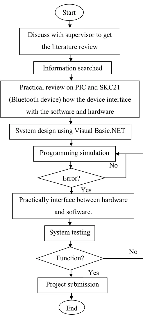
[image:24.612.213.459.91.633.2]1.6 Project Methodology
Figure1.0: Flow chart for project methodology Start
Discuss with supervisor to get the literature review
Information searched
Practical review on PIC and SKC21 (Bluetooth device) how the device interface
with the software and hardware
System design using Visual Basic.NET
Practically interface between hardware and software.
Error?
Programming simulation
System testing
No
Yes
Function? No
Project submission
End