International Journal of Innovative Technology and Exploring Engineering (IJITEE) ISSN: 2278-3075, Volume-8 Issue-7 May, 2019
Model Testing of Reinforced Soil Slope under
Surcharge Loading With Adaptable Confronting
Sandeep Kumar, Amanpreet Tangri, Abhishek Singh Rana
Abstract
:
Soil nailing is a mechanism used to strengthen and the existing soil. A number of bars are installed into a slope during the top-down excavation. The excavation support is an effective and economical way to build a retention wall to support hilltop, bridge abutments and highways. This process is effective on uneven soils, broken rock, shale and hard surface conditions. In this research, a physical model is prepared that comprises of pressure gauge, Acrylic sheet, flex sensor, multimeter and four steel bars. The experiments are conducted on four different materials named as Hexagon Geonet, tuflex geonet, hexagonal drainage geonet, and Biaxial Geogrid..From the experiment it is observed that Biaxial Geogrid can bear maximum stress of 78 Kg/cm2. Also the experiment is performed with flexible facing and rigid facing and concluded that rigid facing perform well with a maximum stress of 98 Kg/cm2.Index Terms:Soil nailing, Flexible facing, rigid facing
I. INTRODUCTION
Soil nailing is a construction process utilized to enhance the strength of ground that ensures the safety of new or existing land slopes. The reinforcing action of the ground is increased via the nail insertion process which in returns increases tensile force in soil nail [1]. The main part of the resistance becomes from the enlargement of axial force, which is a tension force. Specifically, cutting and bending may contribute little to the resistance [2].
In the late 1960s, soil nailing technique was applied to the construction project in Mexico City. Soil nailing developed from the novel Austrian tunnelling system, used for underground digging in rock[3]. Since the early 1960s, this concept of combining passive steel and shotcrete has also been applied to the stabilization of rock slopes. It has gained popularity in Europe since 1970 given by Shaw-Shong, L.(2005)[4]. In order to understand the effects of soil properties and different experimental conditions on the interaction mechanism, direct shear tests (Jewell, 1990)[5] and pull tests (Chang and Milligan, 1996)[6] were carried out and the results were reported appropriately. Various researchers have also studied the effects of different parameters such as nail roughness, stiffness, flexibility, nail dip, soil properties such as internal friction angle and expansion. The application of the finite element method (Su et al., 2006)[7] has been proposed for estimating the maximum shear stress generation at the soil nail interface and understanding the concept of expansion and stress relief
Revised Manuscript Received on May 5, 2019
Sandeep Kumar, M.E,Student, Department, Civil Engineering Chandigarh University, Chandigarh, India.
Er. Amanpreet Tangri, Assistant Professor, Civil Engineering department, Chandigarh University, Chandigarh, India.
after drilling. In order to evaluate the maximum stress produced by the interface against the soil nail in the passive zone [8]. Soil nailing walls are a widely used technique for keeping vertical cuts on any slope. A large part of the cost of landing is related to the construction of the reinforced concrete surface [9]. Soil facing is mainly categorized into two types namely; flexible and rigid. In this study, the potential for the use of flexible facial design for the nailed walls of the soil to replace the reinforced concrete surface was studied [10]. This approach provides ecological benefits for the features that allow the growth of greenery of plantation11].
A. Ideal conditions of soil nailing
While designing flexible facing the ideal conditions must be taken into considerations like as Remaining residues, scattered rock that does not have an unfavorable direction [12]. The surface of the soil has been very effective for relocation of temporary drilling and stabilization of unstable slopes[13].
B. Uses of soil nailing
i. Soil nailing mainly used for Protection and Preservation Historical Buildings.
ii. To repair a retaining wall supporting the base of the dam at the historic hydroelectric power plant
iii. To stabilize and improve the slope of the Castle hill
iv. Roadway cuts
v.
Road widening under existing bridge abutments[14]
c. Design Criteria
The Designer shall consult with the Regional Geotechnical Engineer (RGE) as early as possible in the design phase to ensure adequate subsurface explorations are progressed to verify the feasibility of installing the soil nail wall system [15]. When considering the use of a soil nail wall system, it is recommended that the Designer contact the RGE for the determination of the appropriate subsurface exploration locations and subsequent analysis of the soil for its suitability for soil nailing [16]. The anticipated construction sequencing with regard to the work zone traffic control to determine if additional subsurface explorations are required [17].
II. INDEX PROPERTIES OF SOIL
Initially, the soil was collected from the campus of Chandigarh University and then tested on the basis of the code properties (IS2720-1983). Features such as moisture content, specific weight,
Proctor test were analyzed. Prices are given in Table I.
Table I Soil’s index Features
Features Values
Water Content (%) 11
Specific Gravity 2.564
Liquid Limit (%) 17.59
Plastic Limit (%) 10
Plastic Index 7.59
Maximum Dry Density (MDD) (g/cc)
1.985
Optimum Moisture Content (OMC) (%)
7.3
Unconfined Compressive Strength
Kg/cm2
0.118
III. PHYSICAL MODEL
[image:2.595.40.295.91.275.2]The model face is of 60 cm length, 40 cm wide and 50 cm high, with a slope angle of 60 as depicted in figure 1. The model is planned as per the code-US –FHWA-NHI-14-007-FHWA GEC 007 February 2015.
Figure 1 Physical Model
The soil is well graded collected from Chandigarh main campus having different characteristics such as: mean particle diameter 0.19mm, non –uniformity coefficient measured by using following formula:
, which is equal to 5.6, when and are 0.56 and 0.1 respectively.
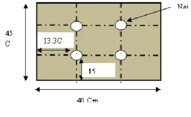
The soil is prepared in homogeneous layers having distance of 15 cm with , The nail spacing can be demonstrated in figure 2. The soil nail spacing is decided as per the code-US –FHWA-NHI-14-007-FHWA GEC 007 February 2015. The length is vary from 0.7h to 1 H, in our model H=45 cm as shown in figure 2. The nail of 45 cm length has been considered during the experiment and placed in soil with horizontal and vertical spacing of 13.3 cm measured from center to center and 15 cm spacing respectively as shown in fig. 2.
Figure 2 Soil nails spacing
There are four numbers of bars that are placed in horizontal as well as in vertical fashion with steel bar diameter of 10 mm. A number of components are used to design a physical model, the detail description is provided below:
i. Pressure hydraulic bottle jack
It is a mechanical tool that can be used as a lifting device to raise heavy loads or apply large forces. A mechanical jack uses a screw thread to lift heavy equipment. A hydraulic jack uses hydraulic power. Hydraulic jacks use an incompressible liquid that is forced into the cylinder through the pump plunger. Oil is used because of its self-lubricating properties and stability. The bottle jack is similar to the bottle with a cylindrical body and neck.
ii. Pressure gauge
Pressure measurement is an analysis of the force applied by fluid on the soil surface. The pressure is usually deliberated in units of force/surface area
iii. PERSPEX SHEET (Acrylic Sheet)
Acrylic sheet has a moldable material, is lightweight, has high impact resistance, and has excellent optical transparency, and can be widely used in various fields preferably in building commercial and structure glazing. In this research, Acrylic sheet of 8mm is used.
i. Steel Bar
In this research stainless steel bar in round shape are used. The benefit of using round in shape is that it is corrosion free and withstands the onslaughts of acid. Four number of steel bar with 45 cm of length and 10mm of diameter are used.
ii. Flex sensor
Flexible sensor is fit into the nails to sense the bearing load applied by pressure gauge. A copper wire is attached to it and extended towards the electrical switch.
iii. Miscellaneous
[image:2.595.55.284.372.480.2]International Journal of Innovative Technology and Exploring Engineering (IJITEE) ISSN: 2278-3075, Volume-8 Issue-7 May, 2019
IV. RESULT AND ANALYSIS
[image:3.595.327.527.54.194.2]The experiments are conducted on four different materials named as Hexagon Geonet, the tuflex geonet, hexagonal drainage geonet, and Biaxial Geogrid. The strain is measured by using a multimeter connected through main board comprises of four different switches.
Table II Testing using Hexagon Geonet of 6mm
Stress(Kg/cm 2
)
Nail-1(Strai
n)
Nail-2(Strai
n)
Nail-3(Strai
n)
Nail-4(Strai
n)
5 0.008 0.167 0.033 0.025
10 0.016 0.224 0.050 0.045
15 0.024 0.291 0.065 0.131
20 0.025 0.297 0.124 0.170
30 0.167 0.499 0.432 0.463
Hexagon Geonet is used as a testing material, the material composed of different properties such as Retaining Wall. The stress is varied from 5 Kg/cm2 to 30 Kg/cm2 and the strain has been measured using multimeter.
Figure 3 Stress vs Strain for Hexagon Geonet
Copper wire is connected to flex sensors installed in the nails, the copper wire is extended and connected to the switch board that comprises of four number of switched. Each switch is connected to an individual nail. Multimeter is connected to the individual switch, and hence measured the resistance. The, strain if individual nail is determined by putting remaining switched off. The formula used to calculate strain is defined below:
[image:3.595.49.289.159.278.2]
Here represents the gauge factor, its value lies between 2 to 2.5 and for 200k Ω, the value of gauge factor is 2.1.
Figure 4 Stress vs Strain for Tuflex Geonet
[image:3.595.309.546.326.444.2]From the graph depicted in figure 3 it is clear that as the stress increases strain also increases on nail-1, nail-2, nail-3 and nail-4 respectively. As the stress reaches upto 30 Kg/cm2, the crack appears on soil. Therefore this is maximum value of stress that a Hexagon Geonet material of 6mm can tolerate.
Table III Testing using Tuflex Geonet of 5 mm
Stress(Kg/cm 2
)
Nail-1(Strai
n)
Nail-2(Strai
n)
Nail-3(Strai
n)
Nail-4(Strai
n)
5 0.175 0.017 0.018 0.004
10 0.185 0.019 0.026 0.009
15 0.216 0.031 0.043 0.014
20 0.375 0.033 0.084 0.031
50 0.408 0.107 0.091 0.236
It is most commonly used Geonet product that is easy available in the market. The values of stress and strain measured with this material are listed in table III. The graphical representation is shown in fig. 4. X-axis and y-axis represents the Strain and Stress respectively. From the graph, it is clear that as the load applied on soil nails increases strain also increases and become maximum at 50 Kg/ cm2. The maximum value of strain is observed at nail-1, which is equal to 0.408.
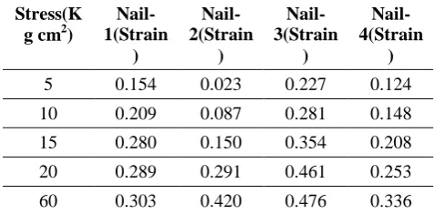
Table 4 Testing using Hexagonal Drainage Geonet of 6 mm
Stress(K g cm2)
Nail-1(Strain
)
Nail-2(Strain
)
Nail-3(Strain
)
Nail-4(Strain
)
5 0.154 0.023 0.227 0.124
10 0.209 0.087 0.281 0.148
15 0.280 0.150 0.354 0.208
20 0.289 0.291 0.461 0.253
60 0.303 0.420 0.476 0.336
Hexagonal Drainage Geonet is also applied and tested in terms of stress and strain. This material is mostly used in building construction for
[image:3.595.58.285.338.477.2] [image:3.595.307.546.598.715.2]strain are illustrated in table III.
[image:4.595.54.263.74.226.2][image:4.595.311.539.149.431.2]
Figure 5 Stress vs Strain of Hexagonal Drainage Geonet
Figure 6 Stress vs Strain of Biaxial Geogrid
Fig.5 represents the stress and strain values analyzed during the experiment for material Hexagonal Drainage Geonet. The cracks in the soil appear after 60 Kg/cm2. The maximum value of strain observered at 60 Kg/cm2 is about 0.476 at nail-3.
Table IV Testing using Biaxial Geogrid of 6 mm
Stress(Kg/c m2)
Nail-1(Strai n)
Nail-2(Strai n)
Nail-3(Strai n)
Nail-4(Strai n)
5 0.264 0.040 0.091 0.268
10 0.384 0.071 0.370 0.327
15 0.469 0.085 0.558 0.406
20 0.511 0.132 0.672 0.424
78 0.927 0.317 0.817 0.725
The forth material used for the testing is the Biaxial Geogrid of 6mm. It is a combined double-sided geogrid made of high quality polypropylene resin the test results are shown in table 4 with the graphical representation in Fig. 6, which indicates the stress and strain measured for four nails with different colors. From the figure it is clear that this is the strongest material found above other three materials and can tolerate load upto 78 Kg/cm2 with a maximum strain of 0.927.
V. COMPARISON BETWEEN NATURAL SOIL SLOPE
WITHOUT FACING,RIGID AND FLEXIBLE FACING
In this section, the comparison between rigid facing and flexible facing with and without material is discussed. The test values obtained after applying various load on flexible facing without material and rigid facing are listed in table V and table VI respectively.
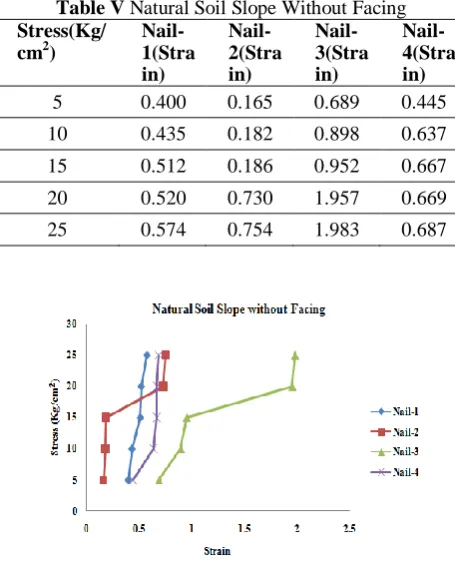
Table V Natural Soil Slope Without Facing Stress(Kg/
cm2)
Nail-1(Stra in)
Nail-2(Stra in)
Nail-3(Stra in)
Nail-4(Stra in)
5 0.400 0.165 0.689 0.445
10 0.435 0.182 0.898 0.637
15 0.512 0.186 0.952 0.667
20 0.520 0.730 1.957 0.669
[image:4.595.309.545.159.275.2]25 0.574 0.754 1.983 0.687
Figure 7 Stress vs Strain for natural soil without facing
Figure 8 Stress vs Strain with Rigid Material
Fig. 7, represents the stress versus strain graph without material. X-Axis and Y-axis represents the strain and stress respectively. The maximum stress measured for natural soil without facing model is about 25 Kg/cm2.
Table VI Rigid Facing Slope
Stress(Kg/ cm 2)
Nail-1(Stra in)
Nail-2(Stra in)
Nail-3(Stra in)
[image:4.595.53.259.268.419.2] [image:4.595.319.537.469.624.2]International Journal of Innovative Technology and Exploring Engineering (IJITEE) ISSN: 2278-3075, Volume-8 Issue-7 May, 2019
5 0.014 0.062 0.316 0.022
10 0.199 0.158 0.368 0.024
15 0.240 0.416 0.489 0.046
20 0.316 0.491 0.556 0.123
35 0.420 0.852 0.658 0.555
98 0.623 1.960 0.795 0.835
[image:5.595.67.270.229.378.2]The values measured with rigid facing and without flexible facing are listed in table 5 and table 6 respectively. The test experienced for rigid facing is depicted in fig. 8. For rigid facing the maximum stress of about 98Kg/cm2 is measured with a strain of 1.460 at nail-2.
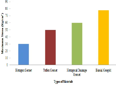
[image:5.595.53.259.409.569.2]Figure 9 Comparison between different materials
Figure 10 Comparison between different Types of Facing
It is clear that material Biaxial Geogrid perform better compared to remaining three materials with a maximum stress of 78 Kg/cm2. To show the strength and efficiency of the material a comparative analysis has been performed and the graph is plotted between without material, flexible facing and rigid facing respectively as shown in figure 10. From the graph it is clear that rigid facing perform well and can tolerate stress of about 98 Kg/cm2.
VI. CONCLUSION
It can be concluded that the present study will lead to an increase in the soil slopes load handling and slope stability. It has been analyzed that due to the lack of available data on structures the maximum load tolerated with flexible and
construction technique that even reflects cost-effective and low environmental impact. From the experimental it has been concluded that rigid facing perform well compared to flexible facing.
REFERENCES
1. Sharma, M., Samanta, M., & Sarkar, S. (2019). Soil nailing: an effective slope stabilization technique. In Landslides: Theory, Practice and Modelling (pp. 173-199). Springer, Cham.
2. Bhuiyan, M. Z. I., Wang, S., Sloan, S. W., Sheng, D., & Ming, L. K. (2018). Gravity Grouting and Its Future Alternative for Soil Reinforcement Systems. In Proceedings of China-Europe Conference on Geotechnical Engineering (pp. 898-901). Springer, Cham.
3. Rawat, P., & Chatterjee, K. (2018). Seismic stability analysis of soil slopes using soil nails. Geotechnical earthquake engineering and soil dynamics V: Slope Stability and Landslides, Laboratory Testing, and In Situ Testing, Geotechnical Special Publication, (293), 79-87.
4. Shaw-Shong, L. (2005). Soil nailing for slope strengthening. Geotechnical Engineering, Gue & Partners Sdn Bhd, Kuala Lumpur, Malaysia, 30-31.
5. Jewell, R. A. (1991). P3/12 Review of theoretical models for soil nailing. In Performance of Reinforced Soil Structures: Proceedings of the International Reinforced Soil Conference Organized by the British Geotechnical Society and Held in Glasgow on 10-12 September 1990 (p. 265). Thomas Telford.
6. Milligan, G.W.E., Chang, K.T., and Morris, J.D. 1997. Pull-out resistance of soil nails in sand and clay. In Proceeding of the 3rd International Conference on Ground Improvement Geosystems, London, UK, 3–5 June 1997. Edited by M.C.R. Davies and F. Scholsser, Thomas Telford, New York. pp. 414–422. Google Scholar 7. Yin, J. H., & Su, L. J. (2006). An innovative laboratory box for testing
nail pull-out resistance in soil. Geotechnical Testing Journal, 29(6), 451-461.
8. Pei, H., Yin, J., Zhu, H., & Hong, C. (2012). Performance monitoring of a glass fiber-reinforced polymer bar soil nail during laboratory pullout test using FBG sensing technology. International Journal of Geomechanics, 13(4), 467-472.
9. Bhuiyan, M. Z. I., Wang, S., Sloan, S. W., Sheng, D., & Ming, L. K. (2018). Gravity Grouting and Its Future Alternative for Soil Reinforcement Systems. In Proceedings of China-Europe Conference on Geotechnical Engineering (pp. 898-901). Springer, Cham.
10. Yazdandoust, M. (2017). Experimental study on seismic response of soil-nailed walls with permanent facing. Soil Dynamics and Earthquake Engineering, 98, 101-119.
11. Sarkar, R., Kurar, R., Zangmo, S., Dema, U. G., Subba, S. J., & Sharma, D. K. (2017). Application of soil nailing for landslide mitigation in Bhutan: a case study at Sorchen Bypass. Electron J Geotech Eng, 22(13), 4963-4980.
12. Yuan, J., Lin, P., Huang, R., & Que, Y. (2019). Statistical evaluation and calibration of two methods for predicting nail loads of soil nail walls in China. Computers and Geotechnics, 108, 269-279.
13. Pei, H. F., Li, C., Zhu, H. H., & Wang, Y. J. (2013). Slope stability analysis based on measured strains along soil nails using FBG sensing technology. Mathematical Problems in Engineering, 2013.
14. Da Costa, A., & Sagaseta, C. (2010). Analysis of shallow instabilities in soil slopes reinforced with nailed steel wire meshes. Engineering Geology, 113(1-4), 53-61.
15. Yuan, J. X., Yang, Y., Tham, L. G., Lee, P. K. K., & Tsui, Y. (2003). New approach to limit equilibrium and reliability analysis of soil nailed walls. International Journal of Geomechanics, 3(2), 145-151.
16. Alston, C., & Crowe, R. E. (1992). Design and construction of two low retaining wall systems restrained by soil nail anchors. Transportation research record, (1414).