Digital simulation of physical processes in
vehicles engine power units
aSergey Hoodorozhkov1, Andrey Krasilnikov1*, Evgeney Zakhlebayev1
1 Peter the Great St. Petersburg Polytechnic University, 195251 Polytechnicheskaya st. 29, Russian Federation
Abstract. This article studies the issues of digital simulation of physical operating processes in vehicles transmission. Simulation of dynamic processes is carried out in power transmissions at the design stage. The procedure for using the digital packages such as MATLab – Simulink and Simscape was considered for the numerical simulation of dynamic processes in mechanical systems based on the example of the theoretical calculation of 744 tractor transmission dynamics. A digital model of K-744 tractor transmission is constructed, its calculation scheme is given, the initial characteristics are determined. A digital model of the tractor engine was created by means of the Simulink package. A nature of change in tractor engine torqueis determined by it. The calculated analysis of normal transmission frequencies is performed. Forced torsional vibrations are calculated in the tractor change gearbox generated by the vehicle engine operation. The conditions of resonance in the transmission are analyzed. The unfavorable modes of joint operation of the engine and the gearbox are determined for K-744 tractor.
1 Introduction
pressure in cylinders and from engine inertia forces. The frequency diagram is made and resonant modes are determined [1, 2]. In this case, as a result of the multimass system simplification, the calculations accuracy decreases.
2 Purpose
The purpose of this study was to develop the algorithm for numerical study of dynamic processes in vehicles transmissions using modern digital software packages. The solution of this task will allow providing the adoption of justified effective technical solutions at development of new models of equipment, and reducing a time of their creation.
3 Problem solution mode
For digital simulation of dynamic processes in vehicles transmission, it is proposed to use modern software tools for engineering calculations, in particular, the applications of MATLab package – Simulink and Simscape [3, 4]. This method provides for substantial simplification of dynamic calculations for power transmissions. The MATLab packages –
Simulink and Simscape provide fundamental blocks that can be used to create models of physical components – such as an internal combustion engine, friction clutch, gear reduction unit, flexible shafts, damping devices and other components of the power transmission. The Simscape automatically derives the differential equations featuring system behavior from a model which form is close to the kinematic scheme, [5, 6].
This paper, as an example of the simulation of torsional vibrations in a perspective automated K-744 tractor gearbox, considers the algorithm and results of this mathematical application usage.
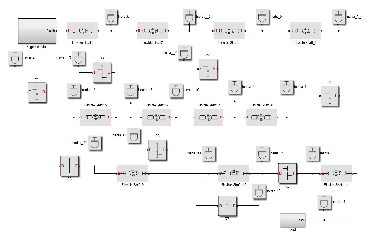
Based on the known kinematic, inertial-elastic and damping parameters of the gearbox, a Simscape model is developed (Fig. 1) to simulate dynamic processes, in particular torsion vibrations under the action of the engine torque. As an example, the Simscape-model of the gearbox with the engine is displayed in the following state – the first gear, the first range, the bench mode of output shaft load.
The figure shows the gearbox shafts in the form of typical library blocks "Flexible Shaft_1 ... 11" describing the elastic-damping and inertia features by the sections broken at
the connection points of blocks "Inertia_5 ... 17” featuring a response time of the driven and
drive masses of friction clutches, and gear wheels fixed on shafts. The gearbox properties are described by means of blocks "Simple Gear": R1…R8.
pressure in cylinders and from engine inertia forces. The frequency diagram is made and resonant modes are determined [1, 2]. In this case, as a result of the multimass system simplification, the calculations accuracy decreases.
2 Purpose
The purpose of this study was to develop the algorithm for numerical study of dynamic processes in vehicles transmissions using modern digital software packages. The solution of this task will allow providing the adoption of justified effective technical solutions at development of new models of equipment, and reducing a time of their creation.
3 Problem solution mode
For digital simulation of dynamic processes in vehicles transmission, it is proposed to use modern software tools for engineering calculations, in particular, the applications of MATLab package – Simulink and Simscape [3, 4]. This method provides for substantial simplification of dynamic calculations for power transmissions. The MATLab packages –
Simulink and Simscape provide fundamental blocks that can be used to create models of physical components – such as an internal combustion engine, friction clutch, gear reduction unit, flexible shafts, damping devices and other components of the power transmission. The Simscape automatically derives the differential equations featuring system behavior from a model which form is close to the kinematic scheme, [5, 6].
This paper, as an example of the simulation of torsional vibrations in a perspective automated K-744 tractor gearbox, considers the algorithm and results of this mathematical application usage.
Based on the known kinematic, inertial-elastic and damping parameters of the gearbox, a Simscape model is developed (Fig. 1) to simulate dynamic processes, in particular torsion vibrations under the action of the engine torque. As an example, the Simscape-model of the gearbox with the engine is displayed in the following state – the first gear, the first range, the bench mode of output shaft load.
The figure shows the gearbox shafts in the form of typical library blocks "Flexible Shaft_1 ... 11" describing the elastic-damping and inertia features by the sections broken at
the connection points of blocks "Inertia_5 ... 17” featuring a response time of the driven and
drive masses of friction clutches, and gear wheels fixed on shafts. The gearbox properties are described by means of blocks "Simple Gear": R1…R8.
[image:3.482.51.447.62.300.2]When simulating, real values are given for the inertia moments of gearbox rotating masses, values of torsion stiffness of shaft sections, gear ratios of gear pairs.
Fig. 1. Simscape-model of К-744 tractor gearbox (1st gear, 1st mode).
К-744 tractor gearbox is mated to engine ЯМЗ-5362 [7]. In the model shown in Fig. 1 the engine block with the gearbox is represented by the subsystem "Engine + Clutch", which is a 6-cylinder internal combustion engine with a reciprocating duty cycle. The reciprocating internal combustion engine model calculates the current torque transmitted by the engine crankshaft, and allows simulating transmission vibration. As an example, the total engine torques for the duty cycle at the external speed characteristic at revolutions neng.equal to 2000 rpm are shown in Fig. 2. Torqueses are determined by the results of
thermal, kinematic and dynamic calculations of the engine.
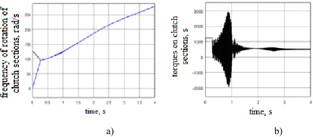
[image:3.482.62.321.476.573.2]The results of simulating the torsion vibrations in the tractor transmission gearbox at the 1st gear and the first mode in the bench loading conditions are shown in Fig. 3. The braking mode of the gearbox output shaft and the rate of the first transmission clutch actuation are adopted to simulate the start-up and acceleration mode with equalizing the speeds of the drive and driven masses of friction clutch (see Fig. 3, a).
The curves of torque on the input "Flexible Shaft_1" and output "Flexible Shaft_4" sections of the input shaft (Fig. 1) when the engine rpm corresponding to Fig. 3, a are shown in Fig. 3, b, as an example.
[image:4.482.63.380.171.310.2]a) b)
Fig. 3. A speed of drive ω1 and driven ω2 masses of the friction clutch (a) and torques at the shaft
sections "Flexible Shaft_1…4" (b).
It follows from the graphs that, at the end of the transient process associated with the equalization of speed of drive and driven masses of the friction clutch, the stationary torque components on the shafts correspond to resistance moment at the gearbox output shaft taking into account the reducing steps. In this case, at t=0.9(it corresponds to the engine speed ω = 115 rad/s, see Fig. 3a), a resonance of torsional vibrations is observed at the input and intermediate shafts – Fig. 3b caused by coincidence of free and forced frequencies of gearbox inertia-elastic links. At t=2.7s (corresponding to the engine speed ω = 217 rad/s), the second resonance is observed on the same shafts – Fig. 3, b.
To test the conditions for the existence of resonance effects, it is necessary to determine the spectra of gearbox natural oscillations and forced oscillations due to the action of the engine torque. In the first case, it is advisable to use the Linear Time-Invariant models (LTI) in the MATLab programming environment using a logarithmic amplitude-frequency response (Bode diagram).
The results of simulating the torsion vibrations in the tractor transmission gearbox at the 1st gear and the first mode in the bench loading conditions are shown in Fig. 3. The braking mode of the gearbox output shaft and the rate of the first transmission clutch actuation are adopted to simulate the start-up and acceleration mode with equalizing the speeds of the drive and driven masses of friction clutch (see Fig. 3, a).
The curves of torque on the input "Flexible Shaft_1" and output "Flexible Shaft_4" sections of the input shaft (Fig. 1) when the engine rpm corresponding to Fig. 3, a are shown in Fig. 3, b, as an example.
a) b)
Fig. 3. A speed of drive ω1 and driven ω2 masses of the friction clutch (a) and torques at the shaft
sections "Flexible Shaft_1…4" (b).
It follows from the graphs that, at the end of the transient process associated with the equalization of speed of drive and driven masses of the friction clutch, the stationary torque components on the shafts correspond to resistance moment at the gearbox output shaft taking into account the reducing steps. In this case, at t=0.9(it corresponds to the engine speed ω = 115 rad/s, see Fig. 3a), a resonance of torsional vibrations is observed at the input and intermediate shafts – Fig. 3b caused by coincidence of free and forced frequencies of gearbox inertia-elastic links. At t=2.7s (corresponding to the engine speed ω = 217 rad/s), the second resonance is observed on the same shafts – Fig. 3, b.
To test the conditions for the existence of resonance effects, it is necessary to determine the spectra of gearbox natural oscillations and forced oscillations due to the action of the engine torque. In the first case, it is advisable to use the Linear Time-Invariant models (LTI) in the MATLab programming environment using a logarithmic amplitude-frequency response (Bode diagram).
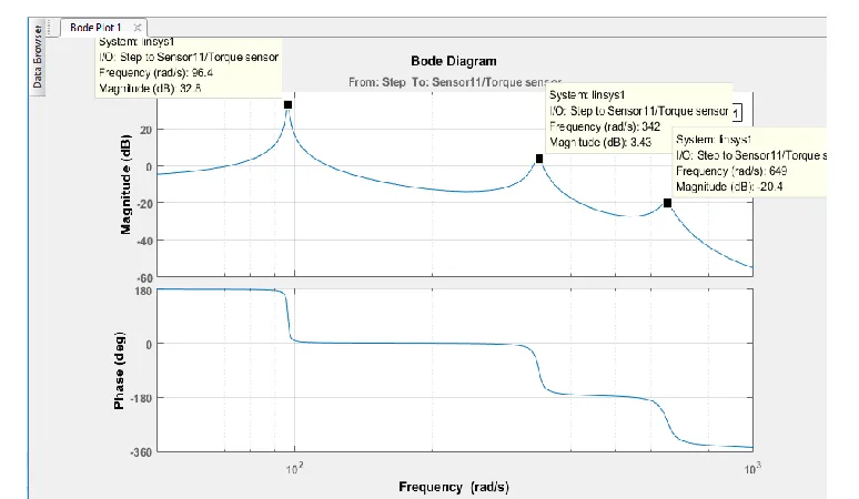
[image:5.482.49.436.61.286.2]When constructing the Bode diagram, input and output points (Loop Input, Open-Loop Output) shall be set on the input and output shafts of the gearbox of the Simscape model, and start the "Analysis-Control Design-Linear Analysis" procedure. The results of Bode diagram construction is given in Fig. 4.
Fig. 4. The Bode diagram of the gearbox (Simscape-model, 1st gear)
Maximum resonance amplitudes on the graph correspond to free frequencies of the system – 96.4, 342 and 649 rad/s. Other free frequencies are insignificant (by amplitude).
For frequency analysis of external disturbance of the gearbox input shaft caused by an engine torque, it is advisable to use the fast Fourier transform:
sum
A fft M (1)
where: A – frequency-domain representation of engine torque;
Msum– summary engine torque in terms of crank angle within an interval of 0 to 720 deg. (see Fig. 3), kN·m;
fft– standard function of the fast Fourier transform.
Torque spectrum amplitudes are determined using the formula
2
2l l l
M s Re A Im A (2)
where: Re A l – real part of the spectrum;
l
Im A – imaginary part of the spectrum; l– number of harmonics for torque synthesis. Synthesis harmonics spectrum phases
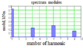
The results of the frequency analysis of engine torque at the speed neng., 2000 rpm are
[image:6.482.159.322.101.196.2]given in Fig. 5.
Fig. 5. Engine torque spectrum modules at speeds neng.=2000 rpm at full-load curve
Inverse Fourier transform domain into torque recovery curves is represented as synthesized expression
c l··cos · ·
c l·
lM t
M l t Q (5)Torque frequency analysis suggests that, in addition to the constant component with zero frequency М0, the frequency spectrum with maximum amplitudes includes 3rd, 6th
and 9th order harmonics. With increasing crank speed from 1200 to 2300 rpm, the 3rd harmonics amplitude М3·сdecreases approximately 6 times (from 0.66 to 0.099 kN·m), the
remaining components of the amplitude spectrum remain practically unchanged.
It is possible to determine engine speeds based on the known frequencies of free torsional oscillations and engine torque spectrum, which will force torsion resonance frequency in the tractor transmission gearbox.
The diagram for frequencies of free torsional vibrations of the tractor transmission gearbox: ωс1=96.4 rad/s, ωс2=342 rad/s, ωс3=649 rad/s allows to determine resonance frequencies ωrof engine rotation: on basic harmonics n _eng: ωr_1 =96 rad/s, on overtone of
3rd order external frequency ωr_2=115 rad/s, and ωr_3 =217 rad/s.
The above data confirm the adequacy of the results obtained during computer simulation of the Simscape model: the presence of resonant effects at torsional vibrations of shafts in the gearbox on the overtone of the 3rd order engine external frequency. Engine fundamental harmonic resonance is not recorded, since the initial speed of the gearbox input shaft upon completion of friction clutch slipping in case of simulation of the process for starting and acceleration in the 1st gear and the 1st mode is over 96 rad/s.
4 Conclusions
As a result of theoretical study, the following has been defined:
1. Application of the engineering environment MATHWORKS SIMSCAPE in the digital simulation of dynamic processes in vehicles transmissions provides for significant reduction in calculations volume and complexity.
2. The MATHWORKS SIMSCAPE package includes the library of necessary model blocks to simulate transmission elements including the internal combustion engine with setting the required characteristics.
The results of the frequency analysis of engine torque at the speed neng., 2000 rpm are
given in Fig. 5.
Fig. 5. Engine torque spectrum modules at speeds neng.=2000 rpm at full-load curve
Inverse Fourier transform domain into torque recovery curves is represented as synthesized expression
c l··cos · ·
c l·
lM t
M l t Q (5)Torque frequency analysis suggests that, in addition to the constant component with zero frequency М0, the frequency spectrum with maximum amplitudes includes 3rd, 6th
and 9th order harmonics. With increasing crank speed from 1200 to 2300 rpm, the 3rd harmonics amplitude М3·сdecreases approximately 6 times (from 0.66 to 0.099 kN·m), the
remaining components of the amplitude spectrum remain practically unchanged.
It is possible to determine engine speeds based on the known frequencies of free torsional oscillations and engine torque spectrum, which will force torsion resonance frequency in the tractor transmission gearbox.
The diagram for frequencies of free torsional vibrations of the tractor transmission gearbox: ωс1=96.4 rad/s, ωс2=342 rad/s, ωс3=649 rad/s allows to determine resonance frequencies ωrof engine rotation: on basic harmonics n _eng: ωr_1 =96 rad/s, on overtone of
3rd order external frequency ωr_2=115 rad/s, and ωr_3 =217 rad/s.
The above data confirm the adequacy of the results obtained during computer simulation of the Simscape model: the presence of resonant effects at torsional vibrations of shafts in the gearbox on the overtone of the 3rd order engine external frequency. Engine fundamental harmonic resonance is not recorded, since the initial speed of the gearbox input shaft upon completion of friction clutch slipping in case of simulation of the process for starting and acceleration in the 1st gear and the 1st mode is over 96 rad/s.
4 Conclusions
including directly in the simulation process, as well as large data arrays recording and storing.
The obtained results allow effective using the presented algorithms during virtual simulation of dynamic systems of vehicle transmissions, particularly during calculation of torsional vibrations in transmission gearboxes.
References
1. S. Timoshenko, D. H. Young, W. Weaver Jr., Vibration problems in engineering (John Wiley & SONS, Inc., New York, 1974)
2. G.S. Maslov, Calculations of shafts (Engineering, Moscow, 1980)
3. Simscape™ User’s Guide. Copyright 2007, by The Math Works, Inc. [online], Availa-ble at: https://www.mathworks.com/help/physmod/simscape/ (2013)
4. Using SIMULINK. Copyright 1990, by The Math Works, Inc. [online], Available at: http://aer.ual.es/docencia_es/sr/archivos/simulink.pdf (1996)
5. S. I. Hoodorozhkov, Theory and automated control systems. Simulink Transport sys-tems ACS analysis and synthesis (Publishing House of Polytechnic University, St. Pe-tersburg, 2014)
6. S. Hoodorozhkov, E. Zakhlebaev, Scientific and technical statements of SPbSPU, 231
(2015)