ISSN :2394-2231
http://www.ijctjournal.org
Page 6
RECYCLING ORGANIC WASTE
1
Ms. Akila .S,
2Ms. Siva sankari A.
1M.Phil Research Scholar, Department of Computer Science DKM College for Women (Autonomous), Vellore, TamilNadu, India.
2 HOD, Department of Computer Science DKM College for Women (Autonomous), Vellore, TamilNadu, India.
---
************************
---Abstract:
Solid waste management is a big challenge in urban areas for most of the countries throughout the world. There are many technologies are used for waste collection as well as for well managed recycling. The concurrent effects of a fast national growth rate, of a large and dense residential area and a pressing demand for urban environmental protection create a challenging framework for waste management.In this project humans and vehicles were used to do that work and here we are using automatic technique to detect garbage level in Garbage Can. For that, ID number is given to each can. Also as soon as the Garbage Can is full / over flowing then a Message is sent to the server from where all the garbage collection vehicles are allotted.The main urban wastages are household food waste, agricultural waste, human and animal waste. The waste component of landfill is broken down by micro-organisms to form a liquid ‘leachate’ which contains bacteria, rotting matter and maybe chemical contaminants from the landfill.
Keywords
—Solid waste management, environmental protection, micro-organisms.
---
************************
---I. INTRODUCTION
Solid waste management is a big challenge in urban areas for most of the countries throughout the world. An efficient waste management is a pre requisition for maintain a safe and green environment as there are increasing all kinds of waste disposal. There are many technologies are used for waste collection as well as for well managed recycling. The Information gathering is big and cumbersome. The concurrent effects of a fast national growth rate, of a large and dense residential area and a pressing demand for urban environmental protection create a challenging framework for waste management. The complexity of context and procedures is indeed a primary concern of local municipal authorities due to problems related to the collection, transportation and processing of residential solid waste today the garbage collection is manual which takes a lot of efforts and is time consuming.
In this paper humans and vehicles were used to do that work and here we are using automatic technique to detect garbage level in Garbage Can. For that, ID number is given to each can. Also as soon as the Garbage Can is full / over flowing then a Message is sent to the server from where all the garbage collection vehicles are allotted.
1.1 ORGANIC WASTE- TYPES, SOURCES AND USES As mentioned earlier, there a number of types of organic waste which are commonly discarded. Below we will look at the types and sources of organic waste and some examples of common uses for this waste.
1.2 DOMESTIC AND HOUSEHOLD WASTE
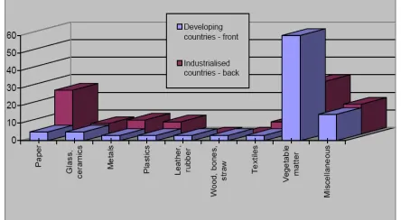
This type of waste is usually made up of food scraps, either cooked or uncooked, and garden waste such as grass cuttings or trimmings from bushes and hedges. Domestic kitchen waste is often mixed with non-organic materials such as plastic packaging, which cannot be composted. It is beneficial if this type of waste can be separated at source – this makes recycling of both types of waste far easier. Domestic or household waste is usually produced in relatively small quantities. In developing countries, there is a much higher organic content in domestic waste.
Figure 1.1: Composition of municipal waste in a typical developing and industrialized country
ISSN :2394-2231
http://www.ijctjournal.org
Page 7 for use in conjunction with small-scale enterprise is good
(see box 2).
1.4 ANIMAL AND HUMAN WASTE
It is worth mentioning at the start of this section that there are serious health risks involved with handling sewage. Raw sewage contains bacteria and pathogens that cause serious illness and disease. It should be stressed that health and safety procedures should be followed when dealing with sewage and that people involved with its handling should have a clear understanding of the health risks involved. Raw sewage should never be applied to crops which are for consumption by humans or animals.
1.5 COMPOSTING
Composting is simply the method of breaking down organic materials in a large container or heap. The decomposition occurs because of the action of naturally occurring micro-organisms such as bacteria and fungi. Small invertebrates, such as earthworms and millipedes, help to complete the process. Composting can convert organic waste into rich, dark colored compost, or humus, in a matter of a few weeks or months.
There is nothing mysterious or complicated about composting. Natural composting, or decomposition, occurs all the time in the natural world. Organic material, the remains of dead animals and plants, is broken down and consumed by micro-organisms and eaten by small invertebrates. Under controlled conditions, however, the process can be speeded up.
Composting has many benefits:
It provides a useful way of reclaiming nutrients from organic refuse
Saves valuable landfill space and possible contamination of land and water due to landfill ‘leachate’
Can be used as fertiliser on farmland or in the garden
Improves the condition of soils
1.6 FORMS OF DECOMPOSITION
ANEAROBIC
In anaerobic decomposition, the breakdown of the organic material is caused by bacteria and fungi that thrive in low or no-oxygen conditions. It is the type of decomposition that takes place in closed containers. This type of system is more complex and difficult to control and requires complex equipment for larger scale composting.
AEROBIC
In aerobic decomposition, bacteria and fungi which thrive in high oxygen conditions are responsible for the decomposition. This form of decomposition occurs in open heaps and containers that allow air to enter. With open heaps and more ventilated containers, compost can be formed in a matter of a few months, and even faster if the organic material is turned regularly. In heaps or bins
where aerobic decomposition is occurring, there should be no unpleasant odours.
1.7 SOME METHODS OF COMPOSTING
Composting systems can be opened or closed, that is the organic matter will either be placed in open piles or rows or in a closed container or reactor. The open system is rarely used in low-income countries due to its technical complexity, so we look at some of the open systems in use.
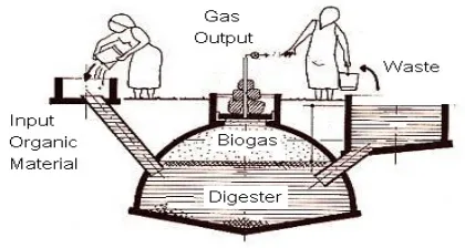
1.8 BIOGAS PRODUCTION
Biogas is produced by means of a process known as anaerobic digestion. It is a process whereby organic matter is broken down by microbiological activity and takes place in the absence of air (anaerobic means ‘in the absence of air’). It is a phenomenon that occurs naturally at the bottom of ponds and marshes and gives rise to ‘marsh gas’ or methane, which is a combustible gas. It also takes place naturally in landfill sites and contributes to harmful greenhouse gases.
The digestion of waste yields several benefits:
The production of methane for use as a fuel.
The waste is reduced to slurry which has a high nutrient content which makes an ideal fertiliser; in some cases this fertiliser is the main product from the digester and the biogas is merely a by-product.
During the digestion process pathogens in the manure are killed, which is a great benefit to environmental health.
Figure 1.2: A typical floating cover biogas digester
II COMPONENTS USED
2.1 Circuit Board
ISSN :2394-2231
http://www.ijctjournal.org
Page 8 new data and new understanding dictating the course of
the design. Since breadboard circuits exist only in the laboratory, no special consideration need be given to creating reliable or simple-to-manufacture circuits - the designer can focus exclusively on the circuit's behavior. 2.2 Connectors
The Digilab board uses several connectors for various purposes, but in general, they all communicate electronic information between the board and outside devices. By convention, connectors are given the reference designator "J__". Since connectors come in so many different sizes and shapes, they are usually shown on the PCB silk screen and on circuit schematics as just rectangular boxes. In general, connectors must be placed into the PCB in a particular orientation. Most often, the unique through-hole patterns associated with a given connector make it obvious how it must be inserted.
2.3 Output LEDS
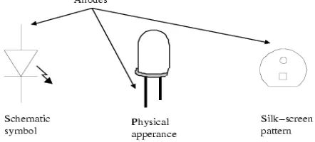
Circuits often require output devices to communicate their state to an user. Examples of electronic output devices include computer monitors, LCD alphanumeric panels (as on a calculator), small lamps or light-emitting diodes (LED's), etc. Outputs from the Digilab board consist of eight individual LED's and a four-digit LED display that can display the digits 0-9 in each digit position. As with diodes, LED's are two-terminal semiconductor devices that conduct current in only one direction (from the anode to the cathode).
Figure 2.1 Light-Emitting Diodes
2.4 Diodes
Diodes are constructed from the same type of silicon as transistors, but they are simpler devices that have only two terminals. Called the anode and cathode, the two ends of the diode are constructed of positively doped silicon (the anode) joined directly to negatively doped silicon (the cathode). This pn-junction exhibits the unique characteristic of allowing current to flow in only one direction (from the anode to the cathode).
2.5 Integrated Circuits
The terms chip and integrated circuit refer circuits using microscopic transistors that are all co-located on the same small piece of silicon. Chips have been designed to do all sorts of functions, from very simple and basic logical switching functions to highly complex processing functions.
Some chips contain just a handful of transistors, while others contain several million transistors. Some of the longest-surviving chips perform the most basic functions. These chips, denoted with the standard part numbers "74XXX", are simple small-scale integration devices that house small collections of logic circuits. For example, a chip known as a 7400 contains four individual NAND gates, with each input and output available at an external pin.
2.6 Capacitors
A capacitor is a two-terminal device that can store electric energy in the form of charged particles. You can think of a capacitor as a reservoir of charge that takes time to fill or empty. The voltage across a capacitor is proportional to the amount of charge it is storing - since it is not possible to instantaneously move charge to or from a capacitor, it is not possible to instantaneously change the voltage across a capacitor. It is this property that makes capacitors useful on the Digilab board.
Figure 2.2 Capacitor
2.7 Resitor Packs
If a circuit application requires many resistors of the same value, and if those resistors can be located close together on a PCB, then a resistor pack can be used instead of individual resistors. Resistors in a pack function identically to discrete resistors - they are just more economical to work with. Several different types of resistor packs are available.
Two of the more common types, and the types used on the Digilab board, are called "bussed" packs and "isolated" packs. All resistors in a bussed resistor pack have one lead connected to a common node, while all resistors in an isolated pack have independent nodes.
III SENSOR USED
ISSN :2394-2231
http://www.ijctjournal.org
Page 9 The LM35’s low output impedance, linear output, and
precise inherent calibration make interfacing to readout or control circuitry especially easy.
Typical Applications
3.2 Smoke Sensor
3.2.1 Ionization Detectors
Ionization detectors have an ionization chamber and a source of ionizing radiation. The source of ionizing radiation is a minute quantity of americium-241 (perhaps 1/5000th of a gram), which is a source of alpha particles (helium nuclei). The ionization chamber consists of two plates separated by about a centimeter. The battery applies a voltage to the plates, charging one plate positive and the other plate negative. Alpha particles constantly released by the americium knock electrons off of the atoms in the air, ionizing the oxygen and nitrogen atoms in the chamber.
3.2.2 Photoelectric Detectors
In one type of photoelectric device, smoke can block a light beam. In this case, the reduction in light reaching a photocell sets off the alarm. In the most common type of photoelectric unit, however, light is scattered by smoke particles onto a photocell, initiating an alarm. In this type of detector there is a T-shaped chamber with a light-emitting diode (LED) that shoots a beam of light across the horizontal bar of the T.
3.2.3 Best Method
Both ionization and photoelectric detectors are effective smoke sensors. Both types of smoke detectors must pass the same test to be certified as UL smoke detectors. Ionization detectors respond more quickly to flaming fires with smaller combustion particles; photoelectric detectors respond more quickly to smoldering fires. In either type of detector, steam or high humidity can lead to condensation on the circuit board and sensor, causing the alarm to sound.
Figure 3.1: Smoke sensor Config with OP Amp
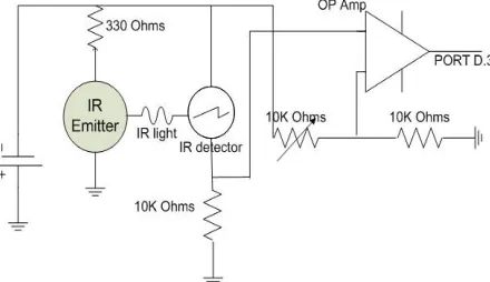
3.3 IR Sensor
Infrared (IR) light is electromagnetic radiation with a wavelength longer than that of visible light, measured from the nominal edge of visible red light at 0.74 micrometers (µm), and extending conventionally to 300 µm. These wavelengths correspond to a frequency range of approximately 1 to 400 THz, and include most of the thermal radiation emitted by objects near room temperature. Microscopically, IR light is typically emitted or absorbed by molecules when they change their rotational-vibration movements.
Infrared light is used in industrial, scientific, and medical applications. Night-vision devices using infrared illumination allow people or animals to be observed without the observer being detected. In astronomy, imaging at infrared wavelengths allows observation of objects obscured by interstellar dust. Infrared imaging cameras are used to detect heat loss in insulated systems, observe changing blood flow in the skin, and overheating of electrical apparatus.
Figure 3.2: Object detecting using IR light
IV COMMUNICATION USED
4.1 Radio Frequency (RF)
Radio frequency (RF) is a rate of oscillation in the range of about 3 kHz to 300 GHz, which corresponds to the frequency of radio waves, and the alternating currents which carry radio signals. RF usually refers to electrical rather than mechanical oscillations, although mechanical RF systems do exist.
ISSN :2394-2231
http://www.ijctjournal.org
Page 10 current or alternating current of lower frequencies. The
energy in an RF current can radiate off a conductor into space as electromagnetic waves (radio waves); this is the basis of radio technology. RF current does not penetrate deeply into electrical conductors but flows along their surfaces; this is known as the skin effect. For this reason, when the human body comes in contact with high power RF currents it can cause superficial but serious burns called RF burns.
4.2 RF Transmitting
The transmitting system consists of two tuned circuits such that the one containing the spark-gap is a persistent oscillator; the other, containing the aerial structure, is a free radiator maintained in oscillation by being coupled to the first. The transmitting system consists of two electrically coupled circuits, one of which, containing the air-gap, is a powerful but not persistent oscillator, being provided with a device for quenching the spark so soon as it has imparted sufficient energy to the other circuit containing the aerial structure, this second circuit then independently radiating the train of slightly damped waves at its own period.
4.3 RF Receiver
A radio receiver is an electronic circuit that receives its input from an antenna, uses electronic filters to separate a wanted radio signal from all other signals picked up by this antenna, amplifies it to a level suitable for further processing, and finally converts through demodulation and decoding the signal into a form usable for the consumer, such as sound, pictures, digital data, measurement values and navigational positions. Consumer audio and high fidelity audio receivers and AV receivers used by home stereo listeners and audio and home theatre system enthusiasts.
Communications receivers, used as a component of a radio communication link, characterized by high stability and reliability of performance. Simple crystal radio receivers (also known as a crystal set) which operate using the power received from radio waves. Satellite television receivers, used to receive television programming from communication satellites in geosynchronous orbit.
4.5 Decoder (HT12D)
The 212 decoders are a series of CMOS LSIs for remote control system applications. They are paired with Holtek’s 212series of encoders (refer to the encoder/decoder cross reference table). For proper operation, a pair of encoder/decoder with the same number of addresses and data format should be chosen. The decoders receive serial addresses and data from a programmed 212 series of encoders that are transmitted by a carrier using an RF or an IR transmission medium.
4.6 Encoder (12E)
The 212 encoders are a series of CMOS LSIs for remote control system applications. They are capable of encoding information which consists of N address bits and
12_N data bits. Each address/data input can be set to one of the two logic states. The programmed addresses/data are transmitted together with the header bits via an RF or an infrared transmission medium upon receipt of a trigger signal.
V PIC MICROCONTROLLER
PIC is a family of Harvard architecture microcontrollers made by Microchip Technology, derived from the PIC1650 originally developed by General Instrument's Microelectronics Division. The name PIC initially referred to "Peripheral Interface Controller".
PICs are popular with both industrial developers and hobbyists alike due to their low cost, wide availability, large user base, extensive collection of application notes, availability of low cost or free development tools, and serial programming (and re-programming with flash memory) capability.
5.1 High Performance RISC CPU
• Only 35-75 single-word instructions to learn • All single-cycle instructions except for program
branches, which are two-cycle • Operating speed: DC – 20 MHz clock input • DC – 200 ns instruction cycle
• Up to 8K x 14 words of Flash Program Memory, • Up to 368 x 8 bytes of Data Memory (RAM), • Up to 256 x 8 bytes of EEPROM Data Memory • Pin out compatible to other 28-pin or 40/44-pin
PIC16CXXX and PIC16FXXX microcontrollers
5.2 CMOS Technology
• Low-power, high-speed Flash/EEPROM technology
• Fully static design
• Wide operating voltage range (2.0V to 5.5V) • Commercial and Industrial temperature ranges • Low-power consumption
VI MEMORY ORGANIZATION
There are three memory blocks in each of the PIC16F87XA devices. The program memory and data memory have separate buses so that concurrent access can occur and is detailed in this section. The EEPROM data memory block is detailed in “Data EEPROM and Flash Program Memory”. Additional information on device memory may be found in the PICmicro® Mid-Range MCU Family Reference Manual (DS33023).
6.1 Program Memory Organization
ISSN :2394-2231
http://www.ijctjournal.org
Page 11 6.2 Data Memory Organization
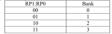
The data memory is partitioned into multiple banks which contain the General Purpose Registers and the Special Function Registers. Bits RP1 (Status<6>) and RP0 (Status<5>) are the bank select bits.
RP1:RP0 Bank
00 0
01 1
10 2
11 3
6.3 Data EEPROM and Flash Program Memory
The data EEPROM and Flash program memory is readable and writable during normal operation (over the full VDD range). This memory is not directly mapped in the register file space. Instead, it is indirectly addressed through the Special Function Registers. There are six SFRs used to read and write this memory:
• EECON1 • EECON2 • EEDATA • EEDATH • EEADR • EEADRH
6.4 Reading Data EEPROM Memory
To read a data memory location, the user must write the address to the EEADR register, clear the EEPGD control bit (EECON1<7>) and then set control bit RD (EECON1<0>). The data is available in the very next cycle in the EEDATA register; therefore, it can be read in the next instruction (see Example 3-1). EEDATA will hold this value until another read or until it is written to by the user (during a write operation). The steps to reading the EEPROM data memory are:
1. Write the address to EEADR. Make sure that the address is not larger than the memory size of the device.
2. Clear the EEPGD bit to point to EEPROM data memory.
3. Set the RD bit to start the read operation. 4. Read the data from the EEDATA register.
VII WORKING PRINCIPLE
7.1 Garbage Collection Using Sensors
In our city many times we see that the garbage bins or dustbins placed at public places are overflowing. It creates unhygienic conditions for people. Also it creates ugliness to that place. At the same time bad smell is also spread. To avoid all such situations we are going to implement a project called City Garbage collection indicator using RF technology.
In these dustbin are interfaced with microcontroller based system having IR wireless system. These Dustbin are interfaced with the central System showing status of garbage in Dustbins on GUI. IF the dustbin are loaded with garbage the status will display on
screen. If the dustbin are not cleaned in specific time then SMS will be send to the person informing that dustbin are not cleaned yet. At the same status report will be updated so that the sweeper for contractor responsible for the cleanliness can be question for the delay. Hence an automatic system can be designed to maintain the city Clean with the help of electronics.
Fig 7.1: Transmitter Section of Project
Figure 7.2: IR ( Infra Red) Sensor for Detection of Garbage Level Infrared beam barrier.
ISSN :2394-2231
http://www.ijctjournal.org
Page 12 Fig 7.2 Recycle Monitor
[]CONCLUSION
This study addresses the problem of clearing the garbage overflowing on roads and proposes a system in which emptying of dustbins is made dynamic by the integration of sensors and infrastructure services. Real time monitoring with the help of sensors and wireless communication is used as a powerful functionality for indicating that garbage overflow on roads can be prevented by determining the filling up of dustbins at right time. The dustbins are cleared as and when they are filled, thus giving way to a cleaner city, better infrastructure and increased hygiene.
The another important priority for improved waste management is appropriate and efficient waste-collection systems. Once the waste is properly collected, the chances increase that it will also be adequately treated. Collected waste can be controlled by government, and should not end up in uncontrolled dump sites. The second priority is appropriate land filling.
REFERENCE
1. Q. F. Huang, Q. Wang, L. Dong, B. D. Xi, and B. Y. Zhou, “The current situation of solid waste management in China”, Journal of Material Cycles and Waste Management - J MATER CYCLES WASTE MANAG, vol. 8, no. 1, pp. 63-69, 2006.
2. S. S. Purohit, “RFID-based solid waste collection, ”Recent Advances in Intelligent Computational Systems (RAICS), vol. 22, no.2, IEEE, July 2012. 3. K. Kolla, R.Rakesha, S.Tejus, and G. Narendra Kumar,
“Real time incubator monitoring system using wireless sensor network (2012),” in Proceedings of the 2012 International Conference on Wireless Networks, Las Vegas Nevada, USA, 2012.
4. M. Gupta, D. Prasad, and R. B. Patel. “FREEDOM: Fault revoking and energy efficient protocol for the deployment of mobile sensor nodes in wireless sensor networks”, International Journal Of Advanced Engineering Sciences And Technologies, 2010.
5. A. S. Bhat, B. Raghavendra, and G. N. Kumar, “Enhanced passive RFID based disaster management for coal miners, “International Journal of Future Computer and Communication 2013, vol. 2, no. 5, October 2013, Singapore, 2013.
6. B.SmithaShekar, C. K.Divyashree, G. George, H. V. Usha Rani, A. Murali, and G. Narendra Kumar, “GPS Based Shortest Path for Ambulances using VANETs,” in Proc. International Conference on Wireless Networks (ICWN 2012), vol. 49, Singapore, 2012.
7. M. Aparajitha, K. Bhanupriya, B. Smitha Shekar, and G. Narendra Kumar, “Performance evaluation of IEEE 802.11p for vehicular traffic congestion control (2011)”, Journal of Information and Communication Technologies, vol. 1, issue 6, November 2011.
8. L. J. Yin, Q. Chen, S. F. Kou, and J. Qin, “Research on avalanche photodiode based photon imaging system,” in Proc. The International Symposium on Photonics and Optoelectronics (SOPO 2009), China, 2009. 9. R.A Baeza-Yates and B.A.Ribeiro-Neto “Modern
Information Retrieval”.ACM Press/Addison-Wesley,1999.
10. Glolab pyro sensor:
http://www.glolab.com/pirparts/infrared.html 11. SpO2 sensor and gas sensor:
http://www.micrelec.fr/catelogue/producitsvt.asp 12. Organic Waste Management: http://www.owaste.com 13. 13.Organic Waste Management:
http://www.organicwastemanagement.co.nz/index.ht ml
14. RecyclingWasteManagement: http://www.wm.com 15. Waste Recycling Management:
www.solvent-recycling.com/bibliography.html
BIOGRAPHIES