International Journal of Innovative Technology and Exploring Engineering (IJITEE) ISSN: 2278-3075,Volume-8 Issue-11, September 2019
Building Management System
G. Pradeep, P. Chandra shaker, SVS Prasad
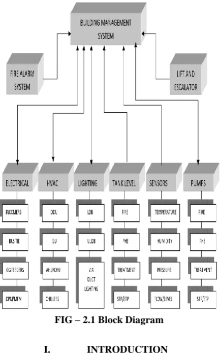
[image:1.595.61.278.251.599.2]ABSTRACT: A Building Management System is also known as Building Automation System (BAS), It is a Computer based control system installed in buildings that controls and monitors buildings mechanical and electrical equipment such as ventilation, lighting, power systems and security systems. A building management system for METRO includes inputs from the systems like HVAC (Heating Ventilation Air Conditioning), Lifts Escalators, UPS and Fire Alarm and Detection System etc. A Building Management system uses a PLC controller along with SCADA suite to monitor and control all the systems included in the Metro. BMS provides Automatic Fault Detection System and diagnosis strategies for building energy performance.
FIG – 2.1 Block Diagram
I. INTRODUCTION
of todays’ built environment and its facilities. BACS technology and its connectivity extends beyond just the large high rise commercial building, now adopted by industrial and smaller commercial buildings, and now even domestic residents. Primarily, the application of BACS is driven by the cumulative commercial need for increasing automation functionality and seamless flow of information across the organization, with a focus to reduce operating costs, and provide a more time responsive and safer facility. Revised Manuscript Received on September 05, 2019.
G. Pradeep, Pg Student, Mlr Institute Of Technology, Dundigal, Hyderabad
P. Chandra shaker,Pg Student, Mlr Institute Of Technology, Dundigal, Hyderabad
SVS Prasad, Pg Student, Mlr Institute Of Technology, Dundigal, Hyderabad
The market increase in BACS will further drive greater built environment connectivity, as operators and users seek and demand greater and easier end-user functionality. As BACS become more interconnected throughout the facility and its corporate business network, more complex vulnerabilities become embedded at the corporate level that elevate corporate risk exposure. BMS System in general is the computer based control system installed in buildings that controls and monitors the building mechanical BMS uses protocols such as C-BUS, PROFIBUS and so on. Building Management Systems are most commonly implemented in large projects with extensive mechanical, HVAC, Electrical Systems. Building Automation and Control Systems (BACS) and more recently, Intelligent Building systems, are becoming embedded and commonplace into much Systems linked to a BMS typically represent 40% of building’s energy lighting is included, this number approaches to 70%. BMS systems are linked to access control or other security systems such as closed circuit television. Various types of controls in BMS System include manual Control – Switches, dimmers. Basic automatic controls (open loop) – timers, Photo sensors. Basic automatic controls (closed loop)-Thermostat, humidistat, Programmable controllers (open loop or closed loop)- temperature, Pressure, level flow etc. (all closed loop).
II. BMS WORKING PROCEDURE:
Uppal depot is having two HMI work stations with redundant configuration which are connected through redundant network switches to independent redundant PLC system which in turn connected to 10 number of RIOs through multimode OFC ring network which are located in different locations of depot such as DCC, PHE pumps room, Annex building, Main work shop, STP etc. AOCC BMS is having two HMI work stations with redundant configuration which are connected through redundant network switches to independent redundant PLC system which in turn connected to 10 number of RIOs through multimode OFC ring network which are located at different floors. AOCC also having a central BMS servers and clients configured for distributed system, Disaster Recovery system (DRS), Oracle DB, Asset Management System (AMS) and Reports. OCC having two servers and one SAN and BCC having one server machine and one SAN (located at uppal depot) which are configured for DRS and servers storing historical data base in SAN (Storage Area Network).
2.1 Chiller Plant Manager (CPM)
The below figure shows the three chillers connected to AHUs/CAHUs along with flow meter data. system which is controlling three chillers (2 working and 1 standby). All scheduling, inlet/outlet water pressure, Primary and Secondary pumps are being
2.2 AIR HANDLING UNIT (AHU/CSU/FCU)
AHU is a main unit which circulates the chilled air into the connected rooms/area in a closed loop. It is mainly containing motorized drive/starter controlled fan, Coil tubing, 2-way valve, Filter, Inlet and outlet water pipeline openings.
AHU takes chilled water from chillers supply line which flows through its coil. Fan extracts the air through filter and passes it through coil due to which air temperature reduces and supplies the chilled air to connected rooms through supply duct, MSFD (Motorized Supply Fire Damper), MVCD (Motorized Volume Control Damper) and VAVs (Variable air volume). Return duct is connected from each room as a closed loop returning back to AHU room through MRFDs (Motorized Return Fire Damper). The fan speed of AHU can be controlled through drive connected to its motor through which supply duct pressure can be controlled and Temperature can be controlled modulating 2-way valve placed at chilled return water pipeline. All AHUs are being controlled and monitored by BMS.
Digital inputs required for typical AHU are: Local/Remote status (Selector Switch) VFD mode/Started mode (Selector Switch) Filter status (DPS)
Motor Running Status (DPS) Trip status (Electrical contact)
Analogue inputs required for typical AHU are: SAT (Supply Air Temperature)
RAT (Return Air Temperature) Duct Pressure
2 Way valve position
Analogue outputs required for typical AHU are: 2-way valve command
VFD frequency command
AHU POPUP WITH VFD PARAMETERS: VFD parameters are being read through serial RS485 protocol.
2.3 PID LOOPS:
There are two closed loop PIDs defined for each AHU, One for Temperature and other for Pressure. Both PID loops can be selected in Manual/Auto mode. In manual mode temperature can be controlled by giving manual set point for 2-way valve positions in percentage of opening and in auto mode auto set point to be given in required temperature value in °C. Similarly pressure PID can be
controlled through Auto/Manual set points. Where manual set point can directly control the motor RPM by giving fixed frequency given in percentage (0-100%:0Hz-50Hz) and Auto set point is to be given in pressure (Pa).
Process Value (PV) for temperature PID is return air temperature (RAT) value, set point for the PID in auto mode is being fed from HMI AHU popup and the output of PID (CV) value being sent to AO command to 2-way valve. In similar manner PV for Pressure PID is duct pressure value, set point for PID in auto mode is being fed from the HMI and the output of PID (CV) is moved to AO command to VFD frequency hardwired AI.
Filter DPS: Differential pressure switch is placed across the AHU filter which monitors the pressure across the AHU filter while AHU running and if pressure differs across the filter then it gets activated which means filter got choke/blocked and need to clean.
2.4 CSU (CEILING SUSPENDED AHU/FCU) (FAN COIL UNIT)
In comparison to AHU ceiling suspended air handling units are smaller in size used for smaller room air-conditioning. Usually this unit is suspended above false ceiling and hence the name suspended unit. The major difference between AHU and CSU is that it has got only temperature control through its 2-way valve whereas it’s Pressure cannot be controlled as it’s motor rotates with fixed speed without any drive control. Fan coil units much smaller in size and very compact units but the functionality sis similar to CSU. CSUs and FCUs can also be connected in same pipelines of chillers which are used for AHUs. A CSU and FCU popup is as shown in the below figures.
As shown in above figure CSU is having return air temperature (RAT) sensor through which coil temperature can be controlled in AUTO mode by providing set point in temperature °C and through its two-way valve required temperature can be achieved. FCU is a compact unit it is not having any SAT/RAT so its temperature only can be increased or decreased through manual set points in form of %.
2.5 VAV (Variable Air Volume)
Chilled air from the AHU is being controlled through VAVs. Each room or each work space temperature can be varied by setting required temperature locally from thermostat or from BMS HMI. BMS communicating to each VAV through Modbus RTU protocol. Each VAV contains a thermostat, temperature sensor, Modulating Dampers, CFM sensor. A set of VAVs connected to a VAV controller. Minimum fixed CFM is assigned each VAV in accordance to this modulating dampers opens in percentage to achieve the temperature set point. A
International Journal of Innovative Technology and Exploring Engineering (IJITEE) ISSN: 2278-3075,Volume-8 Issue-11, September 2019
DAMPERS
Dampers are basically valves which plays important roles to regulate air flow. Motorized dampers are being used at HMRL are,
MSFD (Motorized Supply Fire Damper) ---These dampers are located at supply line of the AHU. Normally remains open and will be operated based fire scenario.
MRFD (Motorized Return Fire Damper) ---These dampers are used in return line of AHU. Normally remains open based on fire scenario/philosophy will be operated.
MVCD (Motorized Volume Control Damper) ----MVCDs are used for controlling the flow of the air entering/returning into/from rooms.
MFFD (Motorized Fresh Fire Damper) ---- Used for fresh with or without fresh air fans.
MEFD (Motorized Exhaust Fire Damper) --- Used for exhaust with exhaust fans.
VRVs (Variable Refrigerant Volume)
All typical stations are having VRV system for HVAC. VRV system basically contains an ODU (Out Door Unit) and Number of IDUs (In Door Units) connected through pipes. Each station has 4 or more ODUs located above the arms of stations. Two ODU in working-standby combination connected to number of IDUs as per design. These IDUs data is being monitor and controlled by BMS through Modbus RTU protocol. In station only HVAC system differs from the depot other all systems are identical. Instead of chillers and AHUs in stations split unit AC, Cassette unit AC and CAHUs are used as an IDU (Indoor Unit) which are connected to the outdoor units (compressors). IDUs are displayed in accordance to their
locations. If AC running it will be in GREEN color and if stopped it will be in RED color as shown. On clicking AC object popup for IDU will be opened as shown below.
2.6 STATION FAS (FIRE ALARM SYSTEM)
Fire alarm integration with BMS has been done through Modbus TCP communication. All smoke detectors status is being displayed on FAS layout. The top navigation bar is having three buttons for FAS one for concourse FAS, second for Platform FAS and the third button is for street level FAS.
If fire detector activates in concourse zone, then only Concourse FAS button will start blinking in RED color and by clicking this button operator easily come to know which detector is activated.
Smoke detector is being displayed in three different colors. Steady GREEN color ………. Smoke detector is in normal state
Blinking RED color………. Smoke detector is activated (Alarm mode)
Steady YELLOW color………. Smoke detector is in Trouble (Power failure/Not detected in loop)
There are 12 number of detectors related to CGP in two room (SER&TER) where clean gas will be released on fire detection. These 12 detectors are shown with blue color background.
If any two of the fire detector in TER or SER room activated, then after 10 minutes BMS system will starts the clean gas exhaust fan and open exhaust fan damper. MRFD of TER and common MRFD will be opened if fire occurs in TER, Similarly MRFD of SER and common MRFD will be opened if fire occurs in SER. In normal conditions all three fire dampers remain closed and clean gas exhaust fan remains OFF.
During fire mode at concourse level air-conditioning supply will be cut off though VACDB (Part-B side) and from stage-2 onwards power through PDB will be cut off (Part-A side). Both ODUs are being turned off in stage-1 at part-A side. All exhaust/fresh air fans will be stopped and MRFDs will be closed. For interlocking stations both CAHUs power will cut off and all four MVCDs for CAHU will be closed. During fire mode at street level exhaust and fresh air fans will be stopped.
Typical SLD for electrical panel
Electrical panel SLD is shown in above figure in which incomers are only being monitored by BMS whereas outgoing feeders are monitored and controlled by BMS. The feeders which are in GREEN color are in open sate, the feeders which are in RED color are in close state. The feeders which are in yellow color are in trip state. If feeder is shown in black color, then it is not being monitored or controlled by BMS. On clicking on controlled feeder a popup will appear as shown in above figure which will allow operator to open/close the breaker. Open/Close buttons only enable if breaker is in remote state.
For incomers energy meters also being monitored as shown in the figure below. In which BMS fetching the data from energy meter on Modbus serial communication. Following are the DPM (Digital power meter) data being fetched and displayed on screen. Quick trend view window will be opened on clicking on any analogue value.
III. EXHAUST FAN OPERATIONS
ASS ROOM:
If ASS room temperature goes above 30 degrees then after 30 seconds first exhaust fan of ASS rooms will be started automatically from BMS and if temperature goes above 35 degrees then second exhaust fan of ASS room will also get started after 30 seconds. Both exhaust fans will be turned off if temperature comes down to 30 deg.
TOILET ROOM EXHAUST FAN
TOI-EX-01 fan will be automatically running from BMS during commercial activities of station if kept in auto mode and remote mode from field i.e. 8:00 AM to 5:00 PM. FRESH AIR FAN (Concourse and street level)
Fresh air fans will be running for two hours for every 6 hours. During fan running hours MFFD remains open and in normal state remains close.
FIRE PUMP ROOM EXHAUST FAN (EX-10)
If fire pump room temperature goes above 30 degrees then after 30 seconds exhaust fan EX 10 will be started automatically from BMS. Normally it remains OFF.
IV. CONCLUSION
Building Management system, when embedded throughout an organization, its strategy and operations, can drive value across a number of dimensions, information technology architecture are a seamless entity. They work in concert because they share resources and adhere to the same set of standards. This ideal scenario offers many benefits, including:
• Reduced management and infrastructure equipment cost. • Critical building system information is readily available at all levels of the enterprise.
• Employees can access and act upon this information without the constraints of a dedicated workstation at a fixed location.
• New services are possible that save time and preserve resources.
When making an investment in BMS technology, an organization should look beyond today’s configuration. Decision makers need to cast a wider net and recognize the advantages of merging the building automation system into the IT infrastructure. Whatever technology platform is selected to harness energy and operational data; it must be fully compatible with the IT network that is already in place. Allow the BAS to rely on the IT network as the data highway for safe and reliable transportation of information. In return, the IT staff will provide critical services for planning and maintenance.
REFERENCES
1. Swarnalatha P, “Building Management System Using Windows Communication Foundation and XAML” International Journal of 2. Engineering and Technology Vol.3 (2), 2011, 95-99
3. Ler, Eng Loo, “Intelligent Building Automation System”. Faculty of Engineering and Surveying
International Journal of Innovative Technology and Exploring Engineering (IJITEE) ISSN: 2278-3075,Volume-8 Issue-11, September 2019
Author-1 Photo
Author-2 Photo
5. Hamid Reza Naji, “Intelligent Building Management Systems using Multi Agents: Fuzzy Approach” International Journal of Computer 6. Applications (0975 – 8887) Volume 14– No.6, February 2011. 7. “Lighting control saves money and makes sense". Daintree
Networks.
8. http://www.daintree.net/downloads/whitepapers/smart-lighting.pdf. 9. Retrieved 2009-06-19
AUTHORS PROFILE
Pradeep Gandu was born in Hyderabad in the year 1991. I received B. Tech degree in Electrical and Electronics Engineering from Jawaharlal Nehru Technological University in the year 2014. I am currently perusing M Tech from MLR Institute of Technology.