Object-Oriented Design and
Implementation of Fault Management
Function for MPLS network
Sung-Jin Lim , Ryung-Min Kim, and Young-Tak Kim
Advanced Networking Technology Lab.
Dept. of Information & Communication Engineering
Graduate School Yeungnam University, Korea
Email: [email protected], [email protected], [email protected]http://antl. yu.ac.kr
Abstract
In this paper, we propose a fault management with fast rerouting restoration
scheme in MPLS network. The proposed scheme finds out the root cause of the
occurred fault, and provides differentiated service with guaranteed QoS (Quality
of Service) according to the differentiated backup path options. It can provide
various backup path options, such as 1:1, 1:N or M:N fast-reroute by NMS, and
operation modes, such as standby mode, path-option mode, based on the link/
node protection mechanism in Cisco router. The proposed fault management
scheme has been designed to be easily implemented in MPLS network composed
of multiple MPLS LSRs (Label Switched Router) of various vendors. We also
propose an efficient implementation scheme that can handle failure rapidly,
considering the link preemption priority among LSPs to improve the efficiency of
network resources, which is one of the most important performance factors of
fault restoration. The proposed scheme can guarantee the required bandwidth of
backup LSP.
Yeungnam Univ. ANTLab.
(2) APNOM 2003
Introduction
• Traffic engineering has been emphasized to offer end-to-end
QoS-guaranteed multimedia services in Next Generation
Internet.
• Fault restoration in traditional IP network vs. MPLS network
• The primary goals of fast restoration by fault management
function.
– QoS guaranteed differentiated path protection.
– Guaranteed bandwidth of backup LSP at fault occurrence.
• We propose a fault management with fast rerouting restoration
scheme in MPLS network.
– Design and implement differentiated path protection and link.
preemption priority among LSPs.
• Key technologies
– Traffic Engineering, Differentiated Service, Restoration, Protection, and
Object-Oriented Design.
1. Introduction
Recently, traffic engineering has been emphasized to offer end-to-end QoS guaranteed multimedia services in Next Generation Internet. MPLS can provide efficient traffic engineering by configuration of TE
(Traffic Engineering)-LSP (Label Switched Path) among MPLS LSRs[1].
In traditional IP network, the failure in link/node has been restored after long time delay from the fault occurrence by Link State Advertisement (LSA) of routing protocol, which is notified by flooding mechanism among adjacent routers, where each router changes routing table to by-pass the erroneous link or node. In MPLS network, unlike the connectionless IP network, we can achieve the fast restoration performance using protection switching function that establishes backup LSP for working LSP dynamically or explicitly[2].
In 1:1 or 1+1 path protection switching scheme, the backup path should be pre-established to provide the fast protection switching performance. However, the backup LSP for fast restoration is not used in normal traffic transmission until any failure occurs; thus, the reserved bandwidth of the backup LSP reduces the link utilization [3]. The primary goals of fast restoration by fault management function are (i) fast restoration of QoS guaranteed differentiated path, and (ii) the guaranteed bandwidth of backup LSP at fault occurrence.
In this paper, we propose a fault management with fast rerouting restoration scheme in MPLS network. We also propose an efficient implementation scheme that can handle failure rapidly, considering link preemption priority among LSPs to improve the efficiency of network resources. The proposed scheme can guarantee the required bandwidth of backup LSP.
The rest of this paper is organized as follows. In section 2, the related works on fault restoration model, fault management architecture, and the NMS for MPLS network are briefly explained and analyzed. In section 3, restoration techniques in fault management system are introduced briefly. In section 4, the overall architecture and the implementation details of the proposed scheme are explained. We evaluate the proposed system in section 5, and finally we conclude in section 6.
Yeungnam Univ. ANTLab.
(3) APNOM 2003
Related works
•
Fault restoration model
– Rerouting vs. protection switching
• Rerouting
• Protection switching :
– Pre-established backup path SRLG-disjoint with working LSP
– 1:1, 1:N, M:N, 1+1 path protection switching
– Local repair vs. path protection
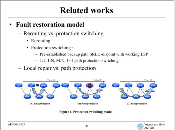
A B Working LSP C D E F G A B Working LSP C D E F G A B Working LSP C D E F G
(A) Link protection (B) Node protection (C) Path protection
Figure 1. Protection switching model
2. Related Works
2.1 Fault restoration modelFault restoration model can be classified into rerouting and protection switching. Protection switching scheme is classified into local fault restoration (link/node protection) and end-to-end path protection scheme. End-to-end path protection can be implemented by 1:1, 1+1, 1:N or M:N protection scheme [5-7].
The difference between rerouting and protection switching is the restoration time involved in providing the rerouting information to the restoration process. In the rerouting restoration scheme, rerouting paths are searched when the restoration process is invoked via the exchange of path searching messages and acknowledgement message. For the protection switching, rerouting information is computed periodically. Thus, rerouting information may be ready when a network component has failed and the restoration process is triggered[8]. The former scheme is usally slower in restoration speed than the protection switching scheme; but it has the advantage that does not waste network resources (until a fault occur) [9].
As shown in Figure 1, when a network has M edge nodes, the total number of recovery paths that must be
set up is proportional to M*(M-1). If all nodes within a network are equally likely to fail, this is clearly not a scalable solution. Therefore, if M is small, the path protection approach is more efficient than the local repair. However, in some cases, it is slower than local repair since it takes longer time for the fault notification message to reach to the protection switching point to trigger the recovery action[10]. So, NMS must select relevant protection switching model according to the network situation with efficient network resource utilization strategy.
Yeungnam Univ. ANTLab.
(4) APNOM 2003
Related works (cont.)
•
Fault Management Architecture of Next Generation Internet
– Fault Management Components in TINA
– Fault Management MOs in TMN
•
Fault Management Activities
– Alarm surveillance
– Testing
– Fault localization
– Fault correction
– Trouble administration
•
MPLS Fault Management System
– RATES,
– Cisco MPLS Tunnel Builder,
– Sheer Networks’ Broadband Operating Supervisor(BOS)
2.2 Fault Management Architecture of Next Generation Internet
So far, TINA system has been receiving attention by advantages of provisioning flexible interoperations
among heterogeneous devices and efficient communication network service[11]. TINA architecture has
accommodated the advantages of existing administration system such as TMN, OSI administration system, etc. In addition, TINA based DPE (Distributed Processing Environment) architecture has several characteristics, such as independency of lower part transmission technology and high reusability. TINA-C from ISO/OSI system management standards has the categorization of the management, called FCAPS. Fault management function should provide five activities such as alarm surveillance, testing, fault localization, fault correction, and trouble administration[12].
2.3 MPLS Fault Management System
RATES (Routing and Traffic Engineering Server) [13] supports restoration of LSPs. The primary
restoration goals for RATES are either complete path protection or path protection under single link failure. But, RATES does not support differentiated path protection or algorithm that restores failure on differentiated user traffic after failure occurrence.
Cisco MPLS Tunnel Builder[14] protects bandwidth of any primary LSP, regardless of when it was
established (before /after calculation). This is enforced through the tying of Tunnel Builder Pro primary bandwidth to an RSVP bandwidth pool. The backup path is actually signaled with 0 bandwidth on the network. It has advantage that can use network resources efficiently. The Cisco MPLS Tunnel Builder Pro has protection function only for link and node, but does not consider failure on each of LSPs of a port or node.
Sheer Networks’ Broadband Operating Supervisor (BOS) [15] provides instantaneous and highly accurate
fault detection coupled with root cause analysis, service impact analysis and service path tracing. But this also does not support differentiated protection function or algorithm that restore differentiated user traffic after failure occurrence.
Yeungnam Univ. ANTLab.
(5) APNOM 2003
Restoration Schemes
•
Differentiated Path Protection Option
– Example scenario of applying protection path options
according to MPLS service class.
•
Preemption Priority based restoration of LSPs
– Guaranteed bandwidth of backup LSP for the protected
working LSP.
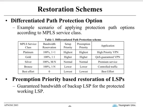
Best Effort Lowest Lowest 0 Best effort Lower Normal Higher Highest Preemption Priority Controlled traffic Premium service QoS-guaranteed VPN High Priority VPN Application Lower Normal Higher Highest Setup Priority 100%, 1:N 100%, M:N 100%, 1:1 100%, 1+1 Bandwidth Reservation Gold Bronze Silver Platinum MPLS Service ClassTable 1. Differentiated Path Protection scheme
3. Restoration Schemes
3.1 Differentiated Path Protection OptionIf each user wishes to satisfy SLA (Service Level Agreement), we must deal with differentiated path protection option. In SLA contract situation, failure occurrence in MPLS network will impact administrator as well as user. In this paper, we design and implement a restoration scheme that has high stability and providing differentiated protection path option. Table 1 shows an example of applying protection path option according to MPLS service classes.
3.2 Preemption Priority based restoration of LSPs [15]
Recently, we proposed fault restoration scheme that incorporate preemption priority mechanisms in MPLS
[16]. Cisco router provides two protection switching schemes [17-18]; standby path mode and path-option
mode does not guarantee the required bandwidth of backup LSP offering in working LSP. This problem can be solved by adjusting preemption priority among LSPs. Pre-establishing the link preemption priority of backup LSP can provide guaranteed bandwidth of backup LSP for the protected working LSP.
Yeungnam Univ. ANTLab.
(6) APNOM 2003
Design and Implementation of Fault
Management System
•
Fault restoration procedure with Managed Objects
(MOs)
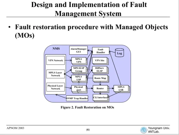
Figure 2. Fault Restoration on MOs
SNMP Trap Handler Fault Handler Router Router Router Route Map Route Map Route Map Physical port Physical port Physical port AlarmManager GUI MPLS LSP MPLS LSP MPLS LSP Physical Layer Network MPLS Layer Network VPN Network MPLS VPN MPLS VPN MPLS VPN Router Router MPLS LSR Router Router MPLSLSP Group Router Router CLI interface Router Router VPN Site Router Router DiffServ ELSP Log SNMP Trap Handler Fault Handler Router Router RouterRouterRouter Router Route Map Route Map Route MapRoute MapRoute Map Route Map Physical port Physical port Physical port Physical port Physical port Physical port AlarmManager GUI MPLS LSP MPLS LSP MPLS LSP MPLS LSP MPLS LSP MPLS LSP Physical Layer Network MPLS Layer Network VPN Network Physical Layer Network MPLS Layer Network VPN Network MPLS VPN MPLS VPN MPLS VPN MPLS VPN MPLS VPN MPLS VPN Router Router MPLS LSRRouter Router MPLS LSR Router Router MPLSLSP
GroupRouterRouter MPLSLSP Group
Router Router CLI interfaceRouterRouter CLI interface Router Router VPN SiteRouterRouter VPN Site Router Router DiffServ ELSPRouter Router DiffServ ELSP Log NMS
4. Design and Implementation of Fault Management System
4.1 Fault restoration approach through Managed Objects(MOs)Figure 2 shows MOs (Managed Objects) that handle fault control in NMS. It has a semantic connection between classes of which each relationship is implemented by association, dependency, unidirectional aggregation, generalization (inheritance) and realization among MOs. Each MO reduces overhead, and achieves each class different function using layered network management architecture with physical layer MO, MPLS layer MO, VPN layer MO and IP layer MO. Fault management modules are configured of three parts: SNMP trap handler part that receives event message from node, system core part that has the layered network logical MO, and GUI (Graphical User Interface) part that displays the physical and logical network topology.
Each LSPs, ports and LSRs MO for Fault Management are processed independently by individual MO, and is processed also individually after calling method about MO that is subordinate to relevant MO. Thus, Object-based NMS has advantage of easily expandable MO of network nodes or links.
For the alarm correlation, f
ault correlation function was implemented through each of MO’srelationship.
If the trap message received from SNMP trap handler has physical interface
information such as FastEthernet, Serial and POS, the physical layer MO checks the physical
node’s failure after checking the port information of the node’s MO, and checks did neighbor’s
node and port information with same method. If logical interface information such as tunnel, root
cause of failure is found through matching port’s MO status after checking each port information
that LSP's path passes.
Yeungnam Univ. ANTLab.
(7) APNOM 2003
Design and Implementation of Fault
Management System (cont.)
•
Fault Restoration Function
–
SNMP trap handler implementation
–
Alarm Manager GUI
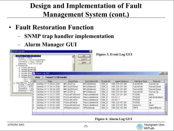
Figure 3. Event Log GUI
Figure 4. Alarm Log GUI
4.2 Fault restoration function in detail (1) SNMP Trap Handler Implementation
When a physical link/node or local link failure occurs, the SNMP trap handler only receives a notification message and obtains information related to the failure from the trap message for the alarm correlation. This message is analyzed to find the root cause of failure according to the variable binding information of notification messages through managed objects(MOs) that are a part of core module. Notification messages received by the SNMP trap handler are sent to the physical layer network, MPLS layer network, VPN network via XML-based interface of NMS core system.
SNMP trap handler receives notification messages with variable binding information such as trap type, trap reporting agent address, interface ID and local interface reason information that indicates the reason for interface last status change, and sends the notification information to its relevant MO. Then, according to the configuration of fault management strategy, NMS redirects the user packet flow from the ingress LSR to egress LSR through the backup LSP, or enable the routers to process the built-in fast protection switching.
Figure 3shows an example event reporting GUI for notification message with VBs (Variable Bindings) information from router that includes interface index, interface administrate status, interface operation status, interface type, and local interface reason.
(2) Alarm Manager GUI
Figure 4shows an example of alarm log reporting GUI for fault occurrence with its root cause. It is shown that date and time of failure occurence, alarm type, sub-network, Router ID of the failure occurrence, agent
Yeungnam Univ. ANTLab.
(8) APNOM 2003
Design and Implementation of Fault
Management System (cont.)
•
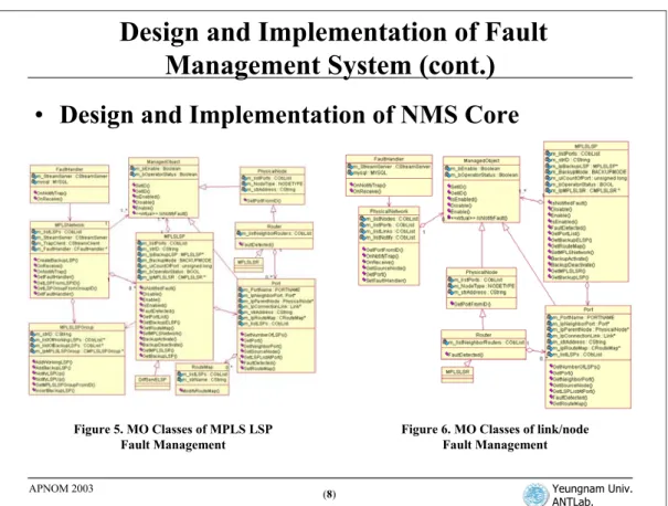
Design and Implementation of NMS Core
Figure 5. MO Classes of MPLS LSP Fault Management
Figure 6. MO Classes of link/node Fault Management
(3) Design and Implementation of NMS Core
The MOs for fault handler, physical network, physical node, port, physical link, MPLS network, MPLS LSR, MPLS LSP, and route-map have been implemented by object-oriented classes with carefully designed class-inheritance hierarchy for system expansibility. Figure 5 shows a part of class diagram for MPLS LSP fault management in NMS. In MPLS network MO, it has function that receiving information from SNMP trap handler, MPLS LSP group mapping function, and also has fault handler’s object reference information.
For each MPLS LSP, the operator can specify MPLS LSP group and protection path option according to the differentiated user traffic, such as 1:1, 1+1, 1:N, M:N, standby, path-option, fast-reroute or no protection. The backup LSP from ingress LSR to egress LSR is usually specified to be SRLG (Shard Risk Link Group)-disjoint for the working LSP. MPLS LSP group is used for checking LSP, which specifies path protection service among 1:1, 1:N and M:N.
The route-map has a filtering function to transmit traffic that enters the inbound port using access-list information. Route-map included in MPLS LSP access-lists is obtained by access to port's MO. In fault handler MO, abnormal conditions, logical LSP and link/node failures are recorded in fault management log records.
Figure 6 shows a part of class diagram for link/node fault management in NMS. When a link/node failure is notified from a specified MO, the failure is processed by the specified link/node MO in physical network. As soon as the affected LSPs of the erroneous link/node are checked, they are promptly rerouted by either the pre-configured backup LSPs, or by the reroute command through CLI (Command Line Interface) from NMS.
Yeungnam Univ. ANTLab.
(9) APNOM 2003
Performance Analysis of Fast Restoration
•
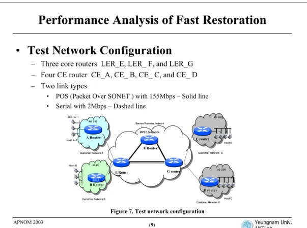
Test Network Configuration
– Three core routers LER_E, LER_ F, and LER_G
– Four CE router CE_A, CE_ B, CE_ C, and CE_ D
– Two link types
• POS (Packet Over SONET ) with 155Mbps – Solid line • Serial with 2Mbps – Dashed line
Customer Ne twork A F Router 3620_D AS 400 Customer Ne twork B MPLS Network
Service Provider Ne twork AS 300 Host A-1 Host B AS 200 Host D Customer Ne twork C AS 500 Customer Ne twork D Host C G router E Rouer A Router B Router C router D router Host A-2
Figure 7. Test network configuration
5. Performance Analysis of Fast restoration
We evaluated the proposed fast restoration scheme with three core routers of Cisco 7204 series in service provider network, and CE routers (Customer Edge - A, B, C and D router) that are connected to PE (Provider Edge - E and G router). Link between PE and P (Provider core router, F) is connected by POS (Packet Over SONET) of 155Mbps. Link between E and G router has two kind of link type ; POS and serial with 2Mbps. The serial link is used for measuring link preemption. Each MPLS LSP is configured according to following differentiated protection options.
For measuring fault restoration, we generate failure intentionally by node power off, port cutting and administrative shutdown command through CLI by operator.
Working LSP Bandwidth / Packet size Rema rk Backup LSP path Wo rkin g LSP path Pr ot ec tio n Sc he m e
Yeungnam Univ. ANTLab.
(10) APNOM 2003
End-to-end Performance Comparisons of
Differentiated Protection Options(1)
•
End-to-end Performance Comparisons of Differentiated
Protection Options
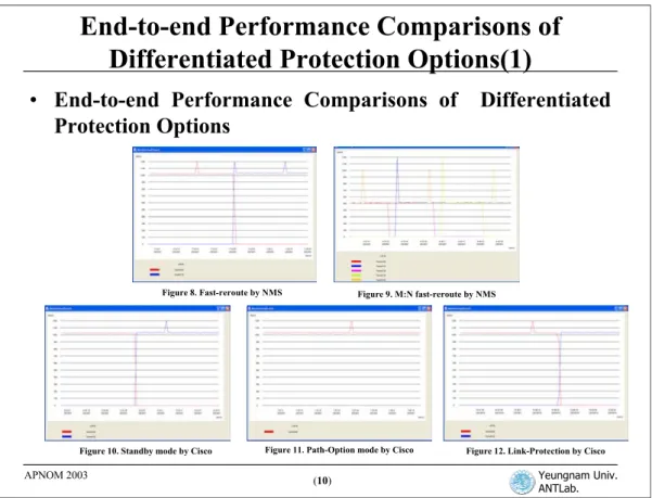
Figure 8. Fast-reroute by NMS Figure 9. M:N fast-reroute by NMS
Figure 10. Standby mode by Cisco Figure 11. Path-Option mode by Cisco Figure 12. Link-Protection by Cisco
5.1 End-to-end Performance Comparisons of Differentiated Protection Options
We measured the MPLS LSP restoration times and switching operations between the working LSP and the backup LSP.
(1) 1:1 fast-reroute restoration by NMS
On detection of a failure, it restores rapidly with protection switching time about 8 ms (packet loss:
1000bytes, transmission rate per packet: 1/125=0.08s). Figure 8shows the throughput of 1:1 fast-reroute by
NMS.
(2) 1:N and M:N fast-reroute by NMS
In order to generate fault intentionally for multiple link failures, we used shutdown command through CLI on each LSP. At the shutdown of third working LSP, the working LSP is not restored by backup LSP, because there is no more remaining backup LSP. The measured results of 1:N and M:N options show equal performance with 1:1 fast-reroute by NMS. The 1:N and M:N fast-reroute by NMS are usually pre-configured for lower traffic service as shown in Table 1.
(3) Standby mode by Cisco
Figure 10shows the throughput of standby mode by Cisco.
The result shows equal performance with
1:1 fast-reroute by NMS. The only different point is slow beginning time of protection switching
because of the signaling among routers. But, packet loss is almost same with 1:1 fast-reroute by
NMS because of the Cisco router buffer.
Figure 10
shows the throughput of standby mode by Cisco.
(4) Path-option mode by Cisco
When failures occurred, a new LSP with same working LSP attribute (LSP ID, bandwidth, priority, destination IP address, etc) is created. So, as long as other alternative route exists , the working LSP is
Yeungnam Univ. ANTLab.
(11) APNOM 2003
End-to-end Performance Comparison by
Differentiated Protection Options
•
Differentiated Restoration performance by precedence
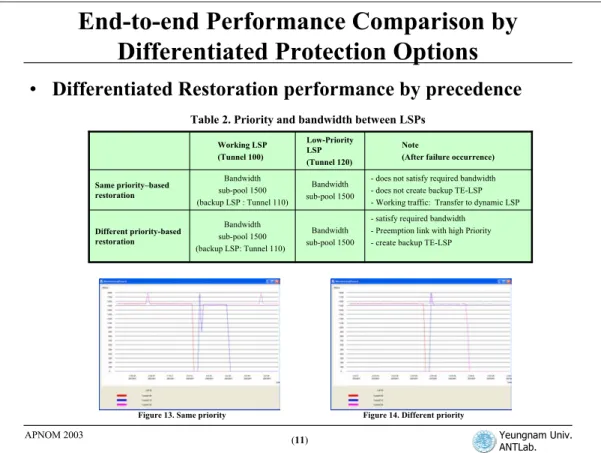
Figure 13. Same priority Figure 14. Different priority
- satisfy required bandwidth - Preemption link with high Priority - create backup TE-LSP Bandwidth sub-pool 1500 Bandwidth sub-pool 1500 (backup LSP: Tunnel 110) Different priority-based restoration
- does not satisfy required bandwidth - does not create backup TE-LSP - Working traffic: Transfer to dynamic LSP Bandwidth sub-pool 1500 Bandwidth sub-pool 1500 (backup LSP : Tunnel 110) Same priority–based restoration Note
(After failure occurrence) Low-Priority
LSP (Tunnel 120) Working LSP
(Tunnel 100)
Table 2. Priority and bandwidth between LSPs
5.2 Differentiated Restoration performance by precedence
This scheme is configured that lower-priority LSP with 1.5Mbps bandwidth in the same link, where the backup LSP of the high priority working LSP is created, and then we measured how the established bandwidth changes according to the precedence of LSPs after failure occurs. We configured the differentiated restoration schemes as shown in Table 2, and we do not used POS links with 155Mbps but use serial links with 2Mbps to test preemption link protection.
(1) Same priority-based restoration
Figure 13 shows the restoration performance for the same priority scheme between working
LSP(E→F→G) and another LSP(E→G) in the link where backup LSP is established. Even when the
working LSP is failed, the backup LSP is not created because there is no more remaining bandwidth in the link. From this result, we can understand that a performance degradation may occur between same priority LSP.
(2) Different priority-based restoration
Figure 14shows restoration performance for different priority scheme between high-priority working LSP
and lower-priority LSP. Comparing with Figure 13, the backup tunnel 110(bandwidth 1.5Mbps) preempts
link (2Mbps) bandwidth because the backup LSP has higher priority than tunnel120 with lower priority. The lower-priority LSP (tunnel120) that has occupied 1.5Mbps is preempted from the TE-LSP. Furthermore, the low priority traffic is not transmitted through MPLS-TE LSP, but through dynamic LSP just as the best effort scheme.
Yeungnam Univ. ANTLab.
(12) APNOM 2003
Conclusion
• We proposed an object-oriented design and implementation
scheme for
– 1:1, 1:N, M:N fast-reroute by NMS
– Standby mode, Path-option and link/node protection scheme in Cisco
MPLS Routers.
• The Proposed Fault Management Scheme for MPLS Network
Provides
– Reliability that guarantee the required bandwidth of backup LSP after
fault restoration
– Differentiated protection path option
– Object-Oriented MO design and implementation of network nodes and
links for better expansibility with equipments form various vendors.
6. Conclusion
In this paper, we proposed an object-oriented design and implementation of fault management function to handle link and node faults efficiently in MPLS network. We also proposed a scheme to guarantee differentiated service QoS according to the differentiated path protection options, such as 1:1, 1:N or M:N fast-reroute by NMS, standby mode, path-option, and link/node protection scheme by Cisco MPLS routers. The restoration times of fast reroute schemes were measured to be around 8ms in a test bed network with Cisco MPLS routers.
The fault restoration schemes proposed in this paper helps to improve the efficiency of network resources. There are several advantages: reliability that guarantees the required bandwidth of backup LSP after fault restoration, provisioning of differentiated protection path option, and object-based MO design of network nodes and links to adapt new network node/links from different vendors and to provide advantage of easily expandable.
References
[1] Osborne Simha, “Traffic Engineering with MPLS,” Cisco System, 2001.
[2] S.makam, V.Sharma, K.Owens, C.Huang, “Protection /Restoration of MPLS Networks”, IETF internet draft, Oct.,1999. [3] Peter Tomsu, Christian Scmutzer, Next Generation Optical Networks, Prentice Hall PTR, 2002.
[4] Youngtak Kim, "DoumiMan (DiffServ-over-universal-mpls internet Manager) for Guaranteed QoS Provisioning in Next Generation Internet,“ Proceedings of ITRC Forum 2003, June 4, 2003.
[5] Vishal Sharma et.al., “Framwork for MPLS-based Recovery,” IETF Internet Draft, May 2001.
[6] Ken Owens et.al., “A Path Protection /Restoration Mechanism for MPLS Networks,” IETF Internet Draft, July 2001.
[7] Dimitry Haskin, Ram Krishnan, AxiowaveNetworks, “A Method for Setting an Alternative Lable Switched Paths to Handle Fast Reroute,” IETF Internet Draft, 2000.
[8] Hae-Joon, Shin, “Segemtn-based Restoration Scheme for Efficient Fault Managements of Internet Transit Network,” doctor’s thesis, December, 2002. [9] Tong-Ho Wu, Noriaki Yoshikai, ATM Transport And Network Integrity, 1stEd., Academic Press, San Diago, 1997.
[10] ChangCheng Huang, Vishal Sharma, Ken Owens, Srinivas Makam, “Building Reliable MPLS Networks Using a Path Protection Mechanism,” IEEE Communication Magazine, March 2002.
[11] TINA-C, Overall Concepts and Principles of TINA, Ver 1.0, Feb. 1995. [12] TINA-C Deliverable, “Network resource Architecture Ver3.0,” Feb.1997.