Microfluidic Technologies for High-Throughput
Screening Applications
Thesis by Todd Thorsen
In Partial Fulfillment of the Requirements For the Degree of
Doctor in Philosophy
California Institute of Technology Pasadena, California
2003
I came to Caltech with what many people described as “crazy ideas.” Coming from a Masters degree in Public Health (M.P.H.) from the University of California at Berkeley, I was interested in developing high throughput diagnostic technology for infectious agents that would replace expensive, state-of-the-art equipment out of reach to most public health laboratories. This was the beginning of my journey at Caltech, a journey that took me through a wide range of disciplines and a large number of laboratories. At Caltech, I really learned about the true meaning of collaboration as I struggled to build up my vision one piece at a time. Without the help of numerous professors and students, my work would have never been possible.
First, I would like to thank all of my advisors, who became like family over the past five years. I am forever in their debt for not only giving me access to resources within their laboratories, but also for patiently listening to my ideas and giving me moral support in times where it seemed like all paths led to failure. I would like to thank Dr. Richard Roberts for all of his valuable combinatorial chemistry advice and the generous use of lab space and supplies during my early polymer development work, and Dr. Frances Arnold for introducing me to the world of complex systems. I am deeply grateful to Dr. Stephen Quake, who stood by my side countless times, patiently giving me advice on a large variety of subjects, ranging from microfluidics to optics and electronics.
Georgiou for allowing me to work at his laboratory at the University of Texas at Austin on the flow cytometry study of bacterial enzyme systems.
Finally, I would like to thank all of the graduate and postdoctoral students that worked alongside me for their help in numerous situations where I just didn’t have the technical expertise to go the distance alone. I would like to thank Dr. Mark Unger and Dr. Hou-pu Chou for their discussions and help in the area of microfabrication. To Sebastian Maerke, I am grateful for the days and nights he worked with me on setting up the valve and optomechanical systems. Finally, thanks to Dr. Markus Enzelberger for his work on the enzymatic screening systems in droplets. To all of you and countless others, I could not have done it alone.
Todd Thorsen
Pasadena, California
April, 2002
Abstract
In this thesis, I present a strategy for the design and development of microfluidic devices for high-throughput screening applications, such as mutant enzyme libraries expressed in prokaryotic hosts, where a few point mutations at the DNA level translates to hundreds of thousands of enzyme variants. The work falls into three main sections. Section I
Acknowledgements iii
Abstract v
1 Overview 1 1.1 Introduction 1
1.2 Organization 3
2 Polymers and Microfluidics: Chemical and Mechanical Properties 5
2.1 Introduction 5
2.2 Specific Polymer Properties 8
2.2.1 Silicone-based Polymers 8
2.2.2 Diene-based Polymers 19
2.2.3 Polyurethane-based Polymers 25
2.3 Conclusions 31
3 Microfluidic Crossflow: Dynamic Droplet Formation Technology 33
3.1 Introduction 33
3.2 Microencapsulation 35
3.2.1 Bulk Emulsions 37
3.2.2 Microfluidic Crossflow 43
3.3 Microfluidic Crossflow: Theory and Fluid Mechanics 56
3.4 A Variation on a Theme: In-line Droplet Generation 65
3.5 Droplet Sorting 70
3.5.2 Multilayer Soft Lithography: Elastomeric Valves 78
3.6 Detection: Development of a Fluorescence-Activated Droplet Sorter 85
3.7 Conclusions 92
4 Microfluidic Crossflow: Biochemical Screening Applications 94
4.1 Introduction 94
4.2 Principle and Design 95
4.3 Model Enzyme System: P-Nitrobenzyl Esterase in E. coli 97
4.4 Encapsulation and Assay Mechanics 99
4.5 Droplet Assay Troubleshooting 101
4.5.1 Flow Balance 102
4.5.2 Cell Adhesion to PDMS 104
4.5.3 Substrate Autohydrolysis 107
4.6 Conclusions 108
5 Complex Addressable Microfluidic Arrays 109
5.1 Introduction 109
5.2 Microfluidic Large Scale Integration 110
5.3 Microfluidic Multiplexors 112
5.4 Microfluidic Memory Storage Device 118
5.5 Microfluidic Comparator 121
5.6 Conclusions 126
6 Complex Microfluidic Arrays: Biochemical Assays 127
6.1 Introduction 127
6.3 Detection Systems for Array-Based Microfluidic Chips 130
6.4 Cytochrome c Peroxidase: Array-based Enzyme Library Screening 135
6.4.1 CCP Expression System 136
6.4.2 Random Mutagenesis: Library Construction 137
6.4.3 CCP Library Assay: Bulk vs. Microfluidic 138
6.5 Conclusions 146
Appendix A: Component List for Optical Valve 149
Appendix B: Schematic for Solid-State FACS 151
Chapter 2
2.1 Structure of repeating PDMS subunits. 8
2.2 Peroxide-based mechanism for PDMS cross-linking. 9
2.3 Platinum-based mechanism for PDMS cross-linking. 9
2.4 Fabrication of one-layer PDMS devices fabricated from a wet-etched 12
silicon wafer master mold 2.5 Schematic for introducing solvent test fluids into the PDMS microfluidic 13
devices. 2.6 Ruthenium-based Grubb's catalyst for ROMP reactions. 20
2.7 Dicyclopentadiene polymerization mechanism. 20
2.8 Clamping apparatus for solvent testing in polyDCDP microfluidic device. 22
2.9 Urethane linkage diagram formed by the addition polymerization of a 26
diisocyanate and a dialcohol group. 2.10 Urethane diacrylate oligomer. Reactive terminal vinyl groups are activated 27
during polymerization. 2.11 Photodegradation of 1-hydroxycyclohexyl phenyl ketone. 29
Chapter 3 3.1 Water/oil/surfactant phase diagram. 37
3.2 Light microscope images of reverse micelles in various oils. 39
3.3 Basic stages of crossflow membrane emulsification. 41
3.4 Experimental setup for capillary-based crossflow (w/o) emulsification 42
3.6 Effect of surfactant on droplet formation in a simple "T" junction 46 polyurethane device.
3.7 Surfactant-free microfluidic crossflow in square T- channel Ebecryl 270 47 microfluidic device using decane and water.
3.8 Relationship between water droplet size and breakoff frequency in a simple 48 "T" junction polyurethane microfluidic device using pressurized decane and water.
3.9 Layout for solenoid valve driven pump for pulsed droplet formation. 49
3.10 Soleniod driver schematic. 50
3.11 Solenoid-driven crossflow. 50
3.12 Crossflow using restricted "T" polyurethane microfluidic device to generate 51
3.13 Dual-T microfluidic mixer layout. 52
3.14 Dual-T microfluidic mixer. 53
3.15 Microfabricated channel dimensions at the point of crossflow and 55 photomicrograph of water introduced into the continuous oil-surfactant phase.
3.16 Reverse vesicles in square channels. 59
3.17 Droplet patterns in rounded channels at different water and oil/surfactant 61 pressures.
3.18 Predicted vs. actual drop size at different water and oil/surfactant pressures. 63 3.19 Inline microfluidic droplet generating device design. 67
3.20 Inline Ebecryl 270 microfluidic device. 68
3.22 Optical trap dynamics. 71 3.23 Central board layout of optical valve system. 74 3.24 Optics/detector head of optical valve system. 75
3.25 Trapping efficiency of 808 nm laser diode. 77
3.26 The first monolithic valve prototype developed in the Quake laboratory 79 at Caltech.
3.27 Multilayer soft lithography. 81
3.28 Schematic of silicone crossflow device with incubation cavity. 82
3.29 Sorting in cavity-based crossflow device. 84
3.30 Microfluidic droplet sorter. 88
3.31 Functional diagram of droplet sorter. 89
3.32 Single-color droplet formation at the crossflow junction. 90 3.33 Detector region during the two-color droplet sorting process in a 91 microcavity crossflow device.
Chapter 4
4.1 Microfluidic channel layout in a microfluidic crossflow for single cell 96 catalysis measurements.
4.2 Serpentine channel design for biochemical screening chip. 97 4.3 The conversion of fluorescein diacetate to fluorescein. 98 4.4 Encapsulated bacteria in droplets generated by microfluidic crossflow. 100 4.5 Monodisperse droplets containing E. coli expressing recombinant pNB 101 esterase and fluorescein diacetate substrate.
4.7 Restricted crossflow pattern designs to minimize crosstalk between the 104 two aqueous input lines.
4.8 Bugbuster sheared into mineral oil / 2% Span 80 in a Sylgard 184 106 crossflow device.
Chapter 5
5.1 Multiplexor control in a multilayer elastomeric microfluidic device. 112
5.2 1024 well serpentine chip schematic. 114
5.3 Detailed diagram of flow channel layout in high-density array region of 115 serpentine chip.
5.4 Compartmentalization of sample using the array sandwich valve in the 115
serpentine chip.
5.5 Sequential row purging of the high density chamber array using multiplexor 117 control.
5.6 Microfluidic memory chip. 118
5.7 Mechanics of a single chamber purge within a single row of the 120 microfluidic memory chip.
5.8 Demonstration of microfluidic memory display. 120
5.9 Microfluidic comparator chip. 121
5.10 Comparator chip mechanics in chambers of single column. 123
5.11 Microfluidic comparator diagram. 123
5.12 Chip in comparator mode. 124
6.1 eGFP transcription/translation in the array-based 1024 well serpentine 129 microfluidic device.
6.2 XY scanner stage layout. 132
6.3 Image map of the array of fluorescein-filled compartments in the 133 serpentine microfluidic chip.
6.4 Activity profile of wild-type cytochrome c peroxidase (CCP) single 139 colonies vs. CCP mutants generated by error-prone PCR using
Amplex Red substrate.
6.5 GenePix array scans of wild-type CCP and 0.25 mM MnCl2 141 CCP mutant library in Amplex Red substrate mix.
6.6 Cell number vs. activity profile for wild type CCP in the 1024 well 142 serpentine microarray chip.
6.7 Cell number vs. activity profile for the 0.25 mM MnCl2 CCP library 142 in the 1024 well serpentine microarray chip.
Chapter 2
2.1 Solvent resistance properties of bulk silicone (RTV 615). 11 2.2 Microfluidic solvent resistance (RTV 615). 14 2.3 Dicyclopentadiene/ 1,5-cyclooctadiene co-polymer study. 24 Chapter 3
3.1 Defect propagation speed in polyurethane crossflow device with water and 65 hexadecane/2% span 80.
Chapter 4
4.1 Surfactant and additive effects on whole cell E. coli expressing recombinant 105
pNB esterase.
Chapter 6
6.1 1024 compartment serpentine microfluidic chip assay activity levels. 143 6.2 1024 compartment serpentine microfluidic chip: background- 144
subtracted single-cell CCP activity levels.
Chapter 1 – Overview
1.1 Introduction
Technological advances in chemical engineering and molecular biology have opened up a whole new world in which we can generate millions of unique compounds through combinatorial techniques. The diversity of these systems drives the need for efficient high-throughput screening (HTS) technology. However, characterization of these
systems is far from a trivial process. Several platforms have emerged in the last few years to array or compartmentalize chemical libraries, including high-density 3456 well
microtiter plates1, bead-based optical fiber arrays2, and high-density bead-based
combinatorial libraries3. Unfortunately, the sophistication of the assay techniques has led
to increasingly complex and expensive support instrumentation, with the bulk of
industrial research going into miniaturizing microplates, building better robots to handle microplates, engineering better fluid dispensers, and building detection units capable of reading the “ultraminiaturized” plates4.
The emergence of “lab-on-a-chip” microfluidic systems offers an exciting new platform for HTS technologies5. Unlike high-density microplate systems, often referred to as µHTS because of their ability to screen compounds in microliter-sized sample
being a mature technology, there is still a lot of work to be done to optimize microfluidic devices for HTS applications. State-of-the-art commercial microfluidic devices are principally made by the micromachining of silicon9 and glass, and rely on electroosmotic flow10,11 to drive liquid through the channels, requiring high salt concentrations and a voltage source. This process generates gas bubbles, creating ionic conditions that are far from optimal for assays like enzymatic activity or protein-protein binding interactions. Other problems with hard polymer microfluidic devices include the need to build up layers to efficiently seal the channel networks, making layer-layer adhesion a serious concern during the fabrication process, and the lack of a good compartmentalization technology for the large scale analysis of chemical or biological libraries.
The goal of this thesis is not to offer the solutions for specific screening problems, but rather to offer a general platform for addressing them. I describe the development of microfluidic devices for HTS applications having highly flexible parameters; a
microencapsulation device suitable for aqueous solutions as well as organic solvents and a series of microfluidic devices with integrated elastomeric valves that function as high- density addressable arrays with picoliter volumes. Both of these systems create individual microenvironments with high informational content where thousands of single cells or small molecules such as DNA or proteins can be individually compartmentalized and examined. Model biochemical systems are presented to illustrate their potential as screening and selection tools in combinatorial assays such as recombinant enzyme libraries generated by random mutagenesis.
development. To this end, I present the research in this thesis from its “foundations,” starting with the essential material components of the microfluidic devices, the polymers, transitioning to the design and development of each type of device, and finally to its applications. An organizational layout of each chapter follows for easy reference.
1.2
Organization
Chapter 2. Polymers and Microfluidics: Chemical and Mechanical Properties
Several polymeric materials are explored as materials for microfluidic devices. Properties such as swelling in organic solvent, elasticity, and adhesion are explored.
Chapter 3. Microfluidic Crossflow: Dynamic Droplet Formation
The technique of generating droplets in a two-phase microfluidic system is outlined. Initial discussion focuses on design and fabrication techniques, followed by theoretical work in which a predictive model is proposed to describe the droplet formation.
Chapter 4. Crossflow: Biochemical Screening Applications
A modified design of the original microfluidic crossflow device is presented for HTS applications using a model enzyme in a bacterial expression system. Physical parameters such as flow balance and surfactant effects on the system are addressed.
Chapter 5. Complex Addressable Microfluidic Arrays
mulitplexors is described, creating addressable fluidic networks. Building on this
technology, microfluidic large-scale integration (µLSI) is discussed, enabling hundreds of
fluid channels to be controlled with few external components. Finally, the design, fabrication, and mechanics of several elastomeric prototypes for HTS are introduced.
Chapter 6. Complex Microfluidic Arrays: Biochemical Assays
Applications for the complex addressable microfluidic array devices are discussed,
including in vitro protein synthesis and bacterial enzyme expression systems. Emphasis is placed on both screening strategies and the development of detection systems to
Chapter 2 - Polymers and Microfluidics: Chemical and
Mechanical Properties
2.1
Introduction
Polymers are the most promising materials for microfluidic technologies since they can be used in mass replication technologies such as hot embossing, injection molding, laser micromachining, and casting12. The choice of polymer for a microfluidic device depends on its specific application. Polymers exhibit a wide range of mechanical properties, i.e., elasticity, hardness and brittleness, temperature stability, chemical resistance, and optical characteristics. Given the wide spectrum of available polymers, there is an acceptable material for nearly every application.
polymer chains become unstable, and thermal cracking begins to occur, leading to mechanical failure13.
An important characteristic of a polymer is its glass transition temperature, Tg. When a polymer is cooled below this temperature, it is solid. Some polymers are used below their glass transition temperatures, like polystyrene and poly(methyl methacrylate) with Tgs well above 100°C, where they are hard and brittle. Other classes of polymers, such as elastomers, are used above their Tgs in a rubbery state, exhibiting properties such as softness and flexibility14. For fabrication processes, where the polymer is cast or injection molded, Tg is a very important parameter. As the temperature is increased over Tg, it is in a viscoelastic state and can be easily molded12. Removing the polymer from the mold prior to cooling below the Tg can be extremely detrimental, affecting the geometric stability of the molded pattern. Softeners can be used to lower the glass transition temperature and facilitate molding at lower temperatures. However, they chemically weaken the polymer matrix by intercolating between the polymer strands or by acting as chain termination elements.
Plastics can be classified into three categories based on their molding behavior, which is based on the manner that the monomers interconnect within the polymer chains. (i) Thermoplastic polymers. These polymers primarily consist of entangled chains of linear polymers. As the strands are typically long and unbranched, cross-linking between strands rarely occurs. They are relatively soft and can be easily deformed. At
backbones of these polymers are sterically less hindered than the thermoplastic polymers, allowing greater flexibility around the backbone. For example, the silicone polymers, of which poly(dimethylsiloxane) is an example, have very low Tg values (in this case - 123°C) because the Si-O-Si linkage is very flexible and deformable. In response to an external force, elastomeric materials are readily stretched, but return to their original state (higher entropy) when the force is removed. (iii) Duroplastic polymers. These polymers are characterized by a high degree of cross-linking. It is necessary to cast these materials into their final shape using monomer and catalyst. The resulting product is typically hard and more brittle than thermoplastics. Examples include dicyclopentadiene and calcium fluorine polymers.
2.2
Specific Polymer Properties
Prior to designing actual functional microfluidic devices, I examined the physical and chemical properties of several polymers and polymer blends to find a material that would be suitable for my applications. As my original concept for a microfluidic
devices for sorting DNA and cells using electrophoretic techniques10, so this provided a natural starting material for my early studies. As PDMS proved to have inadequate chemical resistance against most oils, exhibiting swelling and degradation, my work broadened to investigate other groups of polymers, including dienes, urethanes and block co-polymers. A summary of this research follows.
2.2.1 Silicone-based Polymers
Silicone is a generic term for an entirely synthetic polymer containing a repeating Si-O backbone. The organic groups attached as side chains via silicon-carbon bonds define the class of the silicone16. Depending on the chain length and the nature of the organic groups, silicones can exist as emulsions, lubricants, fluids, resins, or elastomers. The most common and widely used elastomer is PDMS, having the basic repeating unit, [(CH3)2SiO] (Figure 2.1).
Figure 2.1: Structure of repeating PDMS subunits.
Polydimethylsiloxane (PDMS)
Structure and Mechanical properties
Silicone-based polymers such as PDMS have become a popular material for replica molding and stamp making using soft lithography techniques17. Classified as an
yet much more flexible than traditional micromachined materials like silicon (Y = ~1 GPa). The Young's modulus of PDMS depends on the extent of cross-linking between linear silicone chains. The cross-linking reaction is initiated by organic peroxides (Figure 2.2) or rare metal catalysts such as platinum (Figure 2.3). Silicones cross-linked by organic peroxides are typically one-part systems. The pre-catalyzed mixture consists of linear silicone chains and the peroxide catalyst. Curing is accomplished by heating the
Figure 2.2: Peroxide-based mechanism for PDMS cross-linking
mixture to break down the peroxides into free radicals, which initiate cross-linking between the side chain groups. The cure time depends on the activation temperature of the peroxide catalyst and the thickness of the part. The second method for curing silicone rubber utilizes a silicone hydride (SiH) cross-linking agent in conjunction with
methylvinyl silicone polymer. In the presence of a precious metal catalyst such as platinum, a true addition reaction occurs, resulting in a uniformly vulcanized rubber without curative by-products18. As this reaction occurs quite readily at room temperature, the silicone precursor is sold as a two-part system, with one part containing the Pt
crosslinking agent combined with silicone hydride substituted monomers and the other consisting predominantly of methylvinyl-based silicones, that is mixed just prior to casting. Crosslinking efficiency is affected by the spacing between the hydride groups and as well as the vinyl level of the precursors.
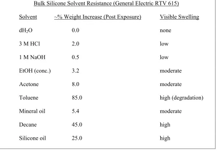
Chemical Resistance
PDMS is intrinsically hydrophobic, with the advancing contact angle of water at ~110°C. Its elastomeric structure makes it susceptible to swelling not only to alkanes, but also to halides, and strong acids and bases. Relative bulk swelling of PDMS was carried out in several solvents by immersing approximately 1 gram samples of the polymerized silicone (General Electric RTV 615 (10:1 part A:B)) in solvent and comparing their weight before and after (15 min) exposure to solvent (Table 2.1). However, these chemical resistance values were obtained using bulk polymer and provide only a rough estimate of the chemical compatibility of a particular solvent on the microfluidic scale.
Bulk Silicone Solvent Resistance (General Electric RTV 615)
Solvent ~% Weight Increase (Post Exposure) Visible Swelling
dH2O 0.0 none
3 M HCl 2.0 low
1 M NaOH 0.5 low
EtOH (conc.) 3.2 moderate
Acetone 8.0 moderate
Toluene 85.0 high (degradation)
Mineral oil 5.4 moderate
Decane 45.0 high
[image:25.612.105.549.74.385.2]Silicone oil 25.0 high
Table 2.1: Solvent resistance properties of bulk silicone (RTV 615)
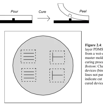
To fabricate the silicon master mold, a silicon wafer was patterned and chemically wet-etched. A virgin <100> silicon wafer with a thin oxide layer was spin-coated with a thin layer of photoresist (SJR 1813, Shipley), soft baked at 85°C for 30 minutes, and
subsequently patterned using a UV contact mask aligner with parallel lines and "T"
Pour Cure Peel
Figure 2.4: Fabrication of one-layer PDMS devices fabricated from a wet-etched silicon wafer master mold. Top: Casting and curing process for PDMS. Bottom: Channel mold for four devices (bird's eye view). Dotted lines not part of mold, but rather indicate cut positions to remove cured devices from mold.
anisotropic etch with KOH (50 g solid KOH in deionized water) at 50°C for 30 minutes
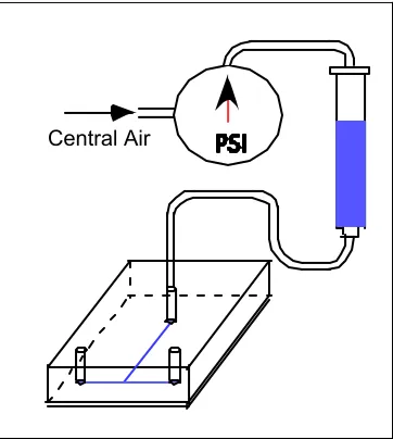
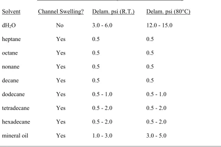
Flow tests were conducted with the devices using a syringe filled with the test solvent connected to a regulated pressure source (Figure 2.5). The syringe was connected to the PDMS chip via tygon tubing terminated with a 1.0 cm length of blunt end 23G
hypodermic tubing (O.D.= 635 µm), which tightly fits into the punched fluid input port. Fluid was introduced into the chip by adjusting the pressure on the regulator. The input pressure range was varied from 0.5 to 15.0 psi using PDMS chips sealed at either room temperature or baked at 80°C. As the design goal was to engineer microfluidic devices through which we could flow oil-water mixtures, solvent compatibility tests were conducted with deionized water and several oils ranging from C7 (heptane) to C16 (hexadecane). Heavier pure linear chain oils are solids at room temperature. Specific measurements included pressure at which liquid swelled channel shut and delamination pressure (at which point the PDMS chip separated from the glass slide) (Table 2.2). For deionized water, no swelling was observed throughout the pressure range. The chip delaminated from the glass slide at pressures ranging from 3.0-6.0 psi for the room temperature sealed chips and 12.0-15.0 psi for the baked chips, indicative of the weak
[image:27.612.110.291.495.697.2]Central Air
non-covalent bond between the PDMS and glass. While the exact mechanism is unknown, the baking treatment probably increases the PDMS/glass bond by driving off surface water molecules, and increasing the PDMS /glass contact. For all oils,
the microfluidic channels exhibited swelling and subsequent channel closure at low pressure (<5 psi). Delamination due to chip distortion and swelling occurred at very low pressure for all oils except mineral oil, which was only marginally higher. However, the fact that visible swelling was observed with mineral oil still made it incompatible with PDMS (RTV 615).
Microfluidic Solvent Resistance (General Electric RTV 615) Solvent Channel Swelling? Delam. psi (R.T.) Delam. psi (80°C)
dH2O No 3.0 - 6.0 12.0 - 15.0
heptane Yes 0.5 0.5
octane Yes 0.5 0.5
nonane Yes 0.5 0.5
decane Yes 0.5 0.5
dodecane Yes 0.5 - 1.0 0.5 - 1.0
tetradecane Yes 0.5 - 2.0 0.5 - 2.0
hexadecane Yes 0.5 - 2.0 0.5 - 2.0
[image:28.612.104.545.306.600.2]mineral oil Yes 1.0 - 3.0 3.0 - 5.0
Multilayer PDMS Devices
It is useful to fabricate totally sealed devices, in which the cast microfluidic device is not hermetically sealed to a coverslip, but rather to a cured thin layer of polymer spin-coated on the coverslip at high rpm (5000-6000). As PDMS (RTV 615) is normally used at a ratio of 10:1 part A:B, bonding is simply accomplished by modifying the ratio of these components in two separate layers19. Part A contains the platinum catalyst and the PDMS bearing the vinyl groups while part B contains a crosslinker with silicon hydride (Si-H) groups. For a two-layer device, the thick top layer used to mold the microfluidic channels is made of 3:1 A:B, giving it excess vinyl groups, while the thin bottom layer spin coated on the glass coverslip is made from 30:1 A:B. Both layers are cured for 90 minutes at 80°C. The top layer is then processed (cut to size, input holes punched) and subsequently sealed to the bottom thin layer. After an additional 90 minutes at 80°C, the two layers are covalently sealed together and can not be separated. This technique is also fundamental to the fabrication of integrated valves, as discussed in Chapter
Chemical testing in the multilayer PDMS devices was carried out using the same pressurized syringe apparatus. As the channels were no longer in direct contact with coverslip glass, delamination was not feasible. The alkanes still swelled the microfluidic channels shut at low pressure (<5 psi) for all alkanes except for mineral oil. With mineral oil, the device was filled at 10-15 psi. However, the channels eventually swelled over a few minutes, increasing the resistance to flow and rendering the devices unusable.
Chemically Modified PDMS:
to make it less susceptible to oil absorption without compromising its mechanical properties. Studies included making surface chemistry modifications on the channel walls, blending PDMS co-polymers with fluorinated silicone derivatives, and curing PDMS in the presence of surfactants and perfluorinated additives.
Surface chemistry modification of cured PDMS
The surface of PDMS can be readily converted from hydrophobic to hydrophilic by brief exposure to oxygen plasma. A well-documented process20-21, the Si-H groups on the surface of cured PDMS are converted to Si-OH. The advancing contact wetting angle for water, previously ~110° prior to treatment, becomes ~10°. To study the effect of oxygen plasma treatment on oil resistance, sample PDMS microfluidic devices with parallel channels were fabricated as previously described and treated with oxygen plasma (0.8 torr oxygen plasma, load coil power ~100W, 15 sec exposure). Oxygen plasma treated devices were placed on glass coverslips and baked for 4 hours at 80°C. Repeating the testing with pressurized oil solutions produced results comparable to untreated PDMS devices. While the channel surface was hydrophilic, resulting in the oils rounding up instead of wetting the channel walls upon injection into the devices, swelling was still clearly observable, stopping the flow and delaminating the PDMS from the glass surface. Fluorinated PDMS Co-Polymers
(GE 615 10:1 A/B). The vinyl functional group on the fluorinated derivative allows it to cross-link with the PDMS under standard curing conditions. The two compounds were mixed and degassed under vacuum for 30 minutes to remove trapped gas bubbles prior to curing. The degassed mixture was poured over the parallel and T channel mold and cured for 2 hours at 80°C prior to mold release. The final cured polymer was slightly opaque and did not retain the mold pattern. Lots of air bubbles were evident at the mold surface. Additional blends were made with 10 and 25% w/w perfluorosiloxane/PDMS. For these formulations, pattern retention was improved and the gas bubbles were absent, but not as good as devices made entirely of PDMS. The fluoro- groups in the polymerized co-polymer make the devices slippery, reducing the adhesion to the glass coverslips. Swelling in heptane and decane was dramatically lower, but distortion was still evident over time and the devices delaminated from the coverslips within 5 minutes even when the channels were passively filled with solvent by gravitational flow.
Doped PDMS Devices
Doped PDMS devices were made by mixing PDMS with hydrophilic and
Fluoroguard (Dupont), a proprietary additive based on a fluorinated synthetic oil. Fluoroguard was optically clear, even when mixed with PDMS. The two compounds were mixed, degassed, poured over the silicon mold, and cured at 80°C for two hours. The final product was slightly hazy and exhibited some background green fluorescence when excited at 488 nm. Adhesion to glass coverslips was comparable to pure PDMS devices, but swelling and delamination was still problematic for all oils.
Other Silicone Polymers
In addition to General Electric 615, another formulation of PDMS was
2.2.2 Diene-based Polymers
Diene-based polymers like dicyclopentadiene (DCPD) solve the chemical resistance problem encountered with PDMS. As a low cost, easily obtainable by-product of the petroleum cracking process, DCPD has excellent chemical resistance against alkanes as well as inorganic acids and bases. The polymer ranges in color from optically clear to pale yellow after polymerization, depending on the catalyst, and exhibits low background fluorescence. However, DCPD is not inherently elastomeric, exhibiting a high degree of crosslinking upon polymerization that classifies it as a duroplastic. Its mechanical toughness and chemical resistance has made it a popular polymer for use in aerospace, marine, ballistic, and electronic applications.
Dicyclopentadiene (DCPD)
Structural and Mechanical properties
DCPD has excellent molding capabilities22, and is primarily used for injection molding of items such as hazardous chemical storage tanks, boat shells, and printed circuit boards. The neat polymer is mechanically tough, with a Young's modulus value of 1.5-3.0 GPa, depending on the catalyst employed for the crosslinking. The
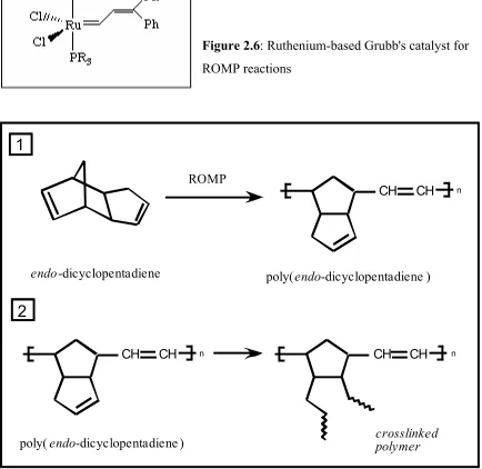
Figure 2.6: Ruthenium-based Grubb's catalyst for ROMP reactions
CH CH n
poly(endo-dicyclopentadiene ) ROMP
endo-dicyclopentadiene
1
CH CH n
poly(endo-dicyclopentadiene )
2
CH CH n
crosslinked polymer
Chemical Resistance: Bulk and Microfluidic
For bulk solvent testing, DCPD (Sigma-Aldrich 99.5 % pure) was polymerized into disks in small glass petri dishes in the presence of catalyst at a monomer/catalyst ratio of 1:12,000 (mol/mol). Just prior to the reaction, the catalyst was resuspended in a small volume (~250µl) of methylene chloride and added to the DCPD monomer. The reaction mixture was cured at 200°C for 5 minutes, consuming the catalyst while boiling off excess monomer. The final product was optically clear, extremely hard, and light amber in color. As the disks were hard to break into smaller pieces, solvent testing was carried out on whole disks of polymerized DCPD by pipetting small aliquots of solvent on the disk surfaces and looking for swelling. No swelling was observed for all n-alkanes tested, ranging from heptane to hexadecane, 10% solutions of concentrated HCl or NaOH, or alcohol solutions. Some physical swelling and darkening of the polymer surface was observed for pure toluene. Overall, the chemical resistance was in agreement with the literature.
Microfluidic solvent resistance measurements were conducted using poly-DCPD devices cast from the same type of silicon molds used for the PDMS experiments. Significant problems were encountered during device fabrication. Using 1:12,000 monomer/catalyst for the molding process on the silicon wafer, the rapid polymerization at 200°C put stress on the silicon wafer, causing it to frequently crack. This problem was remedied by lowering the catalyst/monomer ratio of the mixture from 1:24,000 to
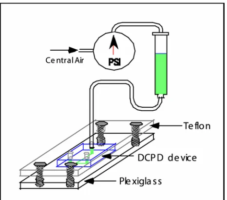
Adhesion to glass of the finished microfluidic devices was inconsistent. The softer poly-DCPD blend devices with the lower catalyst content showed initial excellent adhesion to a No. 1 coverslip. However, the softer blends contained a high percentage of uncured monomer, which boiled off at room temperature over time, causing the devices to curl and delaminate from the coverslips. To test the devices for solvent resistance, a clamping apparatus was designed that kept the microfluidic chips flat as pressurized solvent was introduced (Figure 2.8). The devices were sealed against a No. 1 coverslip and clamped between a piece of plexiglass and teflon with threaded holes for the syringe connection hardware. Nitrile O-rings were used to seal the interface between the poly-DCPD device input holes and the teflon plate when the clamping apparatus was tightened. Visualization of the flow through the plexiglass plate under a 10x objective of a light microscope (Olympus IX50) showed excellent chemical resistance (no visible swelling) for water and all n-alkane solvents tested (all linear alkanes from heptane to hexadecane) at external syringe pressures up to 15 psi. However, since physical clamping was necessary for the flow tests, delamination pressure studies could not be conducted.
Multilayer polyDCPD Devices
Attempts to fabricate multilayer polyDCPD devices were generally unsuccessful. Unlike PDMS, which contains a linear vinyl-terminated component and a crosslinking component, DCPD is its own crosslinker, which makes it difficult to create layers with different compositions for bonding. Some two-layer polyDCPD devices were constructed by adding extremely low catalyst concentrations to the monomer (<1:100,000 (w/w)), but layers for these devices either failed to cure efficiently, creating viscous partially cured mixtures, or, upon bonding, produced filled in or distorted channels due to uncured surface residue.
DCPD Co-Polymers
While microfluidic devices fabricated from pure DCPD exhibited low swelling in the presence of organic solvents, the necessity of using a clamping apparatus combined with a low resolution objective to image through the Plexiglass make the devices inefficient for sensitive screening applications. To address this issue, we produced a group of DCPD co-polymers that behaved less like duroplastics and more like elastomers.
DCPD-Cyclooctadiene (COD)
1,5-cyclooctadiene (COD) (Aldrich Chemicals) can be used in a co-polymerization reaction with DCPD to create a co-polymer that is softer and more flexible than
polyDCPD. The ROMP reaction breaks open the COD ring to produce a reactive vinyl group that crosslinks with DCPD in reaction 2 of the traditional polyDCPD mechanism, breaking up the rigid, densely crosslinked network of polyDCPD.
with the monomers at room temperature (~23°C), cure time was 85°C for 30 minutes. Complete experimental results with different co-polymer ratios are shown in Table 2.3.
Dicyclopentadiene/ 1,5-Cyclococtadiene Co-Polymers
% DCPD % 1,5-COD Ru Catalyst Ratio Product Physical Properties
80% 20% 1:6000 tough, leather-like consistency
no seal to coverslip
high DCPD odor
50% 50% 1:6000 spongy, elastomeric consistency
seals to coverslip well
some DCPD odor
40% 60% 1:6000 elastomeric consistency
seals to coverslip well
low odor
25% 75% 1:6000 very elastomeric/plastic, soft
excellent coverslip adhesion
low odor
*this blend had trouble curing
*fresh Ru catalyst essential
Table 2.3: Dicyclopentadiene/ 1,5-cyclooctadiene co-polymer study. Different ratios of DCPD and COD create co-polymers with different physical and mechanical properties.
co-polymer (vs. pure DCPD), resulting in several failed co-polymerizations due to boil off of the methylene chloride and precipitation of the ruthenium catalyst in the mixture prior to polymerization. The co-polymerizations also leave trace amounts of uncured monomer trapped in the devices, whose potent smell is an undesirable product. However, the co-polymers with a high fraction of 1,5-COD show excellent coverslip adhesion (tested up to 30 days without delamination).
Chemical Resistance: Bulk and Microfluidic
Chemical resistance of the DCPD/COD co-polymers was comparable to
polyDCPD devices. No swelling was observed for water and all alkanes (C7 - C16) in bulk tests in which solvent was pipetted on the surfaces of the co-polymers. Microfluidic tests with pressurized solvent were still difficult to conduct because we had not developed a good methodology to punch small inlet holes in the relatively tough devices. Devices cast from the silicon molds still needed to have inlet holes punched with a large diameter (~5mm) beveled steel punch, making the clamping apparatus still necessary for fluid introduction. Microfluidic solvent tests were also comparable to the results observed with polyDCPD devices. Later technological developments (see section 2.2.3-
Polyurethane-based Polymers), which used a small drill bit to make ~600 µm diameter inlet holes in tough polyurethane devices, should also work for the DCPD/COD devices, eliminating the need for a clamping apparatus to introduce fluid into the DCPD/COD microchannels.
2.2.3 Polyurethane-based Polymers
addition polymerization of a diisocyanate (whose molecules contain two –NCO groups) and a dialcohol monomer (two –OH groups). The diisocyanate and dialcohol monomers in the reaction can be long, short, aliphatic or aromatic, producing polyurethanes with a wide variety of physical and chemical properties.
C
O
N
N
C
O
O
H
CH2
CH2
O
n
H
diisocyanate
dialcohol
urethane linkage
Figure 2.9: Urethane linkage diagram formed by the addition polymerization of a diisocyanate and a dialcohol group.
Urethane Diacrylate
Urethane acrylate oligomers are high molecular weight, reactive materials that can be polymerized using several free radical mechanisms, including electron beam (EB), ultraviolet radiation (UV), peroxide decomposition or Michael Addition reaction
Figure 2.10: Urethane diacrylate oligomer. Reactive terminal vinyl groups are activated during polymerization.
Structural and Mechanical properties
As a chemically diverse group of polymers,polyurethanes synthesized from acrylated monomers vary from soft, rubbery elastomers to hard systems that resemble ceramics. Polyurethanes that are extensively cross-linked tend to be rigid and extremely tough, with Young's modulus values in the GPa range like silicon and pure polyDCPD. These hard, dense systems have very good chemical and moisture resistance. In contrast, elastomeric polyurethanes have a low degree of crosslinking. These polymers have good impact strength and flexibility, resembling silicones. However, the linear nature of the chemical bonds as an elastomer makes it more susceptible to the uptake of water and other hydrophilic compounds.
yet still behaves as an elastomer and seals exceptionally well to glass coverslips.
Microfluidic pressure tests using devices fabricated from the silicon T-channel mold (100
µm wide x 6 µm deep channels) passively sealed to glass withstood pressures up to 20 psi (dH2O) without delamination.
A UV-cure catalyst was selected for Ebecryl 270 (Irgacure 500 - Ciba Specialty Chemicals). The UV-curing process provides a rapid (<10 minutes for a 5 mm thick polymer layer), tightly controlled environment for polymerizing urethane oligomers. However, a good knowledge of the chemistry of the process is essential to understand problems such as curing failure for thin films and initial photoyellowing immediately after UV exposure.
During UV curing in air, the presence of oxygen has a detrimental effect on the cure response of free radical systems, especially for thin film coatings23. Molecular oxygen reacts with the free radicals generated during the curing process, forming peroxy radicals. The reactivity of the peroxy radicals is insufficient to drive the free radical
polymerization process to completion, resulting in chain termination and an under-cured product. This phenomenon was observed in our initial polymerization setup, which consisted of an UV light chamber (Electolite Corporation - Model ELC 500) with 4 x 9 W bulbs (365 nm). Curing in the presence of oxygen (Ebecryl 270 with 1% Irgacure catalyst (Ciba-Geigy)) resulted in a sticky, uncured film on top surface of the
polymerized urethane regardless of the exposure time (1.0-30.0 minutes) or polymer
Initial photoyellowing of UV-cured polyurethanes occurs immediately after exposure to the curing radiation. However, this initial yellowing of the polymer is partially reversible and will bleach out during the first couple of hours after exposure.
The active component of the catalyst, Irgacure 500, is an α-hydroxy alkyl acetophenone (1-hydroxycyclohexyl phenyl ketone), which can form colored yellow benzil products and other semi-quinoid structures after the radical state is generated by UV light (Figure 2.11)25. In tests with Ebecryl 270 and 1% Irgacure 500, the cured polyurethane was translucent and bright yellow in color after a 10-minute exposure in the UV light chamber. However, after the cured polymer pieces sat at room temperature for 24 hours under fluorescent lighting, no visible coloration was evident, in support of a mechanism that the colored compounds either bleach out or undergo further reactions to yield colorless products.
Chemical Resistance: Bulk and Microfluidic
Bulk tests with cured Ebecryl 270 were conducted by pipetting droplets (~30 µl) on the surface of 5 mm thick polymer sections to look for physical swelling. No swelling was observed with deionized water, alkanes (C7-C16), mineral oil, and alcohols
(isopropanol, ethanol), suggesting that the polymer would be appropriate for emulsion-based experiments. Microfluidic tests were conducted with T-channels devices cast from the silicon mold. Ebecryl 270 with 1% Irgacure 500 was poured to a depth of 5mm over the silicon mold. After curing in the ELC-500 for 10 minutes, the cured polyurethane was peeled away from the mold and the input holes were drilled at the channel ends with a
#78 drill bit at 1000 rpm (600 µm diameter). The individual devices were then cut from the mold with a razor blade and the polymer was washed with isopropanol to remove residue from the drilling process. The finished devices were then hermetically sealed to No. 1 coverslips. Pressure tests were then conducted using the same apparatus used to test the silicone devices. The noncovalent glass/polyurethane bond was much stronger than the PDMS/glass bond, delaminating at water input pressures of 12-20 psi. No swelling was observed for all alkanes (C7-C16), and their delamination pressures were comparable to water.
Multilayer Polyurethane Devices
in catalyst composition or monomer content. Activated acrylate groups at the interface efficiently initiate the crosslinking process. Using this technology, we created Ebecryl 270 microfluidic devices consisting of a thick layer (~5mm) with molded channels
bonded to a No.1 coverslip spin coated with a thin layer (~20µm) of Ebecryl 270. The two-layer device withstood pressures of 50 p.s.i. (deionized water) without delamination.
2.3
Conclusions
The key to developing functional microfluidic devices for a specific application starts with the fabrication material. Elastomers like PDMS are a good choice for
biological applications using water-based buffers. PDMS is easy to mold, cut and process into functional microfluidic devices. Its elasticity makes it ideal for fabricating multilayer microfluidic devices with integrated pumps and valves (Chapter 5). PDMS is a poor material choice for applications that use oils, alcohols, aromatics, strong acids or bases, exhibiting strong swelling in these solvents. Diene-based materials like DCPD exhibit much better solvent resistance, but are physically much harder, making it difficult to cut individual devices to size and seal them to glass substrates. Elastomeric polyurethanes, intrinsically hydrophilic, show excellent resistance to oils and can be fabricated as single layer microfluidic devices that seal strongly to glass coverslips or as multilayer
Chapter 3: Microfluidic Crossflow
Dynamic Droplet Formation Technology
3.1 Introduction
High-throughput screening (HTS) is an established technology in the
pharmaceutical industry26. Over the past decade, there has been a logarithmic increase in
the industry's ability to screen large combinatorial libraries of compounds against target
molecules27. The technology to achieve this has come in the form of robotics, high-
density microplates, small-volume (microliter) liquid handling, and sophisticated
detection schemes. Significant industrial effort has gone into the design of HTS
workstations capable of screening tens of thousands of compounds in a 24-hour period.
However, these workstations come with a large price tag, often costing several hundred
thousand to millions of dollars.
The goal to develop assay systems that are smaller, faster, and cheaper has been
realized in the field of microfluidics. Using materials such as glass, silicon, and hard
plastics such as polycarbonate, microfluidic devices have been used to demonstrate a
diverse array of biological applications, including biomolecular separations28, enzymatic
assays29, polymerase chain reaction (PCR) 30, and immunohybridization reactions31.
Capable of analyzing subnanoliter liquid volumes, these devices typically use
electroosmotic flow to manipulate liquid within the chips. Under electroosmotic flow,
carries the other solvent molecules in the same direction. While electroosmotic flow has
proved to be useful for specialized reaction conditions, it is generally inappropriate for
HTS technologies. Electroosmotic flow requires a specific ionic strength that may not be
compatible with platforms based on measuring catalytic activity or ligand-ligand binding
affinity. Additionally, the electroosmotic fluidic circuits are not generally scalable. As
channel size dimensions decrease, it becomes extremely difficult to stop flow or balance
pressure differences.
In thinking about a generic design for microfluidic HTS devices, two different
processing schemes become evident: serial and parallel. Using a serial strategy, each
compound of interest is screened sequentially using a common microfluidic channel with
a single detection element. Mechanically, throughput depends on factors such as flow
speed, sample concentration, and the acquisition time of the detector. In contrast, parallel
screening functions like an ultrahigh-density microtiter plate, in which thousands of
compounds are arrayed into individual picoliter-scale compartments, with a detector
element that probes the entire matrix. Throughput is principally limited by the number of
compartments in the array.
We designed and developed microfluidic chips employing serial and parallel
screening strategies. Unlike state-of-the-art microfluidic devices relying on
electroosmotic flow, fluidic trafficking in our chips was achieved using integrated
elastomeric valves that are scalable and whose function is independent of solvent
composition. The mechanics and theory behind the serial approach, using emulsions as
reaction vesicles, will be addressed in this chapter and the subsequent one, while
3.2 Microencapsulation
While affinity-based selection strategies have been effectively used to analyze
protein-protein binding interactions using large combinatorial protein libraries consisting
of billions of variants32,33, screening such libraries for other properties such as catalytic
activity has remained a challenge. Large mutant enzyme libraries are typically expressed
in organisms like yeast or E. coli. The screening of a large cell population of the basis of biocatalytic activity primarily involves the physical separation of the cells that allows the
assay of a single colony or cell34. Although libraries consisting of random single DNA
point mutations (6 x 10³ variants for a 300-residue enzyme) are feasibly screened through
plate assays and spectroscopic techniques, the number of variants increases exponentially
for each additional mutation, outpacing techniques which require the physical isolation of
individual mutants. The critical step in the screening process is signal development that
comes from exposing the expression host to the selected substrate. Elaborate HTS
strategies have been devised to look at enzyme libraries, such as fluorescence-activated
cell sorting (FACS) of an enzyme library tethered to the cell surface via an outer
membrane protein (OmpA) linker35. A FRET substrate is cleaved and the product
non-covalently attaches to the cell surface of the active mutants, allowing them to be sorted on
the basis of fluorescent activity. However, this technique is not generally applicable to
most enzyme systems, as most substrates either do not enter the cell or generate soluble
products that rapidly diffuse away from the cell. In such systems, compartmentalization is
needed to keep the signal associated with the cell(s) that generate it.
individual chambers using elastomeric micrarrays (Chapter 5), or a serial approach, in
which cells and substrate are encapsulated in vesicles like liposomes or reverse micelles
and sequentially analyzed like cells in a FACS machine.
Encapsulation of biological agents is not a new concept for the pharmaceutical
industry. For the past two decades, research has been carried out using liposomes as
carriers for a wide variety of drugs including anti-tumor and anti-fungal compounds as
well as genetic drugs such as antisense nucleotides and plasmids for gene therapy36.
However, liposomes are difficult to prepare, requiring organic solvents to hydrate the
dried lipid mixture and techniques such as sonication or french press to size the final
liposomes. Problems with the final product include size heterogeneity and poor aqueous
encapsulation rates, often as low as 20%37. An alternative to liposomes as encapsulation
vesicles is emulsions, consisting of water, oil and a surfactant. Depending on the relative
concentration of each component, emulsions can exist as micelles consisting of surfactant
stabilized oil droplets in an aqueous solution or as reverse micelles in which water
droplets are present in a bulk oil solution. While reverse micelles have the advantage over
liposomes of encapsulating 100% of the aqueous phase, synthesis of homogenous
emulsions has been considered a black art38. Recognizing their potential as miniature
bioreactors, we carried out fundamental research that took us from basic emulsion
formulation to the development of microfluidic devices capable of producing highly
homogenous emulsions. The description and discussion of this work are the focus of this
3.2.1 Bulk Emulsions
Fundamentals
Emulsions are metastable colloids consisting of two immiscible fluids, one
dispersed in the other, in the presence of a surfactant39. The relative ratio of the three
fractions determines the overall morphology of the surfactant phase, which can range
from oil-in-water (o/w) micelles to water-in-oil (w/o) reverse micelles with a wide range
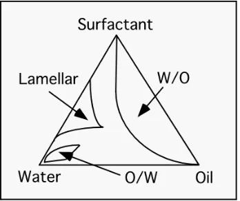
[image:51.612.108.282.269.415.2]of intermediate structures such as lamellae and cylinders (Figure 3.1). For water-in-oil
Figure 3.1: Phase diagram illustrating the relationship between the relative fractions of water/oil/surfactant and the emulsion morphology.
emulsions, the size of the reverse micelle is based on several parameters including the
type of oil and surfactant used, and temperature. Short-chain oils penetrate the surfactant
layer, increasing the spontaneous curvature of the reverse micelles and decreasing the
encapsulated aqueous phase. The limit of penetration corresponds to the length of the
surfactant molecule29. Similarly, short chain surfactant molecules form small reverse
micelles with a high spontaneous curvature. Higher temperatures lead to the formation of
larger reverse micelles when non-ionic surfactants are used. This is due to a decrease in
the size of the polar head groups as they lose ordered water molecules30.
The degradation and destruction of emulsions occur through two mechanisms.
sufficiently soluble in the continuous phase, gradually coarsening the emulsion over time.
The second mechanism, coalescence, occurs when the surfactant is depleted at the
interface between two droplets in the discontinuous phase, causing the droplets to merge.
This process is accelerated by heterogeneity in the emulsion mixture. The metastability of
an emulsion is correlated with surfactant concentration at the droplet interface.
Appro-priately formulated, emulsions can be stable for years.
Bulk Preparation - Propeller Method
The first w/o emulsion formulation experiments in the laboratory were carried out
in bulk using the propeller method of Tawfik and Griffiths38. The rationale behind their
technique was to develop a set of manufacture conditions to encapsulate combinatorial
libraries of self-encoding RNA-enzyme fusions along with substrates that could generate
fluorescent products. The substrates and protein fusion mixtures would be chilled to 4°C,
combined, and emulsified under ice cold conditions to slow down substrate catalysis
prior to encapsulation. Sorting of the enzyme containing droplets would occur by flowing
the emulsion through a microchip and sorting the droplets on the basis of fluorescent
intensity. For the emulsion optimization, the principal challenges were to create a
formulation of an oil/surfactant mixture that was not too viscous at the preparation
temperature (4°C) and to optimize the stirring conditions such that a reverse micelle
preparation was fairly homogeneous. Initial w/o emulsions were created using freshly
prepared 1 ug/ml fluorescein in 10 mM Tris-HCl pH 7.5 as the aqueous phase, a 9:1 ratio
of Span80/Tween80 as the surfactant, and one of several alkanes as the oil phase
(heptane, decane, dodecane, or light mineral oil). The oil/surfactant mixture (95% oil/ 5%
aliquots of aqueous phase were added to 1 ml of oil/surfactant stirred at 1200 rpm with a
micro magnetic stir bar over a period of 2 minutes at 4°C. The mixture was then stirred
for an additional 1 minute before being transferred to ice. Both the mineral oil and
heptane-based emulsions remained as a suspension after 15 minutes, while reverse
micelles in decane settled out and the dodecane emulsion solidified. The reverse micelles
were examined under a 40x oil immersion lens using a light microscope equipped with a
mercury lamp and green bandpass filter. Sizing of the micelles was based on a visual
comparison with 1µm diameter green latex beads mixed with the sample. All of the
preparations contained a heterogeneous size distribution of micelles, with the largest size
distribution seen in the mineral oil based preparation. The average size (diameter) for the
reverse micelles in the preparations ranged from ~0.5 µm for the hexane-based
preparation to ~5-10 µm for the mineral oil based preparation, with reverse micelles in
the decane-based preparation averaging ~2-3 µm. The size distribution was broad for all
three preparations, spanning an order of magnitude. Several large aggregates were
observed in the decane and mineral oil-based preparations (Figure 3.2).
The principal problems with the initial emulsion preparations were turbid flow
and slow propeller speed. Attempts to stir the emulsions at a faster rpm in the vials
resulted in destabilization of the magnetic stir bar and non-laminar flow. To minimize
turbulence and increase the stirring speed, a flat-bottom 24-well crystallography plate
was used. Stable stirring speeds of up to 3000 rpm were observed at room temperature
and 2500 rpm at 4°C for both heptane and decane-based emulsions. Further studies with
mineral oil were discontinued due to its high viscosity. High stirring speeds (2500 rpm,
4°C) produced a fairly homogenous preparations of reverse micelles in heptane with a
very small diameter (100 nm) and decane-based reverse micelles with a mean diameter of
1-2 µm. Stirring for longer periods of time after the aqueous addition (up to 10 minutes)
reduced the size distribution of the prepared reverse micelles. However, long term
stability of the prepared emulsions was still problematic. Coalescence of the heptane and
decane mixtures was observed within 6-12 hours, creating aggregates of small (1-2 µm)
and very large (>50 µm diameter) droplets.
Bulk Preparation - Crossflow Membrane Emulsification
Data acquired from the propeller studies suggested that emulsion stability could
be improved and that would decrease droplet heterogeneity. Studies in the early 1990s
from Japan suggested that this could be achieved through a process referred to as
crossflow membrane emulsification42,43. The concept of membrane emulsification is
simple and involves injecting the disperse phase through a porous substrate in such a way
that the droplets formed at the ends of the pores at the membrane surface are sheared off
by the continuous phase flowing normal to the membrane surface44 (Figure 3.3). This
pore size (0.5-5.25 µm) and a discontinuous oil phase sheared into a bulk water phase42.
The formed droplets were ~3.25x larger than the pore sizes with a relative standard
deviation of 10%. The problem with using glass membranes is that they are long (150
cm), cylindrical membranes used for industrial-scale production of emulsions (several
liters) and are not practical for HTS applications where microliters of reagents are
Figure 3.3: Basic stages of crossflow membrane emulsification. A) Extrusion of discontinuous phase through the pores. B) Shear of droplets at the membrane interface by the continuous phase. C) Release of monodisperse droplets into the continuous phase.
typically available. However, a good approximation of the process can be made using a
single glass capillary drawn out to a narrow (1 - 10µm) diameter. Peng and Williams
carried out such an experiment, generating monodisperse o/w droplets with diameters
ranging from 0.5 to 1.5 µm 44.
Bulk crossflow experiments were carried out in the laboratory using a
syringe-capillary hybrid device, which was used to inject the discontinuous water phase into the
oil/surfactant solution (decane, 4.5% Span 80, 0.5% Tween 20). To fabricate the syringe
a 26 3/8 G needle was forced into the capillary, expanding it. The needle capillary
junction was then sealed with epoxy. The capillary attached to the needle was drawn out
over a low gas flame to narrow its diameter. Crude estimates of final inner diameters of
capillaries drawn by this method, made by visualization under a light microscope, ranged
from 1-10 µm. The syringe-capillary apparatus was filled with water, clamped in a ring
stand, and a mass was put on the drawn plunger to generate a constant flow into the
stirring continuous phase (Figure 3.4). Flow rate was estimated by collecting droplets
Figure 3.4: Experimental setup for capillary-based crossflow (w/o) emulsification experiment. A constant mass over the syringe provides a
constant flow rate as water is introduced into the stirring continuous phase.
of water from the capillary tip prior to the emulsification process and weighing them on
a precision balance (Mettler Model AG104). For a 180 g mass, flow rate from a capillary
tip (i.d. ~5 µm) was ~1 µl/minute. The microcapillary crossflow emulsification
experiment was conducted by immersing the capillary tip in a crystallization chamber
containing 2 ml of the stirring continuous phase (decane/4.5% span 80/0.5% Tween 20,
The final emulsion was still highly polydisperse (0.5 to 10 µm diameter droplets, ave. ~ 3
µm). Problems encountered during the experiment that contributed to the polydispersity
included evaporation of the decane in the continuous phase (~25% of the total volume
over 10 minutes at 4°C) and the roughness of the capillary tip surface. Additional
experiments were conducted, including changing the stir speed of the continuous phase
(500 - 2000 rpm), rounding the tips of the drawn capillaries over gas flame, and using
parafilm to seal the continuous phase chamber during emulsification to prevent
evaporation. None of these modifications produced suitable monodisperse, stable
emulsions. Clearly, it was necessary to have much tighter control parameters to generate
monodisperse emulsions. A method was needed that provided excellent control over pore
size, contact angle, and flow rate at the shear interface. The answer was found in
microfluidics.
3.2.2 Microfluidic Crossflow
Fundamentals
Sometimes, the most beautiful experiments are the simplest ones. Microfluidic
crossflow devices spontaneously make vesicles by using two perpendicular intersecting
microchannels to shear the discontinuous phase into the continuous/ surfactant phase. The
resulting monodisperse, stable droplets are generated at a frequency controlled by the
input pressures of the two phases.
The initial designs for crossflow microfluidic devices started with the concept of
extruding water into the oil phase. Reported data from the crossflow experiments carried
out using microporous glass42,43 and single glass capillaries44 suggested that the two
discontinuous phase is introduced into the continuous phase and the contact angle of the
shear force. Transferring this technology to the microfluidic realm required extensive
design revisions, a good fabrication methodology, and optimization of the on-chip
emulsion chemistry. The documentation of this work, leading to the invention of the
microfluidic crossflow chip, will be presented in an "evolutionary" format, beginning
with the early prototypes.
Microfluidic Droplet Formation: Simple "T" channel Architecture
The first microfluidic crossflow device was designed with 50 - 100 µm wide
channels, a perpendicular junction, where the two phases are mixed, a serpentine channel
to incubate the contents of the vesicles, and a "T" junction for sorting the encapsulated
combinatorial libraries (Figure 3. 5). At the time, sorting technology in the laboratory
consisted of using electroosmotic flow to sort beads or DNA on the basis of
fluorescent intensity, which could not be applied to non-conductive (w/o) emulsions. We
envisioned monolithic valves fabricated on the microfluidic device that could be used for
droplet sorting, but my work in this area was still in its early stages.
Initial crossflow devices were fabricated from polyurethane (Ebecryl 270), which
exhibited good resistance to alkanes used in the experiments. The masks were designed
using Adobe Photoshop and printed as transparencies on Linotronic film at a resolution
of 3386 dpi. Film-based masks represent a cheap alternative (~$20) to chrome mask
designs, which cost anywhere from five hundred to thousands of dollars, depending on
the pattern size and resolution. While chrome masks can be made with sub-micron
features, this type of resolution is unnecessary for most microfluidic applications. Each
square pixel on the Linotronic mask is ~7.5µm on side, but the roughness of single pixels
on the film limit their utility as masks to 3 x 3 pixel (22.5 µm2) features.
Unlike the wet-etched silicon molds used to fabricate the polymer chemical
resistance test devices, the crossflow devices were cast from a thick photoresist (Shipley
SJR5740) that functions as the mold for the channels. SJR5740 was spin-coated on a
silicone wafer pre-treated with hexamethyldisilazane vapor (HMDS) as an adhesion
promoter at 3000 rpm for 60 seconds. The coated wafer was then soft-baked to remove
excess solvent (85°C / 60 minutes). The wafer was then patterned using the mask aligner
and developed (Microposit 2401 developer, 1:5 in dH2O). At this point in the procedure,
a positive mold of the crossflow pattern composed of photoresist is visible on the wafer
surface. The mold is then hard baked at 120°C for 20 minutes on a hotplate to round the
channels and promote their adhesion to the wafer. If the channels are not rounded,
the crosslinking process, breaking it off the wafer during the mold release. There are
other essential reasons to round the photoresist channels that will be discussed in later
sections. Two layer devices were cast from Ebecryl 270 consisting of a thick molded
layer (~5 mm) containing the channel structures and a thin layer of polyurethane
spin-coated on a No. 1 glass coverslip (~20 µm) to seal the bottom of the channels as
described in Chapter 2 (Multilayer Polyurethane Devices).
The first crossflow experiments consisted of simply shearing pressurized water
into oil at a perpendicular microfluidic junction to produce slugs of water that traveled
down the main channel to the output. While this procedure may seem counterintuitive
after the extensive discussion on emulsion stabilization, surfactant (1% Span 80 in
decane