AFIPS
CONFERENCE
PROCEEDINGS
VOLUME 35
1969
FALL JOINT
COMPUTER
CONFERENCE
The ideas and opinions expressed herein are solely those of the authors and are no necessarily representative of or endorsed by the 1969 Fall Joint Computer Conference ComInittee or the American Federation of Information Processing Societies.
Library of Congress Catalog Card Number 55-44701
AFIPS PRESS 210 Summit Avenue
Montvale, New Jersey 07645
c
1969 by the American Federation of Information Processing Societies, Montvale, New Jersey, 07645. All rights reserved. This book, or parts thereof, may not be reproduced in any form without permission of AFIPS Press.CONTENTS
OPERATING SYSTEl\1S
A survey of techniques for recognizing parallel processable stre2,ms in computer programs ...•... Performance modeling and. empirical measurements in a system
designed for batch and time-sharing users ... . Dynamic protection structures ... . The ADEPT-50 time sharing system ... .
An operational memory share supervisor providing multi-task processing within a single partition ... .
ARRAY LOGIC-LOGIC DESIGN OF THE 70's
Structured logic ... 0 • • • • •
Characters-Universal architecture for LSI ... . Fault location in cellular arrays ... ' .. Fault mUltiplication cellular arrays for LSI implementation ... . The pad relocation technique for interconnecting LSI arrays of
imperfect yield ... ' ... . COMPUTERS FOR CONGRESS
(Panel Session-No papers in this volume)
THE COMPUTER SECURITY AND PRIVACY CONTROVER.SY The application of cryptographic techniques to data processing ... . Security controls in the ADEPT-50 time-sharing system ... . Management of confidential information ... . PROGRAMMING LANGUAGES AND LANGUAGE PROCESSOR.S Some syntactic methods for specifying extendible programming
languages ... , ... . SYMPLE-A.general syntax directed macro processor ... .
An algebraic extension to LISP ... .
An on-line machine language debugger for OS/360 ... . The multics PL/1 compiler ... .
1 M. J. Gonzalez
C. V. Ramamoorthy
17 J. E. Shemer
D. W. Heying
27 B. W. Lampson
39' R. R. Linde
C. Weissman C. Fox
51
61
69
81 89
99
111
119
135
145 157
169 179
187
J. E. Braun
A. Oart~nhaus
R. A. Henle
I. T. Ho O. A. Maley R. Waxman F. D. Erwin K. J. Thurber C. V. Ramamoorthy S. C. Economides
D. F. Calhoun
R. O. Skatrud'
C. Weissman E. V. Comber
FORTHCOMING COMPUTER ARCHITECTURES
A design for a fast computer for scientific calculations ... . A display processor design ... .
The system logic and usage recorder. . . ... . Implementation of the NASA modular computer with LSI
func-tional characters ... .
DIGITAL SIMULATION OF CONTINUOUS SYSTEMS
Project DARE: Differential analyzer replacement by on-line digital simulation ... . MOBSSL-UAF: An augmented block structured continuous
sys-tems simulation language for digital and hybrid computers ... . A hybrid computer programming system ...•... Hybrid executive-User's approach ... .
PROBLEMS IN MEDICAL DATA PROCESSING
A system for clinical data management ... .
Medical education: A challenge for natural language analysis, artifical intelligence, and interactive graphics ... .
ARCHITECTURES FOR LONG TERM RELIABILITY
Design principles for processor maintainability in real-time systems .. Effects and detection of intermittent failures in digital systems .... Modular computer architecture strategies for long-term mission ... A compatible airborne multiprocessor ... .
PUBLISHING VERSUS COMPUTING (Panel Session-No papers in this volume)
INFORMATION MANAGEMENT SYSTEM,S FOR THE 70's (Panel Session-No papers in this volume)
209
219
231
247
255
275
287
297
307
319 329 337 347
P. M. M elliar-Smith R. W. Watson T. H. Myer I. E. Sutherland M. K. Vosbury
R. W. Murphy
J. J. Pariser H. E. Maurer
O. A. Korn
D. S. Miller M. J. Merritt M. A. Franklin J. C. Strauss W. L. Oraves R. A., MacDonald
R. A. Oreenes A. N. Pappalardo C. W. Marble O. O. Barnett
J. C. Weber W. D. Hagamen
H. Y. Chang J. M. Scanlon
M. Ball F. Hardie
WHAT HAPPENED TO LSI PROMISES
LSI-Past promises and present accomplishment-The dilemma of our industry ... . What has happened to LSI-A supplier's view' ... . TOPICS IN ON-LINE TECHNIQUES
Real-time graphic display of time-sharing system operating characteristics. . . .. . . A graph manipulator for on-line network picture processing ... . On-line recognition of hand generated symbols ... . MANAGING MONEY WITH ,COMPUTERS
(Panel Session-No papers in this volume)
DATA BASE AND FILE MANAGEMENT STRATEGIE.S
Common file organization techniques compared ... . An information retrieval system based on superimposed coding ... . Establishment and maintenance of a storage hierarchy for an
on-line data base \lnder TSS/360 ... . Resources management subsystem for a large corporate
informa-tion system ... .
Incorporating complex data structures in a language designed for social science research ... . CIRCUIT /MEMORY INNOVATIONS
A nanosecond threshold logic gate ... . Silicon-on-sapphire complementary MOS circuits for high speed
associative memory ... , ... . A main frame semiconductor memory for fourth generation
computers ... '. , ... .
A new approach to memory and logic-Cylindrical domain devices.
A new integrated magnetic memory ... . Mated film memory-Implementation of a new design and
production concept. . . . ••...•...
359 369
379 387
399
H. G. Rudenberg C. G. Thornton
J. M. Grochow
H. A. DiGiulio
P. L. Tuan G. M. Miller
413 N. Chapin 423 J. R. Files
H. D. Huskey
433 J. P. Considine
A. H. Weiss
441 H. Liu
W. S. Peck
P. T. Pollard
453 S.
Jr.
Kidd463
469
479
489
499
505
L. Micheel
J. R. Burns J. H. Scott
T. W. Hart,Jr D. W. Hillis J. Marley R. C. Lutz C. R. Hoffman A. H. Bobeck R. F. Fischer A. J. Perneski M. Blanchon M. Carbonel
THE IMPACT OF STANDARDIZATION FOR THE 70's
(Panel Session-No papers in this volume) USING COMPUTERS IN EDUCATION
A computer engineering laboratory ... . Evaluation of an interactive display system for teaching numerical ::.nalyBiJ.a. . . . • . . . Computer based instruction in computer programming: A symbol
manipulation-List processing approach ... .
COMPUTER RELATED SOCIAL PROBLEMS: EFFECTIVE ACTION ALTERNATIVES
(Panel Session-No papers in this volume)
DEVELOPING A SOFTWARE ENGINEERING DISCIPLINE (Panel Sossion-N 0 papers in this volume)
PROPRIETARY SOFTWARE PRODUCTS (Panel Session-:-No papers in this volume)
HARDWARE TECHNIQUES FOR INTERFACING MAN WITH THE COMPUTER
A touch sensitive X-Y position encoder for computer input ... . A queueing model for Bcan conversion ... . Charcter generation from resistive storage of time derivatives .... . Economical display generation of a large character set ... .
COMPUTER-AIDED DESIGN OF COMPUTERS
ISDS: A program that designs computer instruction sets ... . Directed library search to minimize cost ... . Computer-aIded-design for custom integrated systems ... . MANAGEMENT PROBLEMS IN HYBRID COMPUTER
FACILITIES
(Panel Session-No papers in this volume) COMPUTER OUTPUT MICROFILM SYSTEMS
An overview of the computer output microfiJm field ... . The microfilm page printer~oftware considerations ... . Computer microfilm: A cost cutting solution to the EDP output
bottleneck ... ' ... , ... .
515
525
535
D. M. Rob.inson
P. Oliver
F. P. Brooks, Jr.
P. Lorton, Jr. J. Slimick
545 A. M. Hlady
553 T. W. (lay, Jr.
561 M. L. Dertouzos
569 K. Nezu S. Naito
575 581
599
613 625
629
F. M. Haney B. A. Chubb
W. K. Orr
D. M. Avedon S. A. Brown
J. K. Koeneman
THE FUTURE IN DATA PROCESSING WITH COMMUNICATIONS
A case study of a distributed communications-oriented data processing system ... . Analysis of the communications aspects of an inquiry-response
system ... ' ... . A study of asynchronous time division multiplexing for time-sharing
computer systems ... . TOPICAL PAPERS
The jnvolved generation: Computing people and the disadvantaged . The CUE approach to problem solving ... . Self-contained exponentiation ... . DCDS digital simulating system ... .
Pattern recognition in speaker verification. . ... .
HYBRID TECHNIQUES AND APPLICATIONS
A hybrid/digital software package for the solution of chemical kinetic parameter identification problems ..•... Extended space technique for hybrid computer solution of partial
differential equations ... : . . . ... . Extension and analysis of use of derivatives for compensation of
hybrid solution of linear differential equations ... . HYPAC-A hybrid-computer circuit simulation program ... . REAL-TIME HYBRID COMPUTATIONAL SYSTEMS
A time-shared I/O processor for real-time hybrid computation ...
On-line software checkout facility for special purpose computers ... A hybrid frequency response technique and its application to
aircraft flight flutter testing ... .
637 N. Nisenoff
655 J. S. Sykes
669
679 D. B. Mayer 691 J. D. McCully 701 N~ W. Clark
W. J. Cody
707 H. Potash D. Allen S. Joseph 721 S. K. Das
W. S. Mohn
733
751
761 771
781
789
801
A. M. Carlson
D'. J. Newman J. C. Strauss
N. H. Kemp
P. Balaban
T. R. Strollo
R. S.' Tomlinson
E. R. Fiala T. H. Witzel S. S. Hughes
J. M. Simmons W. Benson
A survey of techniques for recognizing
parallel processahle streams in
computer programs
*
by C. V. RAMAMOORTHY and M. J. GONZALEZ
The University of Texas
Austin, Texas
lNTRODUCTIOK
State-of-the-art advances-in particular, anticipated advances generated by LSI-have given fresh impetus to research in the area of parallel processing. The motives for parallel processing include the following:
1. Real-time urgency. Parallel processing can increase the speed of computation beyond the limit imposed by technological limitations.
2. Reduction of turnaround· time of high priority jobs.
:~ Reduction of memory and thne requirements for "housekeeping" chores. The simultaneous but properly interlocked operations of reading inputs into memory and error checking and editing can reduce the need for large inter-mediate storages or costly transfers between members in a storage hierarchy.
4. An increase in simultaneous service to many users. In the field of the computer utility, for example, periods of peak demand are difficult to predict. The availability of spare processors enables an installation to minimize the effects of these peak periods. In addition, in the event of a system failure, faster computational speeds permit service to be provided to more users before the failure occurs.
'" This work was supported by NASA Grant NGR 44-012-144.
1
."). Improved performance in a uniprocessor
multi-progra~med environment. Even in a
unipro-cessor environment, parallel processable seg-ments of high priority jobs can be overlapped so that when one segment is waiting for I/O, the processor can be computing its companion segment. Thus an overall speed up in execution is achieved.
With reference to a single program, the term "paral-lelism" can be applied at several levels. Parallelism within a program can exist from the level of statements of procedural languages to the level of micro operations. Throughout this paper, discussion will be confined to the more general "task" parallelism. The term "task" (process) generally is intended to mean a self-contained portion of a computation which once initiated can be carried out to its completion without the need for additional inputs. Thus the term can be applied to a single statement or a group of statements.
2 Fall Joint Computer Conference, 1969
LEVEL 1 LEVEL 2 LEVEL 3 LEVEL n
Figure I-Hierarchical represen ta tion of a seq uen tially organized program
block within a level represents a single task; as before, a task can represent a statement or a group of state-ments.
Once a sequentially organized program is resolved into its various levels, a fundamental consideration of parallel processing becomes prominent-namely that of recognizing tasks within individual levels which can be executed in parallel. Assuming the existence of a system which can process independent tasks in parallel, this problem can be approached from two directions. The first approach provides the programmer with additional tools which enable him to explicitly indicate the parallel processable tasks. If it is decided to make this indication independent of the programmer, then it is necessary to recognize. the parallel processable tasks implicitly by analysis of the relationship between tasks within the source program.
After the information is obtained by either of these approaches, it must still be communicated to and utilized by the operating system. At this point, efficient resource utilization becomes the prime consideration. The conditions which determine whether or not two tasks can be executed in parallel have been investi-gated by Bernstein.1 Consider several tasks, T i, of a
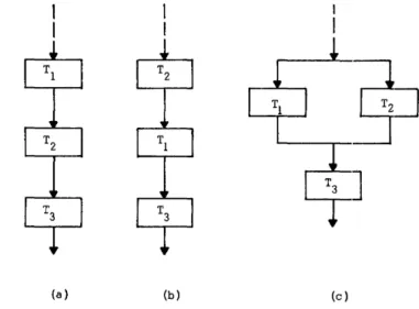
sequentially organized program illustrated by a flow chart as shown in Figure 2(a). If the execution of
(a) (b) (c)
Figure 2-Sequential and parallel execution of a computational process
task Ts is independent of whether tasks Tl and T2 are executed sequentially as shown in Figure 2(a) or 2(b), then parallelism is said to exist between tasks T 1 and
T2. They can, therefore, be executed in parallel as shown in Figure 2(c).
This "commutativity" is a necessary but IlLOt suffi-cient condition for parallel processing. There may exist, for instance, two processes which can be exelcuted in either order but not in parallel. For example:, the in-verse of a matrix A can be obtained in either of the two ways shown below.
(1)
a) Obtain transpose of A
b) Obtain matrix of co-factors of the transposed matrix
c) Divide result by determinant of A
(2)
a) Obtain matrix of cofactors of A
b) Transpose matrix of cofactors c) Divide result by
determinu.nt of A Thus obtaining the matrix of cofactors and the trans-position operation are two distinct processes which can be executed in alternate order with the same result. They cannot, however, be executed in parallel.
Other complications may arise due to hardware limitations. Two tasks, for example, may need to access the same memory. In this and similar situations, requests for service must be queued. Djkstra, Knuth, and Coffman2 •8 •4 have developed efficient scheduling procedures for using common resources.
Techniques for Recognizing Parallel Processable Streams 3
satisfied before sequentially organized processes can be executed in parallel. These are based on four separate ways in which a sequence of instruct'ions can use a memory location:
(1) The location is only fetched during the execution ofTi .
(2) The location is only stored during the execution ofTi •
(3) The first operation within a task involves a fetch with respect to a location; one of the succeeding oper-ations of T i stores in this location.
(4) The first operation within a task involves a store with respect to a location; one of the succeeding oper-ations of T i fetches this location.
Assuming a machine model in which processors are allowed to communicate directly with the memory and multi-access operations are permitted, the con-ditions for strictly parallel execution of two tasks or program blocks can be stated as fo11ows.
(1) The areas of memory which Task 1 "reads" and onto which Task 2 "writes" should be mutually exclusive, and vice-versa.
(2) With respect to the next task in a sequential process, Tasks 1 and 2 should not store information in
a common location.
The conditions listed by Bernstein are sufficient to guarantee commutativity and parallelism of two program blocks. He has shown, however, that there do not exist algorithms for deciding the commutativity or parallelism of arbitrary program blocks.
As an example of what has been discussed here consider the tasks shown below \vhich represent FOR-TRAN statements for evaluation of three arithmetic expressions.
x
= (A+B)*
(A-B)Y = (C-D) / (C+D)
z
=
X+y
Because the execution of the third expression is inde-pendent of the order in which the first two expressions are executed, the first two expressions can be executed in parallel.
Parallelism within a task can also exist when indi-vidual components of compound tasks can be executed concurrently. In the same manner that ind.ividual processors can be assigned to independent tasks,
individual functional units can be assigned to inde-pendent components within a task. The motivation remains the same-- a decrease in execution time of indjvidual tasks. The CDC 6600, for example, can utilize several arithmetic units to perform several operations simultaneously. This type of parallelism can be illustrated by the arithmetic expression which follows.
x
=
(A+B)*
(C-D)Normally, this expression would be evaluated in a manner similar to that shown in Figure 3(a). The independent components within the expression, how-ever, permit parallel execution as shown in Figure 3(b) with the same results.
Explidt and implicit parallelsim
In the explicit approach to parallelism, the program-mer himself indicates the tasks within a computational process which can be executed in parallel. This is normally done by means of additional instructions in the programming language. This approach can be illustrated by the techniques described by Conway, Opler, Gosden, and others5 ,6,7. FORK in the FORK and JOIN technique6 indicates thep arallel process-ability of a specified set of tasks,within a process. The next sequence of tasks will not be initiated until all
(a) (b)
4 Fall Joint Computer Conference, 1969
the tasks emanating from a FORK converge to a JOIN statement.
In some instances, some of the parallel operations initiated by the FORK instruction do not have to be completed before processing can continue. For example, one of these branch operations may be designed to alert an I/O unit to the fact that it is to be used mo-mentarily. The conventional FORK must be modified to take care of these situations. Execution of an IDLE
Figure 4-FORK and JOIN technique
statement, for example, permits proceSSOrB to be released without initiation of further action.7 The FORK and .JOIN TECHNIQUE is illust:rated in Figure 4.
Another example of the explicit approach is the PARALLEL FOR7 which takes advantage of parallel operations generated by the FOR statement in ALGOL and similar constructs in other languages. For example, the sum of two n X n matrices consists essentially of n2 independent operations. If n processors were availa-ble, the addition process could be organized such that entire rows or columns could be added simultaneously. Thus the addition of the two matrices could he accom-plished in n units of time. Another example of this approach is the programming language PL/l which provides the TASK option with the CALL staten;.ent which indicates concurrent execution of parallel tasks.
An additional way of indicating parallelism explicitly is to write a language which exploits the parallelism in algorithms to be implemented by the operating system. This is the case with TRANQUIL,8,21 an ALGOL-like language to be utilized by the array processors of the ILLIAC IV. The situation is unique in that the language was created after a system was devised to solve an existing problem. "The task of compiling a language for the ILLIAC IV is more difficult than compiling for conventional machines simply because of the different hardware organization and the need to utilize its parallelism efficiently." A limitation of this app:roach is that programs written in that particular language can only be run on array-type computers and is, therefore, heavily machine dependent.
The implicit approach to parallelism does not depend on the programmer for determination of inherent parallelism but relies instead on indicators existing within the program itself. In contrast to the relative ease of implementation of explicit parallelism, the implicit approach is associated with complex compiling and supervisory programs.
The detection of inherent parallelism between a set of tasks depends on thorough analysis of the source pro,gram using Bernstein's conditions. Implementati.on of a recognition scheme to accomplish this detecti.on is dependent on the source langua,ge. Thus a r€lco:~nizer
which is universally applicable cannot be implomented. An algorithm developed by Fisher9 approaches the
Techniques for Recognizing ParaUelProcessable Stream.s 5
ordering among the processes, and any initially known essential order among the processes, the algorithm generates the essential serial ordering relation and the covering for the essential serial ordering relation. This covering provides an indication of the tasks within the overall process which can be executed concurrently. Basically, this work formalizes in the form of an algorithm the conditions for par2Jlel processing devel-oped by Bernstein. The conditions for parallel processing between two tasks are extended to an overall process
Detection of task paraUelism-A new approach
,The next subject covered in this paper involves implicit detection of parallel processable tasks within programs prepared. for serial execution. An indication is desired of the tasks which can be executed in parallel and the tasks which must be completed before the start of the next sequence of tasks. Thus the problem can be broken down in two parts-recognizing the relationships between tasks within a level and using this information to indicate the ordering between tasks. The approach presented here is based on the fact that computational processes can be modeled by oriented graphs in which the vertices (nodes) represent single tasks and the oriented edges (directed branches) represent the permissible transition to the next task in sequence. The graph (and thus the computational process) can be represented in a computer by means of a Connectivity Matrix, C.IO.ll C is of dimension n X n such . that Ci j is a "1" if and only if there is a
directed edge from node i to node j, and it is "0" otherwise. The properties of the directed graph and hence of the computational process it represents can be studied by simple manipulations of the connectivity matrix.
A graph consisting of a set of vertices is said to be
strongly connected if and only if any node in it is reach-able from any other. A subgraph of any graph is defined as consisting of a subset of vertices with all the edges between them retained. A maximal strongly connected
(l\!£.S.C.) subgraph is a strongly connected subgraph that includes all possible nodes which are strongly connected with each other. Given a connectivity matrix of a graph, all its M.S.C. subgraphs can be determined simply by well-known methods.to A given program graph can be reduced by replacing each of its M.S.C. sub graphs by a single vertex and retaining the edges . connected . betwe~n these vertices and others. After the reduction, the reduced graph will not contain any
strongly connected components.
The paragraphs which follow will describe the se-quence of operations needed to prepare for parallel
processing in a multiprocessor computer a program written for a uniprocessor machine.
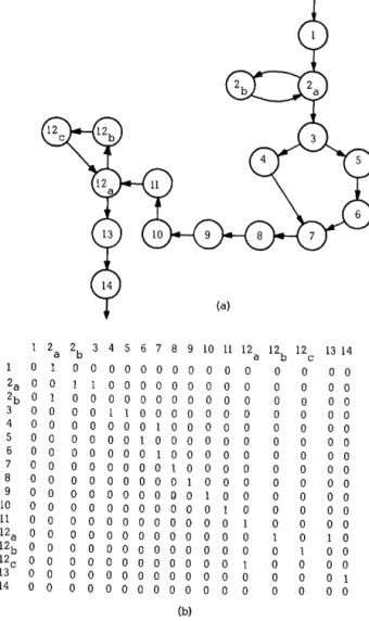
(1) The first step is to derive the program graph
which identifies the sequence in which the computation al tasks are performed in the sequentially code-program. Figure 5(a) illustrates an example program graph. The program graph is represented in the com-puter by its connectivity matrix. The connectivity matrix for the example is given in Figure 5(b).
(2) By an analysis of the connectivity matrix, the maximal strongly connected subgraphs are determined by simple operations.1O This type of subgraph is i:l-lustrated by tasks 2 and 12 in Figure .5. Each M.S.C. subgraph is next considered as a single task, and the graph, called the reduced graph, is derived. The re-duced graph does not contain any loops or strongly
1 2 a 2b 3 4 5 6 7 8 9 10 11 12 a 12b 12 13 14 c
0 1 0 0 o 0 0 0 0 0 0 0 0 0 0 0 0
2a 0 0 1 1 o 0 o 0 o 0 0 0 0 0 0 0 0
2b 0 1 0 0 0 0 0 0 0 0 0 0 0 0 0 0 0
3 0 0 0 0 1 1 o 0 0 0 0 0 0 0 0 0 0
4 0 0 0 0 0 0 0 1 0 0 0 0 0 0 0 0 0
5 0 0 0 0 0 0 1 0 0 0 0 0 0 0 0 0 0
6 0 0 0 0 0 0 0 1 o 0 0 0 0 0 0 0 0
7 0 0 0 0 0 0 0 0 1 0 0 0 0 0 0 0 0
8 0 0 0 0 0 0 0 0 0 1 0 0 0 0 0 0 0
9 0 0 0 0 0 0 0 0 0 0 1 0 0 0 0 0 0
10 0 0 0 0 0 0 0 0 0 0 0 1 0 0 0 0 0
11 0 0 0 0 0 0 0 0 0 0 0 0 1 0 0 0 0
12a 0 0 0 0 0 0 0 0 0 0 0 0 0 1 0 1 0
12b 0 0 0 0 0 0 0 0 0 0 0 0 0 0 1 0 0
12c 0 0 0 0 0 0 0 0 0 0 0 0 1 0 0 0 0
13 0 0 0 0 0 0 0 0 0 0 0 0 0 0 0 0 1
14 0 0 0 0 0 0 0 0 0 0 0 0 0 0 0 0 0
(b)
6 Fall Joint Computer Conference, 1969
connected elements. In this graph; when two or more edges emanate from a vertex, a conditional branching is indicated. That is, the execution sequence
",-m
take only one of the indicated alternatives. A vertex which initiates the branching operation wdl be called adecision or branch vertex. The reduced graph for the example program graph is shown in Figure 6. In this graph. vertex 3 represents a branch vertex.
(3) The next step is to derive the final program graph and its connectivity matrix T. The elements of
T are obtained by analyzing the inputs of each vertex
in the reduced graph. An element, Tii , iF! a "I" if
and only if the j-th task (vertex) of the reduced graph has as one of its inputs the output of task i; othCf\vise T ii is a "0". Figure 7 illustrates the final program for the example after consideration iR given to the input-output relationships of each taRk. The connectivity matrix for the final program gr9ph is shown in F"gure R.
From the sufficiency conditions for task parallelism. two tasks can be executed in parallel if the input set of one task does not depend on the output Ret of the other and vice versa. The technique outlined in Step 4 detects this relationship and uses it to provide an ordering for task execution.
(4) The vertices of the final program graph are
F!gure 6--Reduced program graph of the serially coded program
1=
,
E) 6
= f{S).4 a 9 10 11 12 13 14
Figure 7-Final progra:n graph of the parallel
0 0 0 0 0 0 0 0 0 0 0 processable i)rogram
0 0 0
0 0 0
0 0
0
0 0
0 0 0
0
0 0 0
0 0 0
0 Precedence Partitlons 0 0 0 0 0 0 0 0 0 0
10 11
0 0 0
0 0 0
0 0 0 0 0
0 0 0 0 0
0 0 0 0
0 0 0 0
0 0 0 0
0 0
0 0 0 0
0 0 0 0
0 0 0 0 0
0 0
0 0 0 0
0 0 0 0 0
[I} , (2} , {3,a} , (4,5,9,lO}
(6,11,12}, (7,131, (141 1" 0 0 0 0 0 0 0 0
Figure 8-Connectivity matrix of the final program graph
13 14
0 0
0 0
0 0
0
0 0
0 0
0
0 0
0
0
0
0
partitioned into "precedence partitions"P as follows. Using the connectivity matrix T, a column (or columns) containing only zeroes is located. Let this eolumn correspond to vertex Vl. Next delete from T both the column and the row corresponding to this vertex. The first precedence partiton is P 1
=
{vI} . Using there-maining portion of T, locate vertices {V21, Vzz, . .. } which correspond to columns containing only zeroes. The second precedence partition Pz thus contains vertices
Techniques for Recognizing Parallel Processable Streams 7
{V21, V22, ••• } can be initiated and executed in parallel
after the tasks in the previous partition (i.e., PI) have been completed. Next delete from T the columns and rows corresponding to vertices in P2• This procedure is repeated to obtain precedence partitions Pa,P4,' .. Pp , until no more columns or rows remain in the T matrix.
It can be shown that this partitioning procedure is valid for connectivity matrices of graphs which contain no strongly connected components.
The implication of this precedence partitioning is that if P1,P2, ••• P p corresponds to times t1,t2,. • •
t
p , theearliest time that a task in partition Pi can be initiated is
ti.
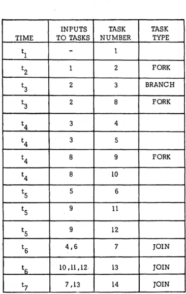
The final program graph contains the following types of vertices: (1) The branch or decision type vertex from which the execution sequence selects a task from a set of alternative tasks. (2) The Fork vertex which can initiate a set of parallel tasks. (3) The Join vertex to which a set of parallel tasks converge after their execution .• (4) The normal vertex which receives its input set from the outputs of preceding tasks. Figure 7a indicates the final program graph with the first three types of vertices indicated by B, F, and J, respectively. (5) From precedence partitioning and the final program graph, a Task Scheduling Table can be developed. This table, shown in Table I, serves as an input to the operating system to help in the scheduling of tasks. For example, if the task being executed is a Fork task, a look-ahead feature of the system can prepare for parallel execution of the tasks to be ini-tated upon compl~tion of the currently active task.
(6) The precedence partitions of Step 4 provide an indication of the earliest time at which a task may be
initiated. It is also desirable, however, to provide an indication of the latest time at which a task may be
initiated. This information can be obtained by per-forming precedence partitions on the transpose of the
T matrix. This process can be referred to as "row par-titions". The implication here is that if task is in the partition corresponding to time period h, then h is the latest time that the task i can be initiated.
Using both the row and column partitions, the per-missible initiation time for each task can be derived as shown in Table II. Task 4, for example, can be in-itiated during t4 or to depending on the availability of processors.
At this point it is desirable to clarify some possible misinterpretations of the implications of this method. The method presented here does not try to determine whether any or· all of the iterations within a loop can be executed simultaneously. Rather the iterations executed sequentially are considered as a single task.
TABLE I-Tp.sk scheduling table
INPUTS TASK TASK
TIME TO TASKS NUMBER TYPE
tl
-
1t2 1 2 FORK
t3 2 3 BRANCH
t3 2 8 FORK
t4 3 4
t4 3 5
t4 8 9 FORK
t4 8 10
ts 5 6
ts 9 11
ts 9 12
t6 4,6 7 JOIN
to 10,11,12· 13 JOIN
t7 7 ,13 14 JOIN
For this reason, the undecidability problem introduced by Bernstein is not a factor here.
In addition, precedence partitions may place the successors of a conditional within the same partition. The interpretation of this is that only one of the suc-cessots will be executed, and it can be executed in parallel with .the other tasks within that partition.
The FORTRAN parallel task recognizer
In order to determine the degree of applicability of the method described above, it was decided to apply the method to a sample FORTRAN program. This was accomplished by writing a program whose input consists of a FORTRAN source program; its output consists of a listing of the tasks within the first level
8 Fall Joint Computer Cqnference, 1969
TABLE II-Permissible task initiation time
COLUMN PARTITIONS PERMISSIBLE TASK
TIME TASK INITIATION PERIODS
t1 1 TASK TIME
t? 2 1 t1
t3 3,8 2 t2
t4 4,S,9,1O 3 t3
ts 6,11,12 4 t4, ts
t6 7 ,13 S t4
t7 14 6 ts
ROW PARTITIONS 7 t6
t1 1 8, t3
t2 2 9 t4
t3 3,8 10 t 4 , ts
t4 S,9 11 ts
ts 4,6,10 ,11,1:1 12 ts
t6 7 ,13 13 t6
t7 14 1~ t7
detection is known in its final form as a FORTRAN Parallel Task Recognizer .13
The recognizer, also written in FORTRAN, relies on indicators generated by the; way in which the program is actually written. ConSider the expressions given below.
Xl = f1(A,B) X2 = f2(C,D)
Because the right-hand side of the second expression does not contain a parameter gen~rated by the compu-tation which immediately preced~s it, the two expres-sions can be executed in parallel. ~f, on the other hand, the expressions were rewritten as shown below, the
termination of the first computation would have to precede the initiation of the second.
Xl = fl(A,B) X2 = f2(XI,C)
The recognizer performs this determination by com-paring the parameters on the right-hand of the equality sign to outcomes generated by previous statements. Other FORTRAN instructions can be analyzed similarly. Consider the arithmetic IF:
IF (X - Y) 3,4,5
Here the parameters within the parentheses must be compared to the outputs of preceding statements in order to determine essential order.
Other FORTRAN instructions are analyzed in a similar manner in order to generate the connectivity matrix for the source program. During t.b.is analysis the recognizer assigns numbers to the executable statements of the source program. After this is com-pleted, the recognizer proceeds with the method of precedence partitions described earlier. Precedence partitions yield a list of blocks which contain the state-ment numbers which can be executed concurrently,
Figure 9 shows a block diagram of the steps t:a.ken by the recognizer to generate the parallel processable tasks within the first level of a FORTRAN source program.
Some statements within the FORTRAN set are treated somewhat differently. The DO statement, for example, does not itself contain any input or output parameters but instead generates a series of repeated operations. Because of the loop considerations men-tioned earlier, and because the rules of FOHTRAN require entrance into a loop only through the DO statement, all the statements contained within a DO loop are considered as a single task. A loop, however, may contain a large number of statements, and a great amount of potential parallelism may be lost if con-sideration is not given to the statements within the loop. For this reason, the recognizer generates a sepa-rate connectivity matrix for each DO loop within the program.
Techniques for Recognizing Parallel Processable Streams 9
SCAN EXECUTABLE STATEMENTS AND COMPARE INPUT PARAMETERS TO OUTPU1S a' FRLVlCUS STATEMENTS
HEN MATCH IS FOUND ,MJKE ENI'RY IN C,i.e. , SHOW A CONNECTION FROM PREDECESSOR TO SUCCESSOR
AFTER GENERATION OF CIS CCMPLETE, GEm:RATE
PRECEDENCE PARTITIONS
N
READ NEXT SOURCE PROGRAM IN3'1RUCTION
IF THIS TAS< IS THE SUCCESSOR OF A BRANCH OR TRAN3HR CPERJU'ION, REOORD THIS I!'lFffiMATION
ECORDINPUT ND OUTPUT >-_"":_'1ARAME TERS
QUIRED BY HIS TASK
USING THE As)IGNED STATEMENT NUMBERS INDICATE THOSE
I---I~TASKS WI'lHIN THE FIRST LEVEL WHICH CAN BE DONE IN PARALLEL
Figure 9-Block diagram of the FORTRAN parallel te.sk recognizer
created by branch and transfer operations such as the IF and GO TO instructions. To eliminate these loops, it would be necessary to analyze the connectiv-ity matrix in the manner mentioned earlier before beginning the process of precedence partitions. The recognizer does not presently perform this analysis. Nested DO loops are not permitted, and the source program size is limited in the number of executable statements it may have and in the number of param-eters anyone statement can contain.
Some of these limitations could be eliminated quite easily; others would require a considerable amount of effort. To allow a source program of arbitrary size would require a somewhat more elaborate handling of memory requirements and associated problems. At the
C C 9 10 11 12 13 14 15 16 17 18 19 20 21 20 10 30 40 50 60 100 200 3057 315 4 52
THIS IS A TEST PROGRAM DESIGNED TO CHECK PPS DIMENSION Al(lO) ,A2(l0) ,A3(l0)
INTEGER Al ,A2 ,ABC ,A2X2, B ,C ,D READ 100, (Al(I) ,1=1 ,10), B ,C ,D READ 100, (A2(I),I=1,10),NS,NST,NSTU DO 10 1=1,10
IF (Al(I) -A2(I)) 20,30,40 Xl=(Al(I))*(B-C)
X2=D+(B/c)
A3(I)=Xl*X2 CONTINUE
THIS IS A TEST COMMENT PRINT 200 ,B,C ,D
CALL ALPHA(Al ,A2 ,ABC, B4 ,B5) PRINT 3057 ,Xl ,X2, (A3(I) ,1=1 ,10) CALL BETA(Xl ,X2 ,A3, B6) IF(B4-B5) 50.50,60 READ 315, E , F • G • H X3=(E*F)+(G-H) X4=B6+G X5=X3-X4 X6=(B4+B5)* X5 PRINT 4,X3,X4,X5
PRINT 52, (Al(I) , 1=1,10) .ABC ,C, (A3(I) ,1=1.10) FORMAT(lOI2,3I3)
FORMAT(1HO,8 B C D* ,/,313) FORMAT(1H ,213 .lOF7 .1) FORMAT(4F7 • 4) FORMAT(3F7 • 4) FORMAT(12I3 ,10F7 .1) END (a) PAR}\LLEL PROCESSABLE TASKS (1,2) (3) (9,10.11,12) (13) (14) (15,16) (17) (18.19,20) (b)
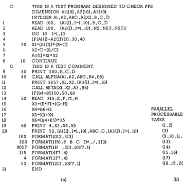
Figure IO-An exe.mple of the recognition process.
present time the recognizer consists of a main program and six subroutines. In its present form the recognizer consists of approximately 1300 statements.
The recognizer is presently written in such a manner that it will detect only first level parallelism. The method it uses, however, can be applied to parallelism at any level.
The theory of operation of the FORTRAN parallel task recognizer will be illustrated by applying the recognition techniques to a sample FORTRAN program. Figure IOCa) is a listing of the sample program showing the individual tasks. Figure IOCb) is a listing of the parallel processable tasks as determined by precedence partitions. The numbers to the left of the executable statements are the numbers assigned by the recognizer during the recognition phase.
Elimination of the limitations mentioned here and other limitations not mentioned explicitly will be the subject of future effort.
Observations and comments
10 Fall Joint Computer Conference, 1969
FORTRAN recognizer, for example, may determine that two subroutines can be executed in parallel. At the present time no consideration is given to the fact that both subroutines may access common data through COMMON or EQUIVALENCE statements. In order to truly optimize execution time for a program which is set up for parallel process'llg, it would be highly desirable to determine the time re-quired for execution of the individual tasks ·within the process. It is not enough to merely determine that two tasks can be executed concurrently; the primary goal is that this parallel execution result in higher resource utilization and improved throughput. If the time required for the execution of one task is 100 tImes that of the other, for example, then it may be desirable to execute the two tasks serially rather than in parallel. The reasoning here is that no time wou~d be spent in allocating processors and so forth.
Determinat;.on of task execution time, however, is not a simple matter. Exhaustive measurements of the type suggested by Russell and Estrin14 would provide the type of information mentioned here.
Another problem area involves implementation of special purpose languages such as TRANQUIL. It was mentioned earlier that programs written in a language of this type are highly machine-limited. It would be highly desirable to be able to implement progr9ms written in these languages in systems whicl~
are not designed to take advantage of parallelism. Along these lines, the programming generality sug-gested by Dennis15 may be significant.
It should be pointed out that aU the techniques whl.ch have been discussed here will create a certain amount of overhead. For this reason it is felt that a parallel task recognizer, for example, would be best suited for implementation with production programs. Thus even though some time would be lost initially, in the long run parallel processing would result in a significant net gain.
Conclusions
The method of indicating parallel processable tasks introduced here and illustrated in part by the FOR-TRAN Parallel Recognizer appears to provide enough generality that it is independent of the language, the application, the mode of compilation, and the number of processors in the system. It is anticipated that this method will remain as the basis for further effort in this area.
In additi.on to the comments made earlier, some possible future areas of effort include determination of
possible paralleljsm of individual iterations within a loop. It is hoped that additional information can be provided to the operating system other than a mere indication of the tasks which can be executed in paral-lel. This would include the measurements mentioned earlier and an indication of the frequency of execution of individual tasks.
I t is also hoped that a sub-language may be de-veloped which can be added to existing languages to assist in the recognition process and the development of recognizer code.
Detection of parallel components within compound tasks
Several algorithms exist for the detection of inde-pendent components within compound tasks.16.17.1b.19 These algorithms are concerned pr·.marily with de-tection of this type of parallelism within arithmetic expressions. The first three algorithms referenced above are summarized in [19] where a new all~orithm
js also introduced.
The arithmetic expression which will be used as an example for each algorithm is given below.
A+B+C+D*E*F+G+H
Throughout this discussion. the usual precedence between operators will apply. In order of increasing precedence, the precedence between operators will be as follows: + and - , * and/, and
t,
wherel'
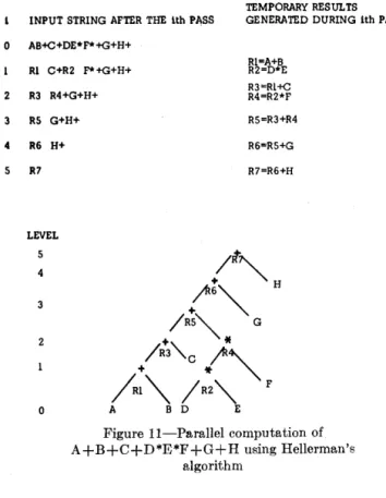
stands for exponentiation.Hellerman's algorithm
This algorithm assumes that the input string is written in reverse Polish notation and contailns only binary operators. The string is scanned from left to right replacing by temporary results each occmrrence of adjacent operands immediately followed by an operator. These temporary results will be considered as operands during the next passes. Temporary results generated during a given pass are said to be at the same level and therefore can be executed in parallel. There will be as many passes as there are levels in the
~;;yntactic tree. The compilation of the expression
listed above is shown in Figure 11.
0
2
4
5
Techniques for Re,cognizing Parallel Processable Streams 11
TEMPORARY RESULTS INPUT STRING AFTER THE lth PI\SS GENERATED DURING lth PASS
AB+C+DE*F* +G+H+
Rl=A+B Rl C+R2 F*+G+H+ R2=D*E
R3=Rl+C R3 R4+G+H+ R4=R2*F
RS G+H+ RS=R3+R4
R6 H+
R7
LEVEL
5
4
o
R6=RS+G
R7=R6+H
~~
It""
H/RS""" G
A"-c
1',\
;I.;", /
R: '" F
A B D E
Figure ll-Parallel computation of A+B+C+D*E*F+G+H using Hellerman's
algorithm
Stone's algorithm
The basic function of this algorithm is to combine two subtrees of the same level into a level that is one higher. For example, A and B, initially of level 0, are combined to form a subtree of level 1. The algorithm then searches for another subtree of level 1 byattempt-ing to combine C and D. Since precedence relation-ships between operators prohibit this combination, the level of subtree (A+B) is incremented by one. The algorithm now searches for a subtree of level 2 by attempting to combine C, D, and E. Since this com-bination is also prohibited, 'subtree (A+B) is incre-mented to level 3. The next search is successful, and a subtree of level 3 is obtained by combining C, D, E and F. These two subtrees are then combined to form a single subtree of level 4 .
In a similar manner the subtree (G+H), originally of level 1, is successively incremented until it achieves a level of 4; at that time it is combined with the other subtree of the same level to form a final tree of level 5. The algorithm yields an output string in reverse Polish which does not expressly show which operations can be performed in parallel. Even though the output string is generated in one pass, the recursiveness of
the algorithm causes it to be slow, and at least one additional pass would be required to specify parallel computations.
Squire's algorithm
The goal of this algorithm is to form quintuples of temporary results of the form:
Ri (operand 1, operator, operand 2, start level
= max [end level op. 1; end level op. 2], end level= start level + 1) .
All temporary results which have the same start level can be computed in parallel. Initially, all variables have a start and end level equal to zero.
Scanning begins with the rightmost operator of the input string and proceeds from right to left until an operator is fouIld whose priority is lower than that of the previously scanned operator. In the example thp scan would yield the following substring:
D*E*F+G+H
N ow a left to right scan proceeds until an operator is found whose priority is lower than that of the left-most operator of the substring. This yields: D*E*F. At this point a temporary result Rl is available of the form:
HI (D, *,E,O,I).
The temporary result, Rl, replaces one of the operands and the other is deleted together with its left operator The new substring is then:
R1*F+G+H.
The left to right scans are repeated until no further qunituple can be produced, and at that time, the right to left scan is re-initiated. The results of the process are shown in Figure 12.
Although the example shm,'s the algorithm applied to an expression containing only binary operators, the algorithm can also handle subtraction and division with a corresponding increase in complexity.
12 Fall Joint Computer Conference, 1969
INITIAL STRING: A+B+C+D*E*F+ G+H
RIGHT TO LEFT SCAN LEFT TO RIGHT SCAN
D*E*F+G+H Rl*F+G+H
R2+G+H
A+B+C+R2+G+H R3+C+R2+G+H
R4+R3+R2+H R4+RS+R2 R6+R2 R7
QUINTUPLES Op.l OPERATOR Op.2 START
Rl D E 0
R2 F Rl 1
R3 A + B 0
R4 C + G 0
RS H + R3 1
R6 R4 + RS 2
R7 R2 + .R6 3
LEVEL
4
3
o
Figure 12-Parallel computation of A+B+C+D*E*F+G+H uE-ing Squire's p,lgorithm
Baer and Bovet's algorithm
END
J
2
1 1
2 3 4
The algorhhm uses mUltiple passes. To each pass corresponds a level. All temporary results which can be generated at that level are constructed and inserted appropriately in the output string produced by the corresponding pass. Then, this output string becomes the input string for the next level until the whole expression has been compiled. Thus the number of passes will be equal to the nUInber of levels in the syntactic tree. During a pass the scanning proceeds from left to right and each operator and operand is scanned only once.
The simple intermediate language which this al-gorithm produces is the most appropriate for multi-processor compilation in that it shows directly all operations which can be performed in parallel, namely those having the same level number. The syntactic tree generated by this algorithm is shown in Figure
13.
A new algorithm
This section will introduce a technique whose goals are: (1) to produce a binary tree which illustrates the parallelism inherent in an arithmetic expression; and
LEVEL
4
3
2
1
o
Figure 13-Parallel computation of A+B+C+D*E*F+G+H using Baer and
Bovet's algorithm
(2) to determine the number of registers needed to evaluate large arithmetic or Boolean expressions with-out intermediate transfers to main memory.
This technique is prompted by the fact that existing computing systems possess multiple arithmetic units which can contain a large number of active storages (registers). In addition, the superior memory band-widths of the next generation of computers will simplify some of the requirements of this technique.
In the material presented below, a complex arithmet-ic expression· is examined to determine its maximum computational parallelism. This is accomplished by repeated rearrangement of the given expression. During this process the given expression in reverse Polish form is also tested for "well formation", i.e., errors and oversights in the syntax, etc.
The arithmetic expression which was used aB a model earlier will also be used here, namely A+B+C+D *E*F+G+H. The details of the algorithm follow:
(1) The first step is to rewrite the expression in reverse Polish form and to reverse its order.
+H+G+*F*E D+C+B+A
Techniques for Recognizing Parallel Processable Streams 13
Assign to symbol Si the value Vi = (V i-I) + Ri
i = 1,2, ... ,n
where Ri = 1 - O(Si) given that O(Si) = 0 if Sds a variable O(Si)
=
1 if Si is a unary operatorO(Si) = 2 if Si is a binary operator
and V i - l = V i-2+Ri - 1, V i-2 =, V i-3 + Hi- 2,
etc.,
such that V i-(i-l) = VI = HI. and \'0 = 0 Using this procedure, the following expression results:
Root Xode
8
14 13 12 11 10Si H + G +
*
Vi 2 1 2 2
Vm 9 8
8
6 5 4 3 2 1F
*
D + C + B A3 2 2 1 2 2 1
Note that for a "well-formed expression" of n symbols V1l = 1.
(3) At this point the root node of the proposed binary tree can be determined. Thus the given string can be divided into two independent sub-strings. To determine the root node, draw a line to the left of the firRt symbol with a weight of 1 (i = 11, Si=+, Vi=l)
to the left of the symbol with the highest weight, Vm(i=7, Si=E, Vi=Vm=3). The two independent substrings consist of the strings to the left and to the right of this line. The root node will be the leftmost member of the string to the left of the line (i= 15, St=+, Vi=l). Note that Vi also equals 3 for j=9; however V m is chosen from the etuliest occurrence of a symbol with the highest weight.
(4) The next step is to look for parallelism withni each of the new substrings. Consider the rightmost substring. Form a new substring consisting of the symbols within the values of Vi = 1 to the right and to the left of V m' Transpose this substring with the
sub-string to the right of it whose leftmost member has a weight of V i= 1.
INITIALRIGHTMOSTSi
+
*F*ED+C+BASUBSTRING ViI 2 3 2 3 2 1 2 1 2 1
---.
.--FINAL RIGHTMOST 11 10 9 8 7 6543 2 1 SUBSTRING Si + + C + B A * F * E D
Vi 12 3 1321212 1
This procedure is repeated until the initia,l V m occupies the position i = 2 in the substring. For this example this is already the case. Thus the rightmost substring is in the proper form.
(5) The transposition procedure of step 4 is applied next to the leftmost substring. However, since the leftmost substring of this example consists of only two operands and one operator, no further operations are necessary.
(6) The resultant binary tree is shown in Figure 14. The numbers assigned to each node represent the final weight V i of the symbol
as
determined in steps 1-5above.
Some observations and comments on this algorithm are given below.
(1) The two branches on either side of the root node can be executed in parallel. Within each main branch, the transposition procedure of step 4 yields supplemen-tary root nodes. The sub-branches on each side of the supplementary nodes can be executed in parallel.
(2) The number of levels in the binary tree can be
LEVEL 4
o
14 Fall Joint Computer Conference, 1969
predicted from the Polish form of the original string. No. of LEVELS = MAX [NUMBER OF 1's; Vm] in the substring (rightmost or leftmost) containing Vm. (3) The tree is traversed in a modified postorder form.20 The resulting expression is
D*E*F+A+B+C+G+H
(4) An added feature of this technique is that the number of registers required to evaluate this expression without intermediate STORE and FETCH operations is obtained directly from the binary tree. This infor-mation is provided by the highest weight assigned to any node within the tree. Thus for this example the expression could be evaluated using at most two registers without resorting to intermediate stores and fetches.
(5) This technique of recognizing parallelism orr a local level has been applied to a single instruction, in particular, an arithmetic expression. It is worthwhile mentioning that each variable within the expression can itself be the result of a processable task. Thus this technique can be extended to a higher level of parallel stream recognition, i.e., level parallelism.
In order to implement the techniques mentioned here for components within tasks and the techniques mentioned earlier for individual tasks, several system features are desirable. Schemes for detecting parallel processable components within compound tasks are oriented primarily toward arithmetic expressions. For these situations string manipulation ability would be highly desirable. Since individual tasks are repre-sented by a graph and its matrix, the ability to ma-nipulate rows and columns easily would be very im-portant. In this same area, an associative memory could greatly reduce execution time in the implemen-tation of precedence partitions.
ACKNOWLEDGMENTS
The authors would like to thank the referees of the FJCC for their comments and suggestions which resulted in improvements of this paper.
REFERENCES 1 A J BERNST.EIN
Analysis of programs for parallel processing
IEEE Trans on EC Vol 15 No 5 757-763 Oct 1966 2 E W DJKSTRA
Solution of a problem in concurrent programming control
Comm ACM Vol 8 No 9 569 Sept 1965
:~ D KNUTH
Additional comments on a problem in concurrent programming control
Comm ACM Vol 9 ~o 5 :~21-322 Nlay 1966 -1 E G COFFMA~ H. R MUNTZ
Models of pu~e lime sharing disciplines for research allocation
Proc 1969 Natl ACM Conf 5 M E CONWAY
A. mult1:processor 8ystem de8ign
Proc FJCC Vol 23 139-146 1963 6 A OPLER
Procedure-oriented statements to facilitate parallel proce8sing'
Comm ACM VoIR No 5 306-307 May 1965 7 J A GOSDEN
Explicit parallel processing description and control in programs for multi- and nni-proce8.'?or computers
Proe FJCC Vol 29 651-660 1966
R N E ABEL P P BUDNIK D J KUCK Y MURAOKA R S NORTHCOTE H. B WILHELMSON
TRANQUIL: A. languaqc for an array proce8sing computer
Proc SJCC 57-68 1969 9 D A FISHER
Program analY8i8 for multiproces.'?ing
Burrougfi1 Corp May 1967 10 C V RAMAMOORTHY
Analysis oj graphs by connectivity considerations
Journal ACM Vol 1:~ No 2 211-222 April 1966 11 C V RAMAMOORTHY M J GONZALEZ
Recognition and representation of parallel processable streams 'in computer progranv~--Il (task/proce88 parallelis'm)
1969 Nr,tl ACNI Cont' 12 C V RAMAMOORTHY
A. structural theory of machJne diaf!nOsl:s
Proc
SJce
74;{-756 196713 M J GONZALEZ C V RAMAMOORTHY
Rec)g'1,itia. ad repres'nt'ltiJn, '),{ p1.rallel proces8abl~e
8treams in CJmputer programs
Symposia on Parallel PrOCe3'30r System"! Technolol~ie3 and Applications Ed. L C Hobbs Spartan Books June 1969 14 E C RUSSELL G ESTRIN
Mea8urement based automatic analYI~is of FORTRAN
programs
Proc SJCC 1969 15 J B DENNIS
Programming generality, parallelism and computer architecture
Proc IFIPS Cong;res'l 68 CI-C7 16 H HELLERMAN
Parallel processing of algebraic expres,~ions
IEEE Trans on E C Vol 15 No 1 Feb 1966 17 H S STONE
One-pa8b compilation of arithmetic expre88ions for C~
parallel proce8sor
Comm ACM Vol 10 No 4 220-223 April 1967 18 J S SQUIRE
A translation algorithm for a multiprocessor computer
Proc 18th ACM Natl Conf 1963 19 J L BAER D P BOVET
Techniques for R.ecognizing Parallel Processable Streams 15
Proc IFIPS 68 B4-BI0 20 D KNUTH
The art oj computer programming, Vol. 1, fundamental algorithms
Addison-Wesley 316 21 R S NORTH COTE
Software developments for the array computer ILLIAC IV,
Performance Illodeling and empirical
measurements in a system designed for
batch and time-sharing users
by JACK E. SHEMER and DOUGLAS W. HEYING
Scientific Data Systems, a Zerox Company
EI Segundo, California
INTRODUCTION
If any design goal is common to all computer system organization schemes, it is that of providing "effective service" both externally to the user of the computational facility and internally with respect to utilization of system resources. Thus, generally speaking, there are at least two dimensions to this design objective. On the one hand, effective service is the external satisfaction of a broad spectrum of user demands. For example, the ideal system might be visualized as one which economically provides a large number of programming languages; machine compatibility with other computers of widely diverse hardware; and rapid computation. On the other hand, effective service is the internal utilization of all system components so as to increase computational efficiency. In this respect, system structures are im-plemented which strive to maximize sub-system simultaneity and system throughput. For example, a degree of macro-parallelism is attained in many present day systems by allowing a central processing unit (CPU) and input/output controller to share the use of a main memory register, thereby enabling processing and input/output (I/O) to proceed concurrently (for one or several independent programs, depending upon the system software).
In general, external effectiveness is all that the user sees, and it is therefore of primary interest to him. Whereas, the purveyor of the equipment is vitally concerned with internal utility and coordination. However, this latter consideration indirectly relates to
17
the quality of service the user receives (his waiting time for service completion, the price he is charged for service, etc.).
The ramifications of hardware and software designs to achieve such service can be investigated both internally and externally; yet, a particular design strategy need not supplement effective service from both viewpoints. On the contrary, schemes tailored to improve external utilization often degrade internal service effectiveness and vice versa. Unfortunately, in confronting these design trade-offs, the designer often had to rely upon heuristic and intuitive arguments, since there is a general lack of design models which quantitatively relate system variables to reflect a priori performance estimates. Hence, the design is complicated not only by trade-offs between the often dissimilar aims of external and internal effective service, but also by a deficiency of design tools for investigating various implementation alternatives.
18 Fall Joint Computer Conference, 1969
of the system among all users according to their usage of the facilities. Similarly, the objective of rapid response is realized by time slicing CPU service and sharing it among the on-line users. A request for program execution is not necessarily serviced to completion; but rather jobs are granted finite intervals (quanta~ of processing time. If a job fails to exhaust its demands during a quantum allocation, then it is truncated and postponed according to a scheduling discipline, thereby facilitating rapid response to short requests.1- 4 This preferential treatment of short jobs increases the programmer's productiveness, since one-attempt efforts, editing, debugging, and other typically short interactive demands often encounter exorbitant turn-around times in batch processing environments (i.e., in relation to the amount of actual processing time consumed, due to problems of key punching, printer output, card stacking, and total system demand).
However, since computation is not necessarily run to completion and main memory size is limited (by both economic and physical reasons), programs must be swapped into and out of main memory as the CPU commutates its service from request to request. Therefore, unless swapping is achieved with no loss in time, it is obvious that service in the time-sharing sense is less efficient in CPU utilization than service to completion. Also, the time spent scheduling, allocating buffers, and controlling swap input/output represents overhead or wasted processing time which, due to incomplete servicing, is greater in time-sharing systems than batch processing systems. Furthermore, if the system is dedicated to servicing on-line requests, the CPU is essentially idle during periods of low on-line input traffic. Hence, a design compromise must be attained between external response rapidity and internal efficiency since system performance, in the general case, is a function of both response to selected classes of users and utilization of system resources.
Yet, exploring such problem areas prior to design is complicated, because any performance investigation is incorrigibly statistical. Performance is not only a function of software characteristics such as the input/ output, memory, and processing requirements of each on-line request together with the occurrence rate of such requests, but also dependent upon hardware character-istics such as the instruction processing rate and rates accessing secondary memory.
This paper presents one approach to mitigating some of these difficulties. A system design is briefly described and then analyzed utilizing a mathematical model. The system is structured to accommodate both batch and time-sharing users with the goal being to achieve a
balance of system efficiency and responsiveness. A set of variables are defined which characterize on-line user demands and the servicing capacity of variou8 units within the system. These variables are then quantita-tively related in a mathematical model to derive salient performance measures. Examples are given which graphically display these measures versus various ranges of the system variables. These a priori performance estimates are then compared with empirical data extracted from the system during its actual operation. Here the emphasis is given to mathematical modeling because this analysis method is more expedient and generally less costly than the alternative approach of simulation. Moreover, since many of the variables are non-independent and rely upon characterization of user demands, and siilce these are difficult to accurately describe prior to actual operation, the macroscopic and statistical indications provided by a mathematical model are perhaps all that one can feasibly obtain.
Design and performance study System design
The Batch/Time-Sharing Monitor (BTM) is designed to afford SDS Sigma 5 and Sigma 7 users with interactive and on-line time-sharing without disrupting batch operations. For considerations of efficiency, the primary objective of the BTM design is to provide limited time-sharing service while concentrating on throughput of batch jobs-the servicing of time-sharing u:sers is allocated to minimize response for interactive users with no special service given to the compute bound on-line users (because high-efficiency batch service is avaHable). Thus, the system is structured with resources for the batch and time-sharing portions of the system separated as much as possible. Different areas of main memory are allocated so that a (compute bound.) batch user is always "ready to run." The file device is common because files may be shared between batch and time-sharing users. However, the management tec:hnique used minimizes the interference from this factor. The swapping Rapid Access Disc (RAD) for time-i~haling