Scalable Distributed Collaborative Tracking and Mapping with Micro
Aerial Vehicles
Richard Williams, Boris Konev and Frans Coenen
1Abstract— This paper describes work on a distributed frame-work for collaborative multi-robot localisation and mapping with large teams of Micro Aerial Vehicles (MAVs). We demon-strate the benefits of running both image capture and frame-to-frame tracking on the same device while offloading the more computationally intensive aspects of map creation and optimization to an off-board computer. We show no impact on the accuracy of pose estimates of this distributed approach and indeed demonstrate a robustness to delay that improves localisation performance. The bandwidth requirements of our system are much lower than similar systems which enables us to accommodate larger teams of MAVs. In the results section we demonstrate the performance of our system in both simulated and real-world environments.
I. INTRODUCTION
A. Motivation
Aerial robotics is a very exciting research field with many applications including exploration, aerial transportation, con-struction and surveillance. Multi-rotors, particularly quad-copters, have become popular due to their stability and manoeuvrability, making it easier to navigate in complex en-vironments. Their omni-directional flying capabilities allow for simplified approaches to coordinated path-finding, obsta-cle avoidance, and other group movements, which makes rotors an ideal platform for robot and multi-agent research. However current localisation solutions for MAVs leave much to be desired; GPS information is only available outdoors and sub-metre accuracy is only obtainable with greater (> $1000) cost and the addition of a ground-station at a known location. Additionally size and battery limitations impose restrictions on the other possible types of sensors (such as RGB-D cameras or Laser Range Finders). Laser range finders, for example, while accurate, consume a lot of power and lasers with enough range (10+ metres) for reliable operations can be prohibitively expensive. A low cost alternative to the above is the use of a single on-board camera which provides a very lightweight, low cost (both in terms of energy and monetary) sensor solution. Much recent work has addressed the issue of autonomous operation of MAVs using single cameras [1]–[4]. However many solutions target large platforms (>1 Kilogram) with the computational power to handle complete vision solutions on-board. In this paper we target swarms of 6-8 low-cost MAVs operating in a single area, under extreme limitations in terms of both computational power and network bandwidth. Using larger
1R. Williams, B. Konev and F. Coenen are with the Department of
Computer Science, University of Liverpool, Ashton Building Ashton Street, Liverpool L69 3BX, United Kingdom{R.M.Williams1, Konev, Coenen}@liv.ac.uk
teams of MAVs to perform tasks, such as exploration or target tracking, can yield greater performance in terms of both efficiency and robustness. Indeed given the short battery life typical to most small MAVs (10-20 minutes) being able to achieve tasks quickly is a requirement. In this paper we present a distributed framework for collaborate multi-robot localisation and mapping for large (6-8 MAVs) teams of low-cost robots. We demonstrate the performance of our system in terms of localisation accuracy and bandwidth requirements. We also demonstrate an extreme robustness to communication delay, making the proposed system ideal for use with unreliable wireless networks.
B. Related Work
focuses on using RGB cameras only (in fact we only use grey-scale images) which are more lightweight and consume less bandwidth than the RGB-D cameras. This allows our system to operate on low computational power ARM and ATOM-based MAV clients. Our own previous work [11] features a highly centralised approach with both tracking and mapping for several MAVs (3) running on a single ground-station computer and only image and sensor capture running on-board the MAVs. We show the extreme sensitivity of this approach to wireless network interference and the limitations in terms of scalability (a maximum of 4 MAVs in simulation).
C. Contributions and Outline
Our goal is to enable cooperative multi-robot navigation tasks using light (≈ 500 grams) MAVs with very low on-board computing resources. We would like our system to support as many MAVs as possible, operating simul-taneously within the same area. These requirements lend themselves to a distributed system where computationally intensive tasks are run off-board on a more powerful ground-station computer. Tethering flying vehicles would be too cumbersome therefore communication with the MAVs must be via a wireless link. A distributed system operating in real-time over a wireless link places constraints on a system as the wireless link quickly becomes the primary bottleneck. Therefore the interprocess communications of the proposed system must use as little bandwidth as possible in order to enable a larger number of MAVs to operate simultaneously.
To achieve this we present the Distributed, Collaborative Tracking and Mapping system (DCTAM). The DCTAM sys-tem is based on the Parallel Tracking and Mapping (PTAM) system developed by Klien and Murray [12]. While Klien and Murray separate the tasks of real-time motion estimation and map creation/refinement into separate threads running on the same computer for tracking a hand-held camera we split these components into a distributed system where the tracking component operates on-board several MAVs in parallel and the map creation/refinement component runs on a more powerful ground-station computer.
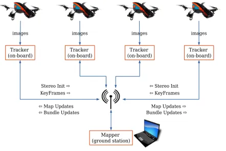
An overview of the system is shown in Figure 1. In our system the MAVs handle both image acquisition and frame-to-frame tracking; having tracking and image capture running on the same device is key to the performance of our system for full discussion see Section V. The MAVs are all connected to the ground-station computer via a wireless link. The ground-station computer runs the Mapper which handles map creation and optimization. Each component within the system is very modular and therefore is very flexible in terms of hardware and software. Additionally while our target platform is aerial vehicles the architecture will support ground-based robots or hand-held devices (e.g tablets or mobile phones).
Tracker
(on-board) (on-board)Tracker (on-board)Tracker (on-board)Tracker
Mapper (ground station)
images images images images
KeyFrames ⇨ ⇦ KeyFrames
⇦ Map Updates ⇦ Bundle Updates
[image:2.612.327.548.52.200.2]Map Updates ⇨ Bundle Updates ⇨ Stereo Init ⇨ ⇦ Stereo Init
Fig. 1. Basic system overview.
II. SYSTEM OVERVIEW
A. The Map
A mapMin our system is defined as:
M= (P,K)
whereP is a sparse set of point features located in a global coordinate frameW. Each point feature is represented by an
8×8pixel textured region in the world. Theith point in the map is stored as
Pi= (UiW, dPi)
whereUW= (xW, yW, zW)is the points’ 3D position. The map also contains a set of keyframesKcaptured during the mapping process. Thejth keyframe in the map is stored as
Kj = (TjW,Ij,Cj, dKj)
whereTW = (xW, yW, zW,ΦW,ΘW,ΨW)is the 3D cam-era pose of the captured frame,Iis a 4 level image pyramid. Cis a set of point measurements wherecij = (Pi,Kj, CMj)
is a measurement of point Pi in keyframe Kj and CMj is
the camera projection derivatives for keyframej.
A notable aspect of Klien and Murray’s approach is the fact that the pixels making up each pointPi are not stored.
Instead the point descriptor, defined as dP = (s, y, l), represents a pointer to the source keyframe s, the source pyramid levelyand pixel locationl. Therefore it is necessary to retain the original image pyramidI for all keyframes. The keyframe descriptor is defined as dK = SBI(Iks), where
SBI (Small Blurry Image) is a function which generates a sub-sampled40x30pixel image from the lowest level of the image pyramid, applies a Gaussian blur (σ= 2.5pixels) and finally subtracts the mean image intensity. This descriptor is used for tracking recovery (see Section II-D).
B. Tracking
corner features for each level as it is more robust to self-similar structures and has higher repeatability than the origi-nal FAST detector. The tracker uses its current estimated pose to extract a subset of the set map-pointsPto search for in the current image. The tracker uses a two-stage tracking process; it first searches for a small number of map-points (50) at the coarsest pyramid levels and updates the pose from the coarse matches. Then a fine grained search, which re-projects and searches for a larger (1000-5000) set of points, is executed and a final pose estimate is calculated from all the matches found. In the original library [12] a new keyframe is only passed on to the mapper if tracking quality is high (quality is based on the ratio of expected points to points actually found) and sufficient distance from any previous keyframes has been reached. In order to compensate for the potential latency between a new keyframe request and the response from the Mapper in DCTAM the tracker cannot request another new keyframe until a sufficient time tnewkf has elapsed.
The parameter tnewkf can be set manually or, in cases
where network performance fluctuates, dynamically using the actual round trip time recorded from periodic ping request to the ground-station. When a new keyframe is transmitted to the mapper we generate a new keyframe request: V = (I[0], TW,C). Where I[0]is the lowest level of the image pyramid (i.e the original image), TW is the current camera pose andCthe set of point measurements. To reduce the size of the message the image I[0]is compressed using lossless Portable Network Graphics (PNG) compression. This keeps the bandwidth requirements low while ensuring the mapper does not receive an image with compression artefacts. This is essential to ensure the mapper and tracker find the same features in the image.
C. Mapping
The Mapping process runs on the ground-station and is responsible for building the initial map using a stereo ini-tialization process and then further extending the map using the keyframes provided by the trackers. When the mapper receives a new keyframe requestV from a tracker it recon-structs the full keyframe structure Kj = (TjW,Ij,Cj, dKj)
from V. This is a repetition of some steps performed by the tracker but this is done to reduce the bandwidth require-ments. New map-points are added by triangulating points in neighbouring keyframes and the poses refined by local bundle adjustment as in the original library [12]. The bundle adjustment procedure aims to reduce the re-projection error i.e. expected position vs measured position for all map-points in keyframes using the set of measurementsC. It has the ef-fect of generating a new position for the afef-fected map-points which we define asUi0W for map-point Pi and a new pose
for each affected keyframe, defined as Ti0W for keyframe Ki. As in the original PTAM we use a local local bundle
adjustment procedure which operates on the new keyframe and it’s 4 closest (linear distance) neighbours. As this local bundle adjustment converges quickly we only generate a new map update once it has finished. A map update is defined as (P0,K0), where P0 is the set of newly generated
map-points andK0are the keyframes from which the points were generated. Note, it is only necessary to broadcast the source keyframe when multiple trackers are running as the tracker that sent the keyframe request already has this keyframe. In this case we again employ PNG compression to reduce the bandwidth requirements of the map update. The mapper augments each keyframe and map-point definition with the addition of a unique identifier idPi and idKj. This is a
globally unique identifier for each keyframe and map-point generated by the mapper. In addition to the local bundle adjustment, the mapper also runs a global bundle adjustment which refines the positions of all keyframes and map-points. Instead of generating a new map update, once the global bundle adjustment converges, we generate a bundle update defined as (BP0, . . . , BPn, BK0, . . . , BKm) where BPi =
(idPi, Ui0W)andBKj= (idKj, Ti0W). Again this is done to
further reduce the bandwidth requirements of our system.
D. Stereo Initialization and Tracking Failure Recovery
In the beginning there are no existing points from which to triangulate from, there the map initialization process requires a pair of keyframes with a sufficient baseline between them to triangulate the first set of map-points. The stereo initializa-tion request in our system is defined as(V0, V1, G)whereV0
andV1are the first two keyframes requests andGis the set of
2D point correspondences between the two keyframes (this is generated by the tracker during stereo initialization). The mapper uses the five-point stereo algorithm and RANSAC to compute the essential matrix and triangulate the first set of map-points. In the original PTAM library [12] this process was done manually using key presses making it difficult to replicate on a MAV. For our purposes we chose to automate the initialization process using our existing position controller and EKF framework (see Section III). There are many alternatives to generating the stereo pair required for map initialization such as using fiducial markers [4], multiple model filtering [10] or use of a stored map. We choose to make use of the additional sensors typical found on MAVs for our approach as it has additional benefits in terms of tracking performance and robustness.
The tracker can become lost due to lack of sufficient features in the environment or sufficiently rapid movements. The tracker uses the Small Blurry Image (SBI) re-localization method [14]. When tracking is lost the descriptordK from the current keyframe is compared to all keyframes using the sum-squared-difference. The keyframe with the lowest image difference is selected and the current position is set using the stored pose of the selected keyframe.
III. ADDITIONAL COMPONENTS
In conducting experiments to evaluate the proposed system we made use of some additional components previously presented in [11]. These are considered in this section.
A. Extended Kalman Filter (EKF)
Fig. 2. Results of the bandwidth experiment showing the bandwidth requirements for a single drone when operating alone (top) and as part of a team (bottom).
typical MAV sensors i.e. Inertial Measurement Units (which provide attitude and acceleration data), Sonar/Barometric Pressure (which provide altitude information) and Visual Odometry (for horizontal velocity estimates). This provides us with a complete (albeit noisy and prone to drift) local pose estimate for the MAV. This helps improve the performance of the system as, even when tracking fails, the MAV can continue using its own sensor data and may even be able to recover. Additionally, it allows us to automate the stereo initialization process. Using the state estimates from the EKF and the position controller (see next section) it is possible to capture the two keyframes required for the initialization with a reasonable certainty of the relative translation between the two frames. Unless otherwise stated all pose estimates in this paper come from the Tracker directly and not the EKF.
B. Optimal Reciprocal Collision Avoidance (ORCA) Position Controller
As our experiments involved several MAVs moving within the same area and we assume the MAVs are the only dynamic obstacle we needed a MAV-MAV collision avoidance solu-tion. We developed a position controller based around the work of Van den Berg et al. [15]. The ORCA approach uses an efficient linear program to calculate the nearest collision free velocity to the MAVs current goal. The system relies on knowing the current position and velocity of each MAV, which is broadcast by each Tracker. This allows us to move the MAVs around with a reasonable assurance they will not collide with each other.
IV. IMPLEMENTATION DETAILS
Our framework has been implemented in C++ and in-tegrated into the Robot Operating System (ROS) [16]. To further reduce bandwidth requirements we use the multi-master package multimulti-master fkie1to ensure only the DCTAM
1http://wiki.ros.org/multimaster_fkie
messages are transmitted over the wireless link between ground-station and MAVs.
V. RESULTS
We created a simulated environment of 20 metres by20
metres with sufficient texture on the floor to ensure there were always enough features for DCTAM to track. All simulated experiments were performed using a simple model of our quad-copter platform with a single downward-facing camera. We use the the 3D simulation environment Gazebo and the MAV plug-ins of Meyer et al. [17] to simulate the MAVs on-board sensors (IMU, Sonar, Barometric Pressure) and our own plug-in to simulate Visual Odometry, using typical values for sensor noise and drift. All simulated experiments were run on a desktop computer with a 3.4 Ghz Intel i7 processor and 16 GB of RAM (this also served as ground-station computer in the later hardware experiments). We show in Figure 2 the bandwidth requirements of a single MAV exploring our simulated area; the final map for this experiment was52keyframes and7240map-points. We show that even with a very large map the required bandwidth remains very low for our system. Significantly lower than streaming video directly (56 MB/s) to the ground-station as in [11] and even lower than the 1 MB/s required by [10] who use the same library as our system but who send the full colour image captured by the camera. We instead send only a compressed grey-scale image (we use lossless PNG compression with a very low compression rate to limit computation time) and are able to achieve a requirement of only 9 Kb/s for a single MAV and 42 Kb/s for a single MAV operating as part of a team. As stated previously, the additional bandwidth is required when sending keyframes to the other trackers in the team. A common artefact of wireless networks is high latency which can have a negative impact on a distributed system like ours. We conducted experiments where we introduced artificial random delays to determine its effect on our system.
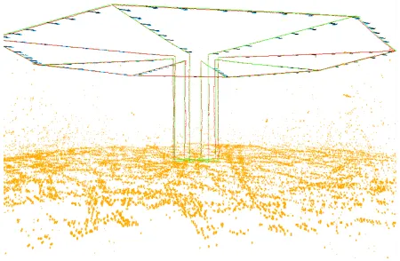
[image:4.612.332.535.530.708.2]Fig. 4. Experiment showing a team of 8 MAVs flying a predefined path mapping a flat area. The diagram shows the estimated path (red lines), ground truth path (green lines), map-points (orange points) and keyframe poses both estimated (blue arrows) and ground truth (black arrows).
[image:5.612.73.281.428.513.2]Fig. 5. 2D position plot of the results shown in Figure 4, ground truth paths are shown as dashed green lines.
Fig. 6. Evolution of RMS error for each MAV in Figure 4.
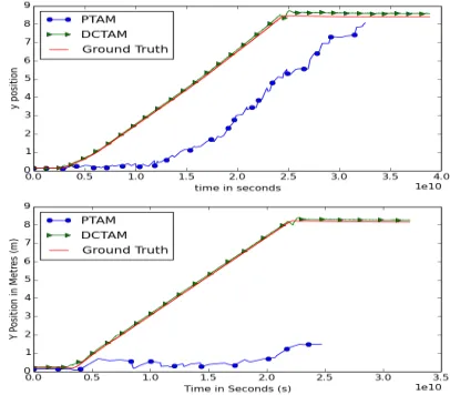
Figure 3 shows the results of two delay experiments we conducted, here a single MAV is flown at a constant speed in a single direction. We compare our system to our previous approach [11] where the video feed is streamed from the MAV to the ground-station. As the MAV is flying into a previously unmapped area both systems must capture new keyframes and add new points to the map. As the results show our system performs well even with a maximum delay of 1000 milliseconds. Delay of this kind can be compen-sated for using an EKF [2]; however, as the second delay experiment shows, tracking quickly fails with a large enough delay which cannot be compensated for. We extended the experiment to test the limits of our system and found that even with an extreme maximum delay of 30 seconds our
system continues to operate. This is only possible if the MAV is moving sufficiently slowly that newly added map-points reach the tracker before it needs them to maintain stable tracking. It is fairly trivial to keep track of updates from the map maker and adjust the behaviour of the MAV’s controller based on the current state of the system. If a tracker is waiting for new map-points from the mapmaker we can continuously reduce the MAVs speed in order to ensure it does not leave the mapped area before the new map-points arrive.
With the reductions in bandwidth and processing require-ments (from the distributed architecture) comes the ability to handle larger teams of MAVs. Figure 4 shows a screen shot of an experiment conducted with a team of 8 MAVs. We ran the system with maximum random delay of 1000 milliseconds to simulate a poor wireless network; typical values in our networks are from 250-500 milliseconds. Each MAV flies a pre-defined route mapping as they go; the total distance travelled was 139.4 metres with a final RMS error of 0.1 metres. Figure 6 shows the RMS error for each MAV plotted over time. The initial error is large as each MAV assumes its starting at 3D position (0,0,0). As each MAV localises itself within the map there is a significant jump as each MAV gets its first global pose estimate and then a steady convergence as more estimates are integrated into the EKF. Note that in the initial outward movement each MAV is tracking map-points generated from its own keyframes but as each MAV moves across to complete the octagon shape they move into areas already mapped by other MAVs. For this experiment the simulator was unable to generate camera images at the normal 30 FPS (Frames Per Second) instead only 5 FPS was obtainable, we were therefore forced to limit the speed of each MAV to 0.2 m/s (metres per second). For a camera with a standard 30 FPS update rate we are able to achieve speeds up to 7 m/s before tracking performance becomes unreliable. Of interest is the fact that past 7 m/s it is not the delay in processing introduced by the distributed architecture of DCTAM that impacts performance. Instead other factors such as the FPS of the camera or the rapid pitching of the MAV caused by the transition to forward flight have more impact. We intend to conduct a more in-depth study of capabilities of our framework eliminating these factors by using a higher FPS camera mounted on a stabilized gimbal.
A. Hardware Experiments
Fig. 7. Results showing tracking performance plotted against map size for both hardware platforms. The ATOM (top) and ODROID (bottom).
Fig. 8. Results of the repeated experiment on real hardware, the final RMS error was 0.06 metres.
Figure 7 shows the tracking times plotted against map size for both remote machines. The ODROID shows slightly better performance with an average tracking time of 0.01 milliseconds than the ATOM with an average of 0.06 mil-liseconds. Note the very short spikes in runtime coinciding with the arrival of a map update (resulting in an increase in map size). Both platforms show good performance and the trackers demonstrate constant-time performance regardless of map size. This is as a result of running the costly bundle adjustment procedure on the ground-station.
It may be argued that, in the experiment shown in Figure 4, artificial random delay does not approximate real world network conditions. In order to verify our approach under more realistic conditions we repeated the experiment on real hardware. A set of 8 netbook computers served as our proxy-MAVs, each playing back recorded images from the previous simulated experiment to on-board trackers. Each tracker was connected via our lab’s wireless network to the mapper running on the same ground-station computer. Figure 8 shows the results of the experiment, the final RMS error for the experiment improved to 0.06 metres, highlighting the benefit of the distributed processing approach of DCTAM.
VI. CONCLUSION
In this paper we have presented a distributed system for collaborative monocular SLAM with multiple MAVs. We successfully demonstrate the system’s robustness to the delay typically experienced with typical wireless networks. We also demonstrate the system is able to handle large teams of MAVs without degrading its performance. Future work will involve deploying the system with a team of physical MAVs based on the Pixhawk platform we are currently developing. Additional details including source code can be found at the following web-page: http://cgi.csc. liv.ac.uk/˜rmw/DCTAM.html
REFERENCES
[1] S. Weiss, D. Scaramuzza, and R. Siegwart, “Monocular-slam–based navigation for autonomous micro helicopters in gps-denied environ-ments,”Journal of Field Robotics, vol. 28, no. 6, pp. 854–874, 2011. [2] J. Engel, J. Sturm, and D. Cremers, “Camera-based navigation of a
low-cost quadrocopter,”IMU, vol. 320, p. 240, 2012.
[3] S. Ross, N. Melik-Barkhudarov, K. S. Shankar, A. Wendel, D. Dey, J. A. Bagnell, and M. Hebert, “Learning monocular reactive uav control in cluttered natural environments,” inInternational Conference on Robotics and Automation (ICRA). IEEE, 2013, pp. 1765–1772. [4] A. Wendel, M. Maurer, G. Graber, T. Pock, and H. Bischof, “Dense
reconstruction on-the-fly,” inComputer Vision and Pattern Recognition (CVPR), 2012 IEEE Conference on. IEEE, 2012, pp. 1450–1457. [5] D. Fox, W. Burgard, H. Kruppa, and S. Thrun, “A probabilistic
ap-proach to collaborative multi-robot localization,”Autonomous robots, vol. 8, no. 3, pp. 325–344, 2000.
[6] L. Carlone, M. K. Ng, J. Du, B. Bona, and M. Indri, “Rao-blackwellized particle filters multi robot slam with unknown initial correspondences and limited communication,” inInternational Con-ference on Robotics and Automation (ICRA). IEEE, 2010, pp. 243– 249.
[7] C. Forster, S. Lynen, L. Kneip, and D. Scaramuzza, “Collaborative monocular slam with multiple micro aerial vehicles,” inInternational Conference on Intelligent Robots and Systems (IROS), IEEE/RSJ. IEEE, 2013, pp. 3962–3970.
[8] A. Schmidt, “Multi-robot, ekf-based visual slam system,” inComputer Vision and Graphics. Springer, 2014, pp. 562–569.
[9] A. J. Davison, I. D. Reid, N. D. Molton, and O. Stasse, “Monoslam: Real-time single camera slam,”Pattern Analysis and Machine Intelli-gence, IEEE Transactions on, vol. 29, no. 6, pp. 1052–1067, 2007. [10] L. Riazuelo, J. Civera, and J. Montiel, “C 2 tam: A cloud framework
for cooperative tracking and mapping,” Robotics and Autonomous Systems, vol. 62, no. 4, pp. 401–413, 2014.
[11] R. Williams, B. Konev, and F. Coenen, “Multi-agent environment exploration with ar. drones,” in Advances in Autonomous Robotics Systems. Springer, 2014, pp. 60–71.
[12] G. Klein and D. Murray, “Parallel tracking and mapping for small ar workspaces,” inInternational Symposium on Mixed and Augmented Reality ISMAR 2007. IEEE, 2007, pp. 225–234.
[13] E. Mair, G. D. Hager, D. Burschka, M. Suppa, and G. Hirzinger, “Adaptive and generic corner detection based on the accelerated segment test,” inComputer Vision–ECCV. Springer, 2010, pp. 183– 196.
[14] G. Klein and D. Murray, “Improving the agility of keyframe-based slam,” in Computer Vision–ECCV 2008. Springer, 2008, pp. 802– 815.
[15] J. Van Den Berg, S. J. Guy, M. Lin, and D. Manocha, “Reciprocal n-body collision avoidance,” inRobotics research. Springer, 2011, pp. 3–19.
[16] M. Quigley, K. Conley, B. Gerkey, J. Faust, T. Foote, J. Leibs, R. Wheeler, and A. Y. Ng, “Ros: an open-source robot operating system,” inICRA workshop on open source software, vol. 3, 2009. [17] J. Meyer, A. Sendobry, S. Kohlbrecher, U. Klingauf, and O. von Stryk,
[image:6.612.76.282.267.414.2]