Article
Effect of Atomization Parameters on Size and
Morphology of Al-17Si Alloy Powder Produced by
Free Fall Atomizer
Dayanand M. Goudar
1,a,*
, V. C. Srivastava
2,b, and G. B. Rudrakshi
3,c1 Department of Mechanical Engineering, Tontadarya College of Engineering, Gadag 582 101, India 2 Metal Extraction and Forming Division, National Metallurgical Laboratory, Jamshedpur 831 007, India 3 Department of Mechanical Engineering, Basaveshwar Engineering College, Bagalkot 587 101, India
E-mail: a[email protected] (Corresponding author), b[email protected],
Abstract: The effect of process parameters on the characteristics of Al-17Si alloy powder produced by gas atomization using a free fall nozzle of different apex anglesof different apex angles was investigated. The axial gas velocity of gas jet away from the nozzle exit is measured for different operating pressures. The alloy was melted to a superheat temperature of 100,150 and 200°C and atomized by varying the gas flow rate and melt flow rate. The alloy powder size analysis were carried out by ASTM standard sieve with vibratory shaker and characterization of powder particles was accomplished by the parameters such as mass media, average size of powder particles; standard deviation and morphology of powder were studied by scanning electron microscopy. It is observed that decrease of apex angle results in axial velocity decreases in entire applied gas pressures range. Increase in apex angle results in decrease of gas jet length to metal stream collision, the median particle diameter of the powder increases resulting in decrease in particle irregularity. The median particle diameter of the powder has been shown to decrease almost linearly with increase in gas to melt flow (G/M) ratio. The sauter mean diameter variation, however, decreases slowly with increase in G/M ratio. Median particle diameter is significantly reduced with increase in the melt superheat.
Keywords:
Liquid metal atomization, powder processing, Al alloy, free fall gas atomizer.ENGINEERING JOURNAL Volume 21 Issue 1 Received 17 February 2016
1.
Introduction
Gas atomization process has been widely used in industry due to its advantages such as high capacity and high flexibility for the production of a wide range of ultrafine spherical metal powders. The rapidly solidified metal powder formed as a result of high cooling rate and deep under-cooling exhibits fine microstructure, chemical homogeneity, extended solid solution and metastable phase formation [1]. Atomization means disintegration of liquid metal into fine droplets by high velocity gas jets, which are simultaneously cooled down and solidified to form metal powders. The cooling of droplets takes place by the convective heat transfer in gas stream during their flight. The basic principle involved in atomization of liquids is to increase the surface area of the liquid stream until it becomes unstable and thus gets disintegrated [2]. Several investigators gave an overview on molten metal atomization techniques and devices [3-4]. The metal powder production by atomization of molten metal is done typically using twin-fluid atomization; in gas atomization the kinetic energy of an impinging high velocity gas jet disintegrates the continuous melt flow into droplets. The droplets in the spray are propelled away from the atomization zone under the effect of the high velocity gas jet. Larger amount of heat transfer between gas and droplets takes place for rapid partial cooling of the droplets [5]. The velocity difference between the melt stream and the impinging high speed gas jets attains an effective disintegration and leads to a wide size distribution of droplets (1 to 300 μm).
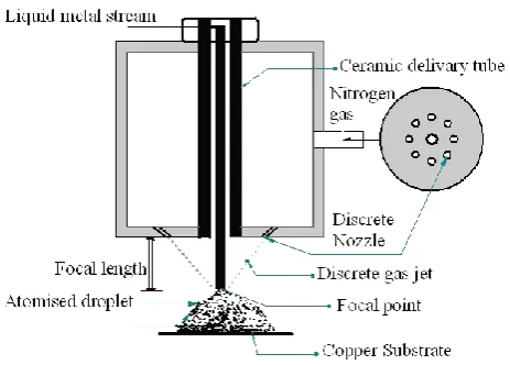
The atomization nozzle assemblies can be of two types, free-fall or close coupled, which are both external mixing atomizers. The design of close coupled nozzle as shown in Fig 1(a) is composed of an annular ring or concentric rings (around the central melt stream) containing a number of identical discrete gas nozzles which eject the gas jets for melt disintegration. The atomizing gas impinges on a melt stream at the end of the melt feed tube. Due to a short distance between the gas releasing point and the impingement point, less loss in kinetic energy of the atomizing gas. The close-coupled configuration generally tends to yield higher atomization efficiencies in terms of smaller particles at identical energy consumption. However, due to lower distance between the gas and melt exit, pre-films may generate at the delivery tube wall prior to interaction with the gas jet [6] and also more susceptible for freezing problem of the melt at the nozzle tip. These effects are due to the extensive cooling of the melt by the expanding gas flow. During isentropic gas expansion the gas temperature is lowered, also the close spatial coupling between gas and melt flow fields, a rapid cooling of the melt at the tip of the melt nozzle. There is also an interaction of gas stream with the tip of the delivery tube, which can form either positive pressure or negative pressure below the delivery tube. Under these varying pressure conditions an increase in melt flow rate or blowing back gas into the nozzle can occur. The free fall atomizer Fig. 1(b) mainly consists of discrete or annular gas jet which is directed at an angle α towards the melt stream. The gas jets in contact with the liquid stream in an atomization zone disintegrate the molten stream, which is located 20 to 50 mm away from the tip of the delivery tube [7]. Free-fall atomizer is less problematic than close-coupled atomizer in terms of thermal freezing since the melt stream and the gas jet are well separated at the exit of the melt from the delivery tube tip. The schematic sketch and details of free fall atomizer is shown in the Fig. 2
[image:2.595.167.434.565.702.2]Fig. 2. Schematic sketch and details of free fall atomizer.
Baolong zheng et al. [8] studied the effect of gas composition on cooling rate of liquid drople. The results showed that the cooling rate of droplets increases with decreasing powder size and can achieve in excess of 105K/s for powder <20 µm in diameter. Helium (He) is relatively low density, high thermal
conductivity and specific heat capacity which provides highest cooling rate than Argon (Ar) and Nitrogen (N2) gases. The high cooling capacity of He gas increases melt viscosity faster as compared with N2, Ar and
other gas mixtures. A rapid increase in viscosity has an adverse effect on the primary breakup of melt, as well as on the secondary breakup mechanisms. This leads to an increase in the average powder size. According to Lawely [9], He gas produces finer droplets compared to N2 and Ar. The recent experimental
work Unal et al. [10] showed that the powder produced by He, N2 and Ar, the median diameter obtained
are 13.5, 23.5 and 25µm respectively. Mathur et al [11] studied N2 and Ar as atomizing gas and reported
that the droplet size distribution does not change significantly but the amount of liquid in the droplet during deposition changes because the heat transfer coefficient of Ar is less compared to N2. Under similar
conditions the amount of liquid in the droplets is high for Ar gas as compared to N2 and Ar. The droplets
velocity is high during N2 gas atomization as compared to the Ar gas atomization [12]. The objective of
present study was to investigate the effects of process parameters and design of free fall atomizer on the powder morphology of Al-17Si alloy synthesized by N2 gas atomization. These observations have
potentially important implications for designing efficient liquid metal atomization processes for producing low-cost metal powders and spray formed materials.
2.
Experimental Procedures
2.1. Design of Free Fall Nozzle
[image:3.595.181.413.86.252.2]Fig. 3. Photograph of Free fall nozzle.
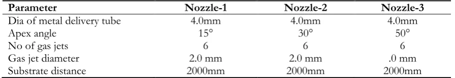
Table 1. Design parameters of free-fall nozzle used in the present study.
Parameter Nozzle-1 Nozzle-2 Nozzle-3
Dia of metal delivery tube 4.0mm 4.0mm 4.0mm
Apex angle 15° 30° 50°
No of gas jets 6 6 6
Gas jet diameter 2.0 mm 2.0 mm .0 mm
Substrate distance 2000mm 2000mm 2000mm
2.2. Gas Velocity, Gas Flow Rate and Gas Pressure Measurement
The axial gas velocity profile away from the nozzle exit is measured for different operating pressures. A schematic diagram of the arrangement used for the measurement of gas velocity is as shown in Fig. 4. The measurements were taken along the central axis of the gas jet formed below the convergence region. Pitot tube consists of 0.5 mm diameter tube such that its effect of flow field is negligible when placed in the flow field. The Pitot tube was placed in a brass jacket having diameter of 5 mm. However, jacket is tapered to 2.5 mm to generate a minimum resistance to the gas flow at the tube tip. The measurements are made for N2 gas injected by the atomizer at different pressures of 0.2, 0.35 and 0.45 MPa. Evaluation of gas velocities
[image:4.595.186.409.79.193.2]from the measured pressures takes into account compressibility of the gas phase. The gas passes through a rotometer which provides the fixed mass flow rate of the gas at different gas pressures. The pressure at the inlet of the rotometer is recorded by a pressure gauge.
Fig. 4. Schematic diagram of the experimental setup employed for the measurement of gas velocity and
gas pressure.
2.3. Gas to Melt Flow Rate (G/M) Ratio
[image:4.595.75.522.255.332.2] [image:4.595.185.415.521.651.2]2.4. Melt Atomization
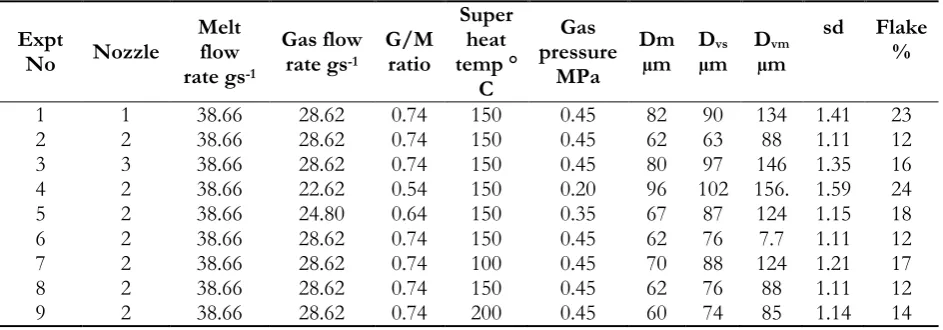
The Al-17Si alloy was melted in the crucible using a resistance heating furnace to a superheat temperature of 100, 150 and 200° C. The stopper rod is lifted to initiate the melt flow once the temperature is reached and homogenization time for 20 min. The process parameters used in the present investigation and the results obtained are shown in Table 2. At the end of each process run the powder was collected.
Table 2. Details of the atomization parameters and the results for different runs.
Expt
No Nozzle
Melt flow rate gs-1
Gas flow rate gs-1
G/M ratio Super heat temp ° C Gas pressure MPa Dm
µm Dµm vs Dµm vm
sd Flake %
1 1 38.66 28.62 0.74 150 0.45 82 90 134 1.41 23
2 2 38.66 28.62 0.74 150 0.45 62 63 88 1.11 12
3 3 38.66 28.62 0.74 150 0.45 80 97 146 1.35 16
4 2 38.66 22.62 0.54 150 0.20 96 102 156. 1.59 24
5 2 38.66 24.80 0.64 150 0.35 67 87 124 1.15 18
6 2 38.66 28.62 0.74 150 0.45 62 76 7.7 1.11 12
7 2 38.66 28.62 0.74 100 0.45 70 88 124 1.21 17
8 2 38.66 28.62 0.74 150 0.45 62 76 88 1.11 12
9 2 38.66 28.62 0.74 200 0.45 60 74 85 1.14 14
2.5. Characterization of Spray Powder
Gas atomized powder generally exhibits a wide size distribution. Over spray powder analysis. The ASTM standard sieve series standard for this work contains 25 µm, 37 µm, 44 µm, 53 µm, 64 µm, 76 µm, 89 µm, 106 µm, 150 µm, 212 µm, 300 µm, and 425 µm sizes. The sieved powders are subsequently weighed using an electronic balance with least count of 0.0001 gm. The characterization of powder particles was accomplished by the parameters such as the mass median diameter, average size of powder particles, standard deviation and morphology. The % mass fraction of different size range of particles is plotted against the particle size. The median particle size of a powder is obtained as the particle which corresponds to 50% of the cumulative mass frequency. In addition, the surface mean diameter (SMD) or sauter mean diameter (dvs) (Sauter Mean diameter defines the ratio of total spray volume to total surface area of all the
droplets) and volume mean diameter (dvm) (diameter for which half of the spray volume is made up of
smaller droplets) are determined. The sauter mean diameter of a sphere has same surface area per unit volume as the powder. Therefore, Dvs is a measure of the sphericity of the powder particles and is sensitive
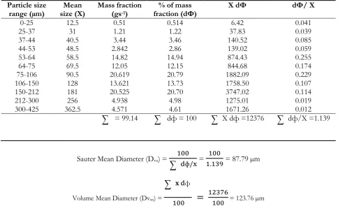
[image:5.595.63.535.203.368.2]Table 3. Atomization data of the powders produced in this investigation (Expt N0: 7).
Particle size
range (µm) size (Х) Mean Mass fraction (gs-1)
% of mass
fraction (dФ) Х dФ dФ/ Х
0-25 12.5 0.51 0.514 6.42 0.041
25-37 31 1.21 1.22 37.83 0.039
37-44 40.5 3.44 3.46 140.52 0.085
44-53 48.5 2.842 2.86 139.02 0.059
53-64 58.5 14.82 14.94 874.43 0.255
64-75 69.5 12.05 12.15 844.68 0.174
75-106 90.5 20.619 20.79 1882.09 0.229
106-150 128 13.621 13.73 1758.50 0.107
150-212 181 20.525 20.70 3747.02 0.114
212-300 256 4.938 4.98 1275.01 0.019
300-425 362.5 4.571 4.61 1671.26 0.012
= 99.14
dф = 100
X dф =12376
dф/X =1.139Sauter Mean Diameter (Dvs) =
== 87.79 µm
Volume Mean Diameter (Dvm) =
ф
= 123.76 µm
3.
Results and Discussion
3.1. Variation in Axial Velocity
The results of the axial gas velocity profile measurements are given in Fig. 5. The velocity profiles are obtained at the reservoir gas pressures of 0.20, 0.35 and 0.45 MPa. At geometric point, the velocities of gas measured for nozzle-1 show maximum values of 240, 256 and 260 ms-1. Further, the velocity decays
exponentially and reaches a value of 50 ms-1 at a distance of 390 mm away from the nozzle exit. The gas
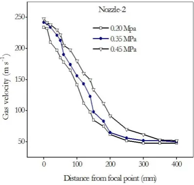
velocity measurement for nozzle-2 is shown in Fig. 6. It is observed from the figure that the maximum velocities are 234, 242 and 248 ms-1 at pressures of 0.2, 0.35 and 0.45 MPa respectively. Further, the rate of
velocity decay of nozzle-2 is faster as compared to nozzle-1. The measured central axis velocity components of N2 gas of nozzle-3 is shown in Fig. 7. The maximum gas velocity values of 215, 226 and
235 ms-1 at a gas pressure of 0.20, 0.35 and 0.45 MPa respectively are indicated at the focal point. The rate
[image:6.595.56.541.104.409.2]Fig. 5. Variation in axial gas velocity at different gas pressures in nozzle-1.
Fig. 6. Variation in axial gas velocity at different gas pressures of nozzle-2.
[image:7.595.182.381.292.482.2] [image:7.595.152.418.532.712.2]3.2. Size and Morphology of Powder
Figure 8 shows a typical variation of the mass fraction with particle size. The mass fraction depicts two peaks, one at around 25 µm and the other at 50 µm for the experiment No 7 as shown in Table 2. This indicates the prominence of these size ranges in the bulk of the powder samples. Very small size particles < 50 µm as well as large size particles >150 µm show low mass fraction compared to other size ranges of the powder particles. The influence of atomizing gas pressure on particle size distribution has been studied at three pressure levels (0.2, 0.35 and 0.45 MPa) at a constant gas flow rate of 30 lt. min-1. The median particle
diameter is determined from the cumulative mass fraction versus particle size. This is defined as the particle corresponding to 50% of cumulative mass fraction. With a high apex angle, splash back of atomizing liquid and/or freezing of molten metal at the exit of the nozzle is also expected. Increase in apex angle results in increase in gas jet length for fixed focal length. For smaller gas jet lengths, the median particle diameter of the powder decreases resulting in increase in particle irregularity. This is due to smaller divergence of gas stream causing effective transfer of energy from gas jet to the molten metal stream.
Fig. 8. Particle size distribution showing variation in mass fraction per µm.
[image:8.595.147.419.277.462.2]Fig. 9. Particle size distribution variation in cumulative mass fraction (Expt No-7).
Figure 10 shows the effect G/M ratio on the mean particle diameter. The median particle diameter of the powder has been shown to decrease almost linearly with increase in G/M ratio. The sauter mean diameter variation, however, decreases slowly with increase in G/M ratio. Overall observation of the effect of G/M ratio on mean size made in this investigation follows other reported trends [14]. The G/M ratio greater than some critical value, however, does not affect the mean particle size significantly. Consequently, further increase in the G/M ratio leads only to wastage of gas with marginal refinement in the size of the powder.
[image:9.595.152.414.87.274.2]The effect of reservoir gas pressure on the median particle size is presented in Fig. 11. The median particle diameter decreases with increase in gas pressure. Due to variation in gas pressure from 0.20 to 0.45 MPa the particle size decreases by 12.2%. With this variation in the median particle diameters, the geometric standard deviation varies from 1.11 to 1.71. It is observed from the results that the decrease in size is accompanied with decrease in standard deviation. The volume mean diameter decreases with increase in gas pressure. Whereas, sauter mean diameter shows a minimum and it decreases slowly with increase in gas pressure. This shows an increase in the sphericity of the powder with increase in gas pressure. Figure 12 shows the effect of melt superheat on the particle diameter. It has been depicted that the median particle diameter is significantly reduced from 70 to 62 µm (12.5% decrease in the median particle size) with increase in the melt superheat 100°C to 150°C. However, the effect of temperature does not result in significant reduction in mean size as the temperature is increased from 150°C to 200°C. This results in reduction of mean size from 62 to 60 µm.
[image:9.595.174.402.573.739.2]Fig. 11. Variation of mean powder particle size with gas pressure.
deposits are produced with the help of nozzle-2 after suitable choice of process variables within the experimental limitations. It is a general observation that the percentage flake decreases with increase in G/M ratio. There is no significant effect of melt superheat on percentage of flakes formed. The standard deviation seems to decrease with decrease in median particle diameter.
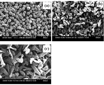
[image:11.595.70.492.323.667.2]The powder particle morphologies have been studied with scanning electron microscope (SEM) for different size range of particles produced at various processing conditions such as G/M ratio and melt superheat. Figure 12(a) shows the morphology of powders particles in the size range of < 25 µm produced at 0.45 MPa pressure and 150°C superheat using nozzle-2. It is depicted clearly in the micrograph that these ranges of powder particle have almost spherical morphology. Very few particles (< 15 µm size) seem to have perfectly spherical shape. Some of the relatively larger size particles show petal like shape. Intermediate size range powder particles, in the range 75-106 µm, exhibit coexisting spherical and elongated morphology as shown in Fig. 12(b). It is delineated clearly in the micrograph that larger particles have elongated and smaller ones have spherical morphology. The aspect ratio of elongated particles are as large as 3. A few particles exhibit dumbell shape morphology with a neck which appears to combine two spherical particles. Figure 12(c) shows the morphology of very large particles in the range of 300-425 µm. This invariably reveals large elongated particles with an aspect ratio ranging from 3 to 8. Only few of the powder particles can be seen to have near spherical morphology. Where-as, dumbell shape is very readily observed in this size range of powder particles.
Fig. 12. SEM morphology of powder particles generated at 0.45MPa, 0.74 G/M ratio and superheat temperature of 150°C using nozzle-2.(a) 0-25 µm (b) +75-106 µm (c) +300- 425 µm.
A comparison of the morphology of powder shown in Fig. 13 produced by nozzle-1, nozzle-2 and nozzle-3 at a gas pressure of 0.45 MPa, G/M ratio of 0.64 and super heat of 150○C. Figure 13(a) shows the
of overspray powder particles produced by nozzle-2 is shown in Fig. 13(b). It is depicted clearly in the micrograph that the powder particles have almost spherical morphology. Very small particles seem to have perfectly spherical shape and some of the relatively large size particles show dumbell like shape. Figure 13(c) shows the morphology of powder particles produced by nozzle-3. This shows that powders have relatively large size elongated particles. The size and morphology of powder particles have been found to have strong dependence on the G/M ratio and the melt temperature during atomization. A comparison of the over-spray powder particles shown in Fig 12(a) produced at G/M ratio of 0.74 with that of Fig. 13(b) produced at G/M ratio 0.64 shows that the powder particles generated at high G/M ratio have more sphericity.
[image:12.595.66.502.250.576.2]The effect of melt super heat on powder particle morphology can be seen from Fig. 14(a) show the morphology of powders (size range75-106 µm) produced at a superheat of 100°C. This shows that powders have relatively elongated morphology compared to powders (size range 75-106 µm) generated at 150°C of melt super-heat, as shown in Fig 14(b). The powders generated at 150°C display relatively large fraction of spherical particles compared to those produced at 100°C melt superheat.
Fig. 14. SEM micrographs showing the morphology of powder particles produced at different melt superheat temperature (a) 100°C and (b)150°C.
4.
Conclusions
The gas velocity profiles show an exponential decay with distance from the focal point. The increased apex angle, there is a decrease in the axial velocity due to increase in the normal component of gas jet velocity.
An increase in melt superheat from 100 to 200°C leads to decrease in the median particle size. This is mainly attributed to change in the viscosity of the liquid metal. ‘Sauter’ mean diameter decreases significantly at higher values of G/M ratio and melt superheat whereas, it shows strong dependence in the lower range of gas pressures.
The volume mean diameter decreases almost linearly with increase in G/M ratio, gas pressure and
melts temperature. The geometric standard deviation does not show specific trend.
SEM morphology of powder particles reveals that smaller particles posses spherical morphology,
whereas, large size particles have irregular and elongated morphology. Intermediate size range particles show co-existence of spherical and irregular morphology.
The sphericity of particles of the same range of powder particles increases with an increase in G/M ratio. An increase in melt superheat leads to an increase in sphericity of particles.
References
[1] J. T. Strauss and J. J. Dunkley, “An experimental and empirical study of close-coupled gas atomisation,” in Proceedings of Powder Metallurgy World Congress, Part 1, 2000, pp 347-350.
[2] G. G. Nasr, A. J. Yule, and L. Bendig, Industrial Sprays and Atomization: Design, Analysis and Applications. New York, 2002.
[3] E. J. Lavernia and Y. Wu, Spray Atomization and Deposition. Chicester, UK: John Wiley & Sons, 1996. [4] S. P.Mates and G. S. Settles, “A study of liquid metal atomization using close-coupled nozzles, Part 1:
Gas dynamic behavior,” Atomization and Spray, vol. 15, pp. 1-23, 2005.
[5] A. G.Leatham, A. J. W. Ogilvy, and P. F.Chesney, “Modern development in powder metallurgy,” vol.
19, no. 475-488, 1998.
[6] A. Lawley, “Atomization metal powder industries,” Federation,Princeton, NJ, 1992.
[7] J. T.Strauss and J. J. Dunkley, “An experimental and empirical study of close-coupled gas atomization,” in Proc World PM Congress, Kyoto, 2000.
[8] B. Zheng, Y. Lin, Y. Zhou, and E. J. Lavernia, “Gas atomization of amorphous aluminum powder:
Part II,” Metallurgical and Materials Transactions B., vol. 40, no. 6, pp. 995-1004, 2003.
[9] A. Lawely, “Atomization, the production of metal powders,” MPIF, Princeton, New Jersey, 1992. [10] P. Mathur, D. Apelian, and A. Lawley, “Analysis of the spray deposition process,” Acta Metall., vol. 37,
[11] A. Unal, “Production of rapidly solidified aluminium alloy powders by gas atomisation and their applications,” J. Powder metallurgy, vol. 33, no. 1, pp. 53-64, 1990.
[12] W. D. Cai and E. J. Lavernia, “Modeling of porosity during spray forming: Part I. Effects of processing parameters,” Metall. Mater. Trans B, vol. 29, no. 5, pp. 1085-1096, 1998.
[13] R. J. Grandzol and J. A. Tallmadge, “Effect of jet angle on water atomization,” Int. J. Powder Metall. PowderTechno, vol. 11, no. 2, pp. 103-116, 1975.
[14] J. J. Dunkley and J. D. Palmer, “Factors affecting particle size of atomized metal powders,” Powder Metall., vol. 29, no. 4, pp. 287-290,1986.
[15] S. A. Ozbilen, O. Unal, and T. Sheppard Ozbilen, “Influence of liquid metal properties on particle size of inert gas atomized powders,” Power Metallurgy, vol. 39, no. 1, pp. 44-52, 1996.
[16] V. C.Srivastava, S. N.Ojha, “Effect of process variables on powder characteristics during gas atomization of Pb-20Sn alloy,” Transactions of the Indian Institute of Metals, vol. 54, no. 5, pp. 85-192, 2001.
[17] B. N. Putimtsev “Effect of the thermo physical properties of gases and molten metal’s on the properties of atomized powders,” Soviet Powder Metallurgy and Metal Ceramics, vol. 11, no. 3, pp. 171-175, 1972.
[18] E. Klar and J. W. Fesko, “Gas and water atomization,” Journal of Powder Metallurgy, vol. 7, pp. 25-39, 1984.
[19] A. Unal, “Effect of processing variables on particle size in gas atomization of rapidly solidified aluminium powders,” Mater. Sci. Technol, vol. 3, no. 12, pp. 1029-1039, 1987.
[20] J. S. Thompson “A study of process variables in the production of aluminium powder by atomization,”
![Fig. 1. Design characteristics: α-angle formed by free-falling molten metal and atomizing medium jet; D- diameter of molten metal nozzle end; h- protrusion length of melt nozzle: Melt atomizer (a) Close-coupled nozzle; (b) Free fall [2]](https://thumb-us.123doks.com/thumbv2/123dok_us/8108601.235731/2.595.167.434.565.702/design-characteristics-falling-atomizing-diameter-protrusion-atomizer-coupled.webp)