Article
The Parametric Studied of High Pressure Gas Burner
Affect Thermal Efficiency
Panya Aroonjarattham
Department of Mechanical Engineering, Faculty of Engineering, Mahidol University, Nakornpathom, Thailand
E-mail: [email protected]
Abstract. The KB-5 high pressure gas burners were popularly and widely used in Thailand. This research was aimed to study the influence of four significant parameters, namely degrees of outer and inner ports and the number of outer and inner ports of high pressure gas burners, to the thermal efficiency by the experiments. The thermal efficiency was tested with reference to the standard industrial stoves in household with liquid petroleum gas (TIS 2312-2549). The results were shown the increasing angles of the outer port increased 13% thermal efficiency, the increasing numbers of outer port increased 5% thermal efficiency and increasing the numbers of inner port increased 7% thermal efficiency from the factory’s model. The increasing angles of inner port had less effect on thermal efficiency. The improving of high pressure gas burner will have modified by increased the numbers of outer and inner port and the angles of the outer port for the higher thermal efficiency than the factory’s design.
Keywords: High pressure burner, gas burner, thermal efficiency.
ENGINEERING JOURNAL Volume 20 Issue 3 Received 18 August 2015
1.
Introduction
The increasing of population growth in the world made the world’s energy crisis. Liquid petroleum gas (LPG) was the most commonly used for domestic application such as gas burners, which was widely used in food stand, restaurant and household in Thailand. The LPG consumption in Thailand was increasing every year as shown in Table 1.
Table 1. The LPG consumption in Thailand from year 2551 to 2555 B.E. [1].
Type Year (B.E.) 2551 2552 2553 2554 2555
Household 2,124 2,231 2,435 2,656 3,047
Industrial 658 586 769 718 614
Automotive 776 666 680 920 1,061
Petrochemical Industry 903 1,289 1,590 2,420 2,555
Electricity Production 328 435 466 131 110
Total 4,789 5,207 5,940 6,845 7,386
Unit: 1,000 Ton
The gas burner was simply to set up and use and had inexpensive price. The gas burner was classified by size of the burner head or port area which mixing LPG and air before burning in the combustion chamber. The main purpose of using LPG burners is to produce the maximum heat possible [2]. The domestic conventional burner has many types in the market but this research was focused to study the high pressure gas burner size KB-5, which had a highest market share of the high pressure gas burner from the market survey in Thailand.
The characteristic of burner head affect to the thermal efficiency and heating value of the burner. The research of low pressure gas burner had been a lot of studied on improvement and development of thermal efficiency such as Stubington et al., had studied the efficiency from the cooktop burner firing natural gas which found the thermal efficiency were affected by the thermal input and the load height to flame length ratio [3], Ashman et al., had used a cooktop burner to determine the loading height and thermal input and had found the decreasing thermal efficiency when increasing the loading high [4], but the research of high pressure gas burner has a few report on improvement and development. Srisathit and Aroonjarattham had studied the effect of high pressure gas burner parameters on thermal efficiency, which found the development of high pressure gas burners should focus on adjusting the degrees and number of inner and outer ports for the overall improvement of the thermal efficiency [5]. In addition, the Thai Industrial Standards Institute (TISI) had the standard of low pressure gas burner but did not set the standard for high pressure gas burner thus the standard that used in this work was based on the Standard Industrial Stoves in household with liquid petroleum gas (TIS 2312-2549) which consist of the characteristics of the high pressure gas burner for analyse the thermal efficiency.
The development of high pressure gas burner was focused to improve the structure of the burner head because the characteristic of the burner head be easily to modify. The port of the burner head was used to control the direction and the quantity of the flame to contact the object over the burner head, which more contact area between flame and the object increases the heat transfer from the burner head. This research aims to study the parameters of the burner head, which affect to the thermal efficiency of the domestic high pressure gas burner, and to improve the high pressure gas burner for increase the thermal efficiency.
2.
Materials and Methods
The high pressure gas burner was tested under the standard of industrial stove in household with liquid petroleum gas (TIS 2312-2549) the detail are as follow [6].
Testing room must be airy and no windy
LPG was used in this study with pure propane (C3H8)
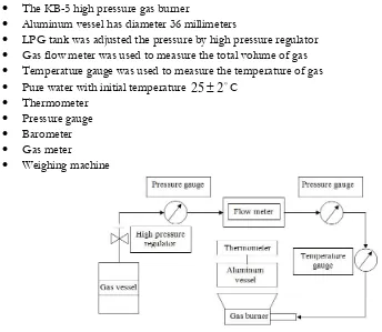
[image:2.595.63.534.191.295.2]The schematic diagram of the experimental apparatus system was shown in Fig. 1. The testing device consisted of
The KB-5 high pressure gas burner
Aluminum vessel has diameter 36 millimeters
LPG tank was adjusted the pressure by high pressure regulator
Gas flow meter was used to measure the total volume of gas
Temperature gauge was used to measure the temperature of gas
Pure water with initial temperature
2
25 C
Thermometer
Pressure gauge
Barometer
Gas meter
Weighing machine
Fig. 1. Schematic diagram of the experimental apparatus.
The experimental testing apparatus was shown in Fig. 2. The boundary condition of testing condition as follow
Testing pressure 40 kilopascals
Air inlet valve set for stoichiometric combustion
To clean the coating on gas stove by burn for 5 minutes
Testing begin by ignite the gas stove and record the initial temperature of gas and water
To record the final temperature of water and volume of gas consumption
Fig. 2. The experimental testing apparatus.
The thermal efficiency can be determined by measuring the elapsed time and gas consumption for heat the water from 25๐C to 90๐C. The thermal efficiency of the burner was defined by Eq. (1)
Thermal efficiency: (
th ) =
101
.
3
100
%
298
273
1 2
S
P
B
T
Q
V
T
T
c
m
m g p (1) [image:3.595.84.428.104.403.2] [image:3.595.218.377.525.661.2]p
c was the specific heat at constant pressure of water
K
kg
MJ
1T
andT
2 were the initial and final temperature of water respectively
C
V
was the volume of gas consumption
3m
Q
was the lower heating value of gas
3m
MJ
gT
was the gas temperature
C
B was the atmospheric pressure
kPa
m
P
was the pressure of the gas
kPa
S
was the saturated steam pressure at the gas temperatures
kPa
whose value can be found in Table 2.Table 2. The saturated steam pressure at the various gas temperatures[7].
C gT PsatkPa Tg
C PsatkPa0.15 0.661 52 13.51
2 0.679 57 17.19
7 0.990 62 21.67
12 1.387 67 27.13
17 1.917 72 33.72
22 2.617 77 41.63
27 3.531 82 51.00
32 4.712 87 62.09
37 6.221 92 75.14
42 8.132 97 90.40
47 10.530 100.15 101.33
The thirteen different models of domestic high pressure gas burners were selected to test and analyse. The selected burners must have similar characteristics, which include burner cover, burner head, mixing tube, injector, and air and gas control valve as shows in Fig. 3 for the purpose of comparing the four important parameters.
Fig. 3. The component of high pressure gas burner.
[image:4.595.63.534.308.470.2] [image:4.595.159.447.546.681.2]Fig. 4. The fourth parameters of burner head.
The development high pressure gas burner was selected only one from thirteen models, which pass the criteria for analyse and improved the number and the angle of the inner and outer port. The new burner head had drilled the holes to improve the thermal efficiency, which was compared with the factory model. The experiment of new burner head was divided to four cases and each case was fixed the other parameters as the factory design. The experiment testing conditions were shown in Table 3–6.
Table 3. The experiment testing condition improves the degrees of outer ports.
Burner
Head Angle of port Outer ports Inner ports
(degree) Number of port (port) Angle of port (degree) Number of port (port)
FM 50 36 50 12
A 55 36 50 12
B 60 36 50 12
C 65 36 50 12
D 70 36 50 12
E 75 36 50 12
F 80 36 50 12
G 85 36 50 12
H 90 36 50 12
*FM = Factory Model
Table 4. The experiment testing condition improves the numbers of outer ports.
Burner
Head Angle of port Outer ports Inner ports
(degree) Number of port (port) Angle of port (degree) Number of port (port)
FM 50 36 50 12
I 50 38 50 12
J 50 40 50 12
K 50 42 50 12
L 50 44 50 12
M 50 46 50 12
N 50 50 50 12
O 50 54 50 12
P 50 58 50 12
Q 50 62 50 12
[image:5.595.154.435.89.221.2] [image:5.595.63.534.361.516.2] [image:5.595.61.534.562.729.2]Table 5. The experiment testing condition improves the degrees of inner ports.
Burner
Head Angle of port Outer ports Inner ports
(degree) Number of port (port) Angle of port (degree) Number of port (port)
FM 50 36 50 12
R 50 36 55 12
S 50 36 60 12
T 50 36 65 12
U 50 36 70 12
V 50 36 75 12
W 50 36 80 12
X 50 36 85 12
Y 50 36 90 12
*FM = Factory Model
Table 6. The experiment testing condition improves the numbers of inner ports
Burner
Head Angle of port Outer ports Inner ports
(degree) Number of port (port) Angle of port (degree) Number of port (port)
FM 50 36 50 12
Z 50 36 50 14
AA 50 36 50 16
AB 50 36 50 18
AC 50 36 50 20
AD 50 36 50 22
AE 50 36 50 26
AF 50 36 50 30
AG 50 36 50 34
AH 50 36 50 38
AI 50 36 50 42
*FM = Factory Model
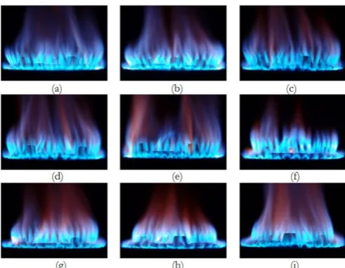
The new angles of outer port were varied from 50 to 90 degree and each case was increased for 5 degree. The flame direction of each improved degree was shown in Fig. 5.
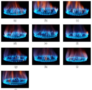
[image:6.595.64.535.103.256.2] [image:6.595.63.531.305.483.2] [image:6.595.174.420.543.734.2]The new numbers of outer port were increased from 36 to 62 ports and the first five cases was increased 2 ports for each case then the later four cases was increased 4 ports for each case. The increased ports affect to the flame direction as shown in Fig. 6.
Fig. 6. The flame direction of improved numbers of outer port under 40 kPa: (a) FM (b) I, (c) J, (d) K, (e) L, (f) M, (g) N, (h) O, (i) P and (j) Q.
The new angles of inner port were varied from 50 to 90 degree and each case was increased for 5 degree. The flame direction of each improved degree was shown in Fig. 7.
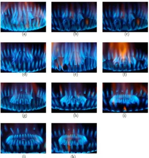
[image:7.595.150.445.141.430.2] [image:7.595.156.439.511.735.2]The new numbers of inner port were increased from 12 to 42 ports and the first five cases was increased 2 ports for each case then the later five cases was increased 4 ports for each case. The increased ports affect to the flame direction as shown in Fig. 8.
Fig. 8. The flame direction of improved numbers of outer port under 40 kPa: (a) FM, (b) Z, (c) AA, (d) AB, (e) AC, (f) AD, (g) AE, (h) AF, (i) AG, (j) AH and (k) AI.
3.
Result and Discussion
[image:8.595.147.449.141.461.2]Fig. 9. Thermal efficiency varied with testing pressure, which test with the factory model.
3.1. The Increasing Angles of Outer ports
The modified high pressure gas burner was developed by drilled the new hole of the burner. The varied angles of the new outer port were drilled with the jig from the factory to improve the degrees of the outer port. The new angle of outer port was increased every five degrees for each burner head as shown in Table 7.
Table 7. The percentage of thermal efficiency varied degrees of the outer port.
Burner Head Degrees of outer port (degree) Numbers of outer port (port) Thermal efficiency (%)
FM 50 36 48.48
A 55 36 49.39
B 60 36 50.45
C 65 36 50.85
D 70 36 50.88
E 75 36 54.80
F 80 36 53.83
G 85 36 53.27
H 90 36 51.04
[image:9.595.177.395.84.226.2] [image:9.595.70.527.367.505.2]The increased angle of the outer ports affected the higher thermal efficiency because the increased angle of the outer ports made more contact area between flames and the bottom of testing pot as shown in Fig. 10.
Fig. 10. The direction of flame from varied degrees of the outer port: (a) Ninety degrees and (b) Forty-five degrees.
The long contacting time between flame and bottom of testing pot get more heat conduction. The Newton law of cooling as shown in Eq. (2) was shown the heat transfer depending on the surface area of testing pot [22].
[image:9.595.156.435.558.681.2]
T
t
T
h
A
T
t
A
h
dt
dQ
env
(2)where
Q
was the thermal energy
J
h
was the heat transfer coefficient
K
m
W
2A was the heat transfer of surface area
2m
)
(
t
T
was the temperature of the object’s surface
K
env
T
was the temperature of the environment
K
t
T
was the time-dependent thermal gradient between environment and object
K
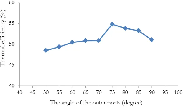
. [image:10.595.73.433.80.229.2]Thermal efficiency increased by increasing the angle of the outer port until the angle reach 75 degree that made the maximum thermal efficiency at 54.8% as show in Fig. 11.
Fig. 11. The increasing angles of the outer port affect thermal efficiency.
[image:10.595.122.435.274.458.2]The mixing tube was designed by reduce the cross sectional area for the fluid dynamic. The burner head suck the air from the surrounding by using the pressure from the injector to complete the combustion [23]. The air and gas mixed in the mixing tube before ignition as shown in Fig. 12. The seventy-five degree of outer port was shown the maximum thermal efficiency. The thermal efficiency had gradually decreased when the angle had increased more than seventy-five degree because the air-fuel ratio not suitable for combustion condition.
Fig. 12. The component of high pressure gas burner KB-5.
3.2. The Increasing Numbers of Outer Port
[image:10.595.170.429.584.680.2]of the burner head until the burner head had 46 outer ports. The varied numbers of the outer port was increased 4 ports for each case to find the maximum number of outer port for the burner head as shown in Fig. 13.
Fig. 13. The numbers of outer port compare to circumference: (a) 36 ports and (b) 62 ports.
The increasing numbers of outer port were drilled more ports to improve the thermal efficiency. The result from increased numbers of the outer port was shown in Table 8.
Table 8. The percentage of thermal efficiency varied numbers of the outer port.
Burner Head Degrees of outer port (degree) Numbers of outer port (port) Thermal efficiency (%)
FM 50 36 48.48
I 50 38 48.96
J 50 40 49.14
K 50 42 49.76
L 50 44 50.02
M 50 46 50.06
N 50 50 50.96
O 50 54 47.23
P 50 58 47.00
Q 50 62 47.49
[image:11.595.71.526.356.508.2]The increased numbers of outer port was increased more flame from the burner head that effect the higher thermal efficiency. The increased numbers of outer port from 36 to 50 ports made the increased thermal efficiency 4.8% after that increased numbers of outer ports made the thermal efficiency decreased as shown in Fig. 14 because the characteristic of the domestic high pressure gas burner has a limitation of air-fuel ratio mixture.
Fig. 14. The increasing numbers of the outer port affect thermal efficiency.
[image:11.595.165.436.587.733.2]3.3. The Increasing angles of Inner Port
The angle of the inner port was 50 degree from the factory model and the modified burner head was drilled the angles with 5 degree increasing as same as increased angle of the outer port. The result from increased angles of the inner port was shown in Table 9.
Table 9. The percentage of thermal efficiency varied degrees of the inner port.
Burner Head Degrees of inner port (degree) Numbers of inner port (port) Thermal efficiency (%)
FM 50 12 48.48
R 55 12 49.03
S 60 12 49.63
T 65 12 48.82
U 70 12 48.86
V 75 12 48.33
W 80 12 48.49
X 85 12 47.10
Y 90 12 47.71
[image:12.595.75.527.190.329.2]The improved burner head by increasing angles of inner ports had less effect to thermal efficiency. The thermal efficiency was decreased from increased angle of inner port more than 60 degree because the angle of inner port of factory model flow towards to the center of the testing pot as shown in Fig. 15(a) but the improved burner head was made the flame’s direction deviate from the center of the testing pot as shown in Fig. 15(b).
Fig. 15. The direction of flame from varied angles of the inner port: (a) Fifty degrees and (b) Ninety degrees.
The maximum thermal efficiency of the improved burner head occurred at 60 degrees. The higher angles than sixty degree decrease the thermal efficiency by reduced the contacting time between flame and bottom of the testing pot as shown in Fig. 16.
[image:12.595.138.461.418.547.2]Fig. 16. The increasing angles of the inner port affect thermal efficiency.
3.4. The Increasing Numbers of Inner Port
[image:13.595.68.527.390.553.2]The improved burner head for increased numbers of inner port was shown in Table 10 by first five cases was increased 2 ports for each case and after five cases, the burner head was increased 4 ports for each case.
Table 10. The percentage of thermal efficiency varied numbers of the inner port.
Burner Head Degrees of inner port (degree) Numbers of inner port (port) Thermal efficiency (%)
FM 50 12 48.48
Z 50 14 51.17
AA 50 16 51.23
AB 50 18 51.53
AC 50 20 51.76
AD 50 22 51.41
AE 50 26 50.39
AF 50 30 50.16
AG 50 34 50.28
AH 50 38 50.46
AI 50 42 50.09
The factory burner head has 12 inner ports, which is 18% of inner perimeter as shown in Fig. 17(a) and the maximum number of increased inner ports is 42 ports, which is 65% of inner perimeter as show in Fig. 17(b).
[image:13.595.159.434.607.740.2]The increasing numbers of inner port affect thermal efficiency as shown in Fig. 18. The increased numbers of inner ports make more contacting area between flame and bottom of testing pot than the factory model and the maximum thermal efficiency increase 7% from the factory burner head. The maximum thermal efficiency occur at 20 inner ports after that the value decrease by the limit of air-fuel ratio of characteristic of the high pressure gas burner.
Fig. 18. The increasing numbers of the inner port affect thermal efficiency.
4.
Conclusion
The development of high pressure gas burner, which increase the thermal efficiency was focused to modify the burner head of the factory model because the burner head was the mainly heat source. The modified burner head was improved 4 parameters that affect the thermal efficiency of high pressure gas burner including angle of outer and inner ports and number of outer and inner ports as shown in Fig. 19. The results of this research are as follow:
The increased angle of the outer port had increased the thermal efficiency approximately 13%.
The number of outer port has increased the thermal efficiency approximately 5%.
The increased angle of the inner port has increased the thermal efficiency approximately 2 %. The angle of inner port is rarely affected to thermal efficiency.
The number of inner port has increased the thermal efficiency approximately 7%.
Fig. 19. Thermal efficiency of high pressure gas burner improved four parameters.
The next step is to measure air-fuel ratio for analyze the relations of air and fuel, to modify the mixing tube for thoroughly mix air and fuel, and to construct the burner head consisting of 75 degree outer port, 60 degree inner port, 50 outer ports and 20 inner ports.
References
[1] The Energy Policy and Planning Office (EPPO), “Energy Statistics of Thailand,” 2013.
[2] S. S. Hou and C. H. Chou, “Parametric study of high-efficiency and low-emission gas burners,” Adv Mat Sci & Eng, vol. 2013, pp. 1–7, 2013.
[3] J. F. Stubington, G. Reashel, T. Murphy, R. Junus, P. J. Ashman, and G. D. Sergeamt, “Emissions and efficiency from production cooktopburners firing natural gas,” J Inst Energy, vol. 67, pp. 143–155, 1994.
[4] P. J. Ashman, R. Junus, J. F. Stubington, and G. D. Sergeamt, “The effects of load height on the emissions from a natural gas-fired domestic cooktop burner,” Combust Sci Technol, vol. 103, pp. 283– 298, 1994.
[5] S. Srisathit and P. Aroonjarattham, “The effects of high pressure gas burner parameters on thermal efficiency,” Key Engineering Materials, vol. 656–657, pp. 729–734, 2015.
[6] Department of Alternative Energy Development and Efficiency, “Energy efficiency, high-pressure gas,” Preparation of standards, the last edition, pp. 2–98, 2014.
[7] The Engineering Toolbox. (2014). Properties of Saturated Steam—SI Units [Online]. Available: http://www.engineeringtoolbox.com/saturated-steam-properties-d_101.html [Accessed: 19 January 2015].
[8] R. Junus, J. F. Stubington, and G. D. Sergeant, “The effects of design factors on emissions from natural gas cooktop burners,” Int J Environ Stud, vol. 45, no.2, pp. 101–121, 1994.
[9] Y. C. Ko, S. S. Hou, and T. H. Lin, “Laminar diffusion flames in a multi-port burner,” Combust Sci Technol, vol. 177, no. 8, pp. 1463–1484, 2005.
[10] Y. C. Ko and T. H. Lin, “Emissions and efficiency of a domestic gas stove burning natural gases with various compositions,” Energy convers Manage, vol. 44, no. 19, pp. 3001–3014, 2003.
[11] S. S. Hou and Y. C. Ko, “Effects of heating height on flame appearance, temperature field and efficiency of an impinging laminar jet flame used in domestic gas stoves,” Energy convers Manage, vol. 45, no. 9, pp. 1583–1595, 2004.
[13] A. Tamir, I. Elperin, and S. Yotzer, “Performance characteristics of a gas burner with a swirling central flame,” Energy, vol. 14, no. 7, pp. 373–382, 1989.
[14] S. Jugjai, S. Tia, and W. Trewetaskson, “Thermal efficiency improvement of an LPG gas cooker by a swirling central flame,” Int J Energy Res, vol. 25, no. 8, pp. 657–674, 2001.
[15] S. Jugjai and N. Rungsimuntuchart, “High efficiency heat-recirculating domestic gas burners,” Exp Therm Fluid Sci, vol. 26, no. 5, pp. 581–592, 2002.
[16] A. Tamir, “A swirling-flame combustor for lean mixture,” Combust Sci Technol, vol. 90, pp. 193–209, 1993.
[17] M. Y. Khan and A. Saxena, “Performance of LPG cooking stove using different design of burner heads,” International Journal of Engineering Research & Technology (IJERT), vol. 2, no. 7, pp. 656–659, 2013. [18] S. S. Hou, C. Y. Lee and T. H. Lin, “Efficiency and emissions of a new domestic gas burner with a
swirling flame,” Energy convers Manage, vol. 48, no. 5, pp. 1401–1410, 2007.
[19] P. Muthukumar, P. Anand, and P. Sachdeva, “Performance analysis of porous radiant burners used in LPG cooking stove,” Int J Energy & Environ, vol. 2, no. 2, pp. 367–374, 2011.
[20] S. S. Hou, “Improvement in thermal efficiency and reduction in CO emissions of domestic gas burners via various heat transfer mechanisms,” Final Report for ITRI (Industrial Technology Research Institute), Taiwan, ROC, 2005.
[21] I. C. Wang, S. S. Hou, and T. H. Lin, “Step effects on interacting jet flames,” in Proc. National Conference on Combustion Science and Technology, Kaohsiung, Taiwan, 2002, pp. 237–44.
[22] W. Trewetaskson, “Efficiency improvement of LPG domestics cooking stove,” Master of Engineering Thesis, Chemical Engineering, Faculty of Engineering, King Mongkut’s University of Technology Thonburi (KMUTT), Bangkok, Thailand, 1998.
![Table 1. The LPG consumption in Thailand from year 2551 to 2555 B.E. [1].](https://thumb-us.123doks.com/thumbv2/123dok_us/8109050.235848/2.595.63.534.191.295/table-lpg-consumption-thailand-year-b-e.webp)
![Table 2. The saturated steam pressure at the various gas temperatures [7].](https://thumb-us.123doks.com/thumbv2/123dok_us/8109050.235848/4.595.63.534.308.470/table-saturated-steam-pressure-various-gas-temperatures.webp)