Analysis of Human Faces
Using a
Measurement-Based Skin Reflectance Model
The Harvard community has made this
article openly available.
Please share
how
this access benefits you. Your story matters
Citation
Weyrich, Tim, Wojciech Matusik, Hanspeter Pfister, Bernd Bickel,
Craig Donner, Chien Tu, Janet McAndless, et al. 2006. Analysis of
human faces using a measurement-based skin reflectance model.
In Proceedings International Conference on Computer Graphics
and Interactive Techniques, ACM SIGGRAPH 2006 Papers: July 30
-August 03, 2006, Boston, Massachusetts, 1013-1024. New York, N.Y.:
ACM Press. Also published in ACM Transactions on Graphics 25(3):
1013-1024.
Published Version
doi:10.1145/1179352.1141987;doi:10.1145/1141911.1141987
Citable link
http://nrs.harvard.edu/urn-3:HUL.InstRepos:4101997
Terms of Use
This article was downloaded from Harvard University’s DASH
repository, and is made available under the terms and conditions
applicable to Other Posted Material, as set forth at
http://
Analysis of Human Faces using a Measurement-Based
Skin Reflectance Model
Tim Weyrich∗ Wojciech Matusik† Hanspeter Pfister† Bernd Bickel∗ Craig Donner‡ Chien Tu† Janet McAndless† Jinho Lee† Addy Ngan§ Henrik Wann Jensen‡ Markus Gross∗
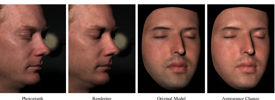
[image:2.612.70.545.142.316.2]Photograph Rendering Original Model Appearance Change
Figure 1: Photograph compared to a face rendered using our skin reflectance model. The rendered image was composited on top of the photograph. Right: Changing the albedo and BRDF using statistics of measured model parameters from a sample population.
Abstract
We have measured 3D face geometry, skin reflectance, and subsur-face scattering using custom-built devices for 149 subjects of vary-ing age, gender, and race. We developed a novel skin reflectance model whose parameters can be estimated from measurements. The model decomposes the large amount of measured skin data into a spatially-varying analytic BRDF, a diffuse albedo map, and diffuse subsurface scattering. Our model is intuitive, physically plausible, and – since we do not use the original measured data – easy to edit as well. High-quality renderings come close to reproducing real photographs. The analysis of the model parameters for our sam-ple population reveals variations according to subject age, gender, skin type, and external factors (e.g., sweat, cold, or makeup). Using our statistics, a user can edit the overall appearance of a face (e.g., changing skin type and age) or change small-scale features using texture synthesis (e.g., adding moles and freckles). We are making the collected statistics publicly available to the research community for applications in face synthesis and analysis.
Keywords: Face Modeling, Reflection Models, Data-Driven Mod-els
∗ETH Z¨urich, Email: [weyrich,bickel,grossm]@inf.ethz.ch
†MERL, Email: [matusik,pfister]@merl.com ‡UCSD, Email: [cdonner,henrik]@cs.ucsd.edu §MIT, Email: [email protected]
1
Introduction
One of the most difficult computer graphics challenges is creating digital faces that are indistinguishable from real ones. The process of capturing an actor’s performance and likeness has accurately been named “Digital Face Cloning.” Digital face cloning has many applications in movies, games, medicine, cosmetics, computer vi-sion, biometrics, and virtual reality. Despite recent progress, how-ever, it remains a challenging problem because humans are incred-ibly sensitive to the subtleties of real faces.
In this paper, we focus on modeling skin reflectance of human faces, an important aspect of face appearance. Our primary goal is to accurately capture and reproduce the face reflectance of a person. We use custom-built devices to measure 3D face geometry, light re-flection, and subsurface scattering. Our reflectance model consists of a spatially-varying analytic reflectance model (Torrance-Sparrow or Blinn-Phong), a diffuse albedo map, and diffuse scattering coef-ficients. We concisely describe the mathematics of the model and show how its components can be robustly estimated from measured data. The model is compact, intuitive, and easy to use. Images gen-erated from it come very close to real photographs (see Figure 1).
A second goal is to capture and describe the variation of face reflectance for a sample population. We measured the parameters of our reflectance model for 149 people of different race, gender, and age. The result is a unique database of spatially-varying para-meters for the Torrance-Sparrow and Blinn-Phong reflectance mod-els, histograms of skin albedo, and diffuse scattering parameters for faces. From this data we computed the distributions of the parame-ters (most of them are Gaussian) and analyzed them using statis-tical methods. We publish the key findings of our analysis in this paper, and make the complete statistical data available to the re-search community. To our knowledge, this is the first study of face reflectance of this kind.
computer vision. We also demonstrate how an artist can edit faces using the parameter distributions. For example, we can change the skin type of a model by transferring statistics of albedo and reflectance parameters (see Figure 1). We can also use texture syn-thesis/analysis to transfer small-scale skin features, such as moles and freckles. The combination of these approaches allows an artist to convincingly transfer face appearance between individuals.
2
Previous Work
Properties of human skin have been measured and studied exten-sively in the computer graphics, biomedical, and computer vi-sion communities. An excellent survey on the physiological and anatomical properties of skin and the state of the art in skin appear-ance modeling has been published by Igarashi et al. [2005]. In this section we provide an overview of the relevant work in the area of face appearance modeling in computer graphics.
Analytic Face Appearance Models: The simplest reflectance model for skin is the Bidirectional Reflectance Distribution
Func-tion (BRDF) [Nicodemus et al. 1977]. Dana et al. [1999]
measured the BRDF of skin and made the data available in the Columbia-Utrecht Reflectance and Texture (CuReT) database (http://www.cs.columbia.edu/CAVE/curet/). Because the data was not collectedin vivo it does not accurately reflect the properties of living skin. Marschner et al. [1999; 2000b] measured spatially uniform BRDFs on the foreheads of four subjects of different gen-der, race, and age. They observed that the BRDF of skin exhibits strong forward scattering in off-specular direction at grazing an-gles. In later work they augmented the uniform specular BRDF with a spatially-varying albedo texture [Marschner et al. 2000a]. Their BRDF model was used in the human face project at Walt Disney Studios [Williams 2005]. That project, which had a key in-fluence in the historical development of human face models (e.g., it was influential on the process developed for theMatrixsequels), was completed in 2001. Other researchers have estimated para-meters of uniform analytic BRDF models from photographs with static [Blanz and Vetter 1999; Paris et al. 2003] or varying illumi-nation [Georghiades 2003; Fuchs et al. 2005b]. Fuchs et al.[2005b] cluster different parts of the face, such as cheek, forehead, and lips, into regions. They estimate a spatially-varying diffuse albedo but assume specularity to be constant within each region. The funda-mental limitation of all these models is that they ignore subsurface scattering of light that is largely responsible for the soft appearance of facial skin.
Hanrahan and Krueger [1993] were the first to model subsurface scattering in skin using a diffuse constant and a lighting-dependent single scattering term. They described scattering and absorption parameters of skin using the Henyey-Greenstein function and com-pute scattering with Monte Carlo simulations. A similar approach was used by Ng and Li [2001]. To avoid expensive Monte Carlo simulations, Stam [2001] developed an analytic approximation to multiple subsurface scattering for skin with a rough surface. All of these models describe skin reflectance using a BRDF and ignore light scattering between different incoming and outgoing locations on the surface.
To describe the full effect of light scattering between two points on the surface one can use the Bidirectional Surface-Scattering Dis-tribution Function (BSSRDF). Krishnaswamy et al. [Krishnaswamy and Baranoski 2004] introduced a BSSRDF model for skin with spectral and biophysically-based parameters. The BSSRDF is eight-dimensional, making it very difficult to measure and repre-sent. Jensen et al. [2001] were the first to propose a practical low-dimensional analytic approximation for the BSSRDF of homoge-neous materials using diffusion theory. To estimate the parameters
of their model, they measure scattering of light in skin on a forearm in vivousing a white focused beam of light and a camera. We use their approximation for subsurface scattering. To estimate the para-meters of their model we developed a measurement device that can safely be used in faces (see Section 5.4). Donner and Jensen [2005] have applied a multi-layer diffusion model to the problem of ren-dering skin. Unfortunately, measuring the parameters of each layer of multi-layered translucent materials is a difficult problem.
Image-Based Face Models: Image-based models have provided highly realistic representations for human faces because they im-plicitly capture effects such as self-shadowing, inter-reflections, and subsurface scattering. Pighin et al. [1998] use view-dependent texture mapping [Debevec et al. 1996] to reproduce faces under static illumination conditions. More recent efforts allow varia-tions in lighting for static faces [Georghiades et al. 1999; De-bevec et al. 2000], expressions [Hawkins et al. 2004], and real-time performances [Wenger et al. 2005]. Debevec et al. [2000] present a process for creating realistic, relightable 3D face mod-els by mapping image-based reflectance characteristics onto 3D-scanned geometry. In order to change the viewpoint, they use color-space analysis to separate the image data into specular and diffuse components that can be extrapolated to new viewpoints. While their method does consider the aggregate behavior of subsurface scatter-ing, they do not model a specific diffusion parameter. Thus, unlike our approach, their method cannot produce correct subsurface scat-tering effects for closeup light sources or high-frequency spatially-varying illumination. Borshukov and Lewis [2003] combine an image-based model, an analytic surface BRDF, and an image-space approximation for subsurface scattering to create highly realistic face models for the movie industry. Sander et al. [2004] developed a variant of this method for real-time face rendering on modern graphics hardware.
Image-based models come at the price of extensive data storage. They are difficult to edit, and the measurements are not related to any physical model of light-skin interaction. It is very difficult to simulate local light sources and to reproduce spatially-varying illu-mination [Jones et al. 2005], especially if shadows from a distant light disagree with shadows from a local light. An example of this would be a light source close to the nose – even though the skin is illuminated, an image-based method would predict zero reflec-tion since a distant light from that direcreflec-tion would be blocked by the nose. In contrast to image-based methods, we measure a full BRDF at each surface point using a face-scanning dome similar to the LightStage by Debevec et al. [2002], but with more cameras (16). The resulting parametric face reflectance model has lower storage requirements than a full surface reflectance field. In addi-tion it is physically plausible, easy to render, and intuitive to edit.
Skin Color and Texture Models: Biophysical studies show that skin appearance is largely dependent on wavelength [Igarashi et al. 2005]. Angelopoulou et al. [2001] measured skin BRDF as a func-tion of wavelength for a sample populafunc-tion of 22 people and noted that five Gaussian basis functions reproduce the data well. The study was limited to 0◦incident and 4◦reflection angle.
3
Skin Reflectance Model
The BSSRDF is a functionS(xi,ωi,xo,ωo), whereωiis the direc-tion of the incident illuminadirec-tion at pointxi, andωois the observa-tion direcobserva-tion of radiance emitted at pointxo. The outgoing radiance L(xo,ωo)at a surface pointxoin directionωocan be computed by integrating the contribution of incoming radianceL(xi,ωi)for all incident directionsΩover the surfaceA:
L(xo,ωo) =
Z
A
Z
Ω
S(xi,ωi,xo,ωo)L(xi,ωi)(N·ωi)dωidA(xi). (1) We will use the notationdxifor(N·ωi)dA(xi).
We separate this integral into a specular BRDF term and a diffuse subsurface scattering term:
L(xo,ωo) =Lspecular(xo,ωo) +Ldi f f use(xo,ωo), (2) with:
Lspecular(xo,ωo) =
Z
Ω
fs(xo,ωo,ωi)L(xo,ωo)(N·ωi)dωi, (3) Ldi f f use(xo,ωo) =
Z
A
Z
Ω
Sd(xi,ωi,xo,ωo)L(xi,ωi)dωidxi. (4) Sd(xi,ωi,xo,ωo)is called the diffuse BSSRDF and fs(xo,ωo,ωi)is a surface BRDF. As observed in [Jensen and Buhler 2002], multiple scattering dominates in the case of skin and can be modeled as a purely diffuse subsurface scattering term and a specular term that ignores single scattering (see Figure 2).
Specular Reflection (BRDF) fs
Modulation Texture M
xo
ωo ωi
xi
ωi
[image:4.612.62.287.355.444.2]Homogeneous Subsurface Scattering R
Figure 2:Spatially-varying skin reflectance can be explained by a specular BRDF fsat the air-oil interface, and a diffuse reflectance component due to subsurface scattering. We model the diffuse re-flectance with a spatially-varying modulation texture M and a ho-mogeneous subsurface scattering component Rd.
The diffuse BSSRDF Sd is very difficult to acquire directly. Consequently, it is often decomposed into a product of lower-dimensional functions. A commonly used decomposition forSd is:
Sd(xi,ωi,xo,ωo)≈ 1
π fi(xi,ωi)Rd(xi,xo)fo(xo,ωo). (5)
HereRd(xi,xo)describes the diffuse subsurface reflectance of light entering at pointxi and exiting at pointxo. The diffuse surface reflectance/transmittance functionsfi(xi,ωi)and fo(xo,ωo)further attenuate the light at the entrance and exit points based on the in-coming and outgoing light directions, respectively.
The complete formula for our skin model is:
L(xo,ωo) =
Z
Ω
fs(xo,ωo,ωi)L(xo,ωi)(N·ωi)dωi (6) +
Z
A
Z
Ω
FtiRd(kxo−xik)M(xo)FtoL(xi,ωi)dωidxi. Like Hanrahan and Krueger [1993] and Jensen et al. [2001], we assume that skin is mostly smooth and use transmissive Fresnel
functionsFti=Ft(η,ωi)andFto=Ft(η,ωo). We useηu1.38 as the relative index of refraction between skin and air for the Fresnel terms [Tuchin 2000].
We model the diffuse reflectance using a homogeneous subsur-face reflectance termRd(kxo−xik)and a spatially-varying modu-lation texture M(xo)[Fuchs et al. 2005a]. Intuitively, this modu-lation texture represents a spatially-varying absorptive film of zero thickness on top of homogeneously scattering material (see Fig-ure 2). To model homogeneous subsurface scattering we use the dipole diffusion approximation by Jensen et al. [2001]. It simpli-fiesRd(xi,xo)to a rotationally-symmetric functionRd(kxo−xik), orRd(r)with radiusr. Jensen and Buhler [Jensen and Buhler 2002] develop fast rendering methods for this approximation, and Donner and Jensen [2005] extend it to a multipole approximation for mul-tiple layers of translucent materials.
Our formulation in Equation (6) was motivated by the skin model shown in Figure 2. Goesele et al. [2004] assume fi(xi,ωi) and fo(xo,ωo)to be constant. To model inhomogeneous translucent materials, they exhaustively measureRd(xi,xo)and tabulate the re-sults. In follow-up work [Fuchs et al. 2005a] they fit a sum of Gaus-sians to the tabulated values ofRd(xi,xo)to model anisotropic scat-tering. However, acquiringRd(xi,xo)directly requires a substantial experimental setup (controlled laser illumination from different an-gles) that is not applicable for human faces.
Donner and Jensen [2005] use spatially-varying diffuse trans-mission functions ρdt(xi,ωi) =1−
R
Ωfs(xi,ωi,ωo)(ωo·n)dωo (similarly forρdt(xo,ωo)). They integrate a BRDF at the surface over the hemisphere of directions and tabulate the results to obtain the diffuse transmission functions. To capture materials with homo-geneous subsurface scattering and complex surface mesostructure (so-called quasi-homogeneous materials), Tong et al. [2005] mea-sure and tabulate a spatially-varying exit function fo(xo,ωo)and a uniform entrance functionfi(ωi). We now give an overview of how we measure and estimate the parameters of our model.
4
Parameter Estimation Overview
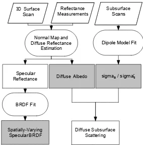
A block diagram of our processing pipeline is shown in Figure 3. We first capture the 3D geometry of the face using a commercial 3D
Normal Map and Diffuse Reflectance
Estimation
Specular
Reflectance Diffuse Albedo sigmaa / sigma's
Spatially-Varying Specular BRDF BRDF Fit
Diffuse Subsurface Scattering
Dipole Model Fit 3D Surface
Scan MeasurementsReflectance SubsurfaceScans
Figure 3:A block diagram of our data processing pipeline. Blocks in grey are the parameters of our skin reflectance model.
face scanner. Then we measure the total skin reflectanceL(xo,ωo)
[image:4.612.366.508.462.606.2]The reflectance measurements are registered to the 3D geometry and combined into lumitexels [Lensch et al. 2001]. Each lumitexel stores samples of the skin BRDF fr(xo,ωi,ωo). We estimate the diffuse reflectanceα(xo)offrusing a stable minimum of lumitexel samples. Note that this diffuse reflectance encompasses the effects of the diffuse subsurface scatteringRd(r)and the modulation tex-tureM(xo). We storeα(xo)in a diffuse albedo map and subtract
1
πFt(η,ωi)α(xo)Ft(η,ωo)from fr(xo,ωi,ωo). To the remaining
specular reflectance fs(xo,ωi,ωo)we fit the analytic BRDF func-tion.
The diffuse subsurface reflectanceRd(r)and the modulation tex-tureM(xo)cannot be measured directly on human subjects. Instead, we measure their combined effectR(r)at a few locations in the face using a special contact device. To our measurementsR(r)we fit the analytic dipole approximation of Jensen et al. [2001] and store the reduced scattering coefficientσs0and the absorption coefficientσa. Similar to Donner and Jensen [2005] we derive that:
Rd(r)M(xo) =R(r)
α(xo)
αavg
, (7)
whereαavgis the average albedo. We use the albedo mapα(xo), the average of all albedo map valuesαavg, and the dipole approxi-mation forR(r)to computeRd(r)M(xo)in Equation (6).
In summary, the parameters for each face are the spatially-varying coefficients of the specular BRDF fs, an albedo map with diffuse reflectance valuesα(xo), and the values forσs0andσa. Sec-tion 6 describes how this data is used for rendering. We now scribe each of these measurement and processing steps in more de-tail.
[image:5.612.322.555.52.123.2]5
Measurement System
Figure 4 shows a photograph of our face-scanning dome. The
sub-Figure 4:The face-scanning dome consists of 16 digital cameras, 150 LED light sources, and a commercial 3D face-scanning system.
ject sits in a chair with a headrest to keep the head still during the capture process. The chair is surrounded by 16 cameras and 150 LED light sources that are mounted on a geodesic dome. The sys-tem sequentially turns on each light while simultaneously capturing images with all 16 cameras. We capture high-dynamic range (HDR) images [Debevec and Malik 1997] by immediately repeating the capture sequence with two different exposure settings. The com-plete sequence takes about 25 seconds for the two passes through all 150 light sources (limited by the frame rate of the cameras). To minimize the risk of light-induced seizures we ask all subjects to
Figure 5:Facial detail shown in closeups. Left: Measured geom-etry before correction. Middle: Corrected high-quality geomgeom-etry. No normal map was used; the surface detail is due to the actual geometry of the model. Right: Comparison photo.
close their eyes. We report more details about the system and its calibration procedure in [Weyrich et al. 2005].
A commercial face-scanning system from 3QTech
(www.3dmd.com) is placed behind openings of the dome. Using two structured light projectors and four cameras, it captures the complete 3D face geometry in less than one second. The output mesh contains about 40,000 triangles and resolves features as small as 1 mm. We clean the output mesh by manually cropping non-facial areas and fixing non-manifold issues and degenerate tri-angles. The cleaned mesh is refined using Loop-subdivision [Loop 1987] to obtain a high-resolution mesh with about 700,000 to 900,000 vertices. The subdivision implicitly removes noise.
Next, we compute a lumitexel [Lensch et al. 2001] at each vertex from the image reflectance samples. The lumitexel radiance val-uesL(xo,ωo)are normalized by the irradianceE(xo,ωi)to obtain BRDF sample values:
fr(xo,ωi,ωo) =
L(xo,ωo) E(xo,ωi)=
L(xo,ωo)
R
ΩL(ωi)(ωi·n)dωi
. (8)
We calibrate the radianceL(ωi)of each light source using a white ideal diffuse reflector (Fluorilon) and explicitly model the beam spread by a bi-variate 2nddegree polynomial [Weyrich et al. 2005]. We use shadow mapping to determine the visibility of lumitexel samples for each light source and camera. On average, a lumitexel contains about 900 BRDF samples per color channel, with many lumitexels having up to 1,200 samples. The numbers vary depend-ing on the lumitexel visibility. All processdepend-ing is performed on RGB data except where noted otherwise.
5.1 Geometry Processing
We estimate normals at each lumitexel from the reflectance data using photometric stereo [Barsky and Petrou 2001]. We compute a normal map for each of the camera views. Using the method by Nehab et al. [2005] we correct low-frequency bias of the normals. For each camera, we also compute the cosine between it and each normal and store the result as a blending weight in a texture. To compute the finaldiffuse normal map, we average all normals at each vertex weighted by their blending weights. To avoid seams at visibility boundaries between cameras, we slightly smooth the blending texture and the diffuse normal map using a Gaussian filter. Finally, we compute the high-resolution geometry by applying the method of Nehab et al. Figure 5 compares the measured 3QTech geometry to the final high-resolution mesh.
[image:5.612.60.291.413.586.2]Figure 6:Torrance-Sparrow model and (from left to right) (a) only diffuse normal map; (b) one diffuse and one global micro-normal map for specular reflection; (c) one diffuse and per-view micro-normal maps; (d) input photograph. Method (c) most accurately reproduces the specular highlights of the input image.
To improve the result, we usemicro-normalsto render the spec-ular component. Debevec et al. [Debevec et al. 2000] used micro-normals for a Torrance-Sparrow model on their specular term. They estimated improved normals using a specular reflection image ob-tained using cross-polarized lighting. For each camera viewpoint, we choose the sample with maximum value in each lumitexel. The half-way vector between the view direction and the sample’s light source direction is the micro-normal for this view. We either store these normals in per-camera micro-normal maps, or generate a sin-gle micro-normal map using the blending weights from before. Fig-ures 6 (b) and (c) show renderings with single or per-view micro-normal maps, respectively. Figure 6 (b) is better than (a), but only Figure 6 (c) accurately reproduces the highlights of the input im-age. The results in this paper were computed using per-view micro-normals. For between-camera views and animations we interpolate the micro-normals with angular interpolation [Debevec et al. 1996].
5.2 Diffuse Albedo Estimation
We estimate the total diffuse reflectanceα at each surface point from the lumitexel data. We assume that surface reflectance van-ishes for at least some of the observation angles, revealing pure diffuse reflectance. Accordingly, the total diffuse reflectance is the maximum α that is compliant with the observations, i.e., (1/π)α does not exceed the Fresnel-normalized BRDF samples
fr/(Ft(η,ωi)Ft(η,ωo)). We computeα as the minimum ratio
be-tween this Fresnel-normalizedfrand the unit diffuse reflectance:
α(xo) =min i
πfr(xo,ωo,ωi)
Ft(η,ωi)Ft(η,ωo). (9) In order to reduce outliers and the influence of motion artifacts, we determine a stable minimum by penalizing grazing observations and discarding theksmallest values. Theαvalues for each surface point are re-parameterized, interpolated, and stored as the diffuse albedo map.
5.3 BRDF Fit
The specular reflection is computed at each lumitexel by subtracting the total diffuse reflectance:
fs(xo,ωo,ωi) =fr(xo,ωo,ωi)−α(xo)
π Ft(η,ωi)Ft(η,ωo). (10)
Highlights on dielectric materials like skin are of the same color as the light source (white, in our case). Consequently, we convert the specular reflectance to grey scale to increase the stability of the BRDF fit. Unlike previous work [Marschner et al. 1999; Lensch et al. 2001; Fuchs et al. 2005b] we do not need to cluster reflectance data because our acquisition system collects enough samples for a spatially-varying BRDF fit at each vertex. The data for lumitexels
with a badly conditioned fit is interpolated during creation of the BRDF coefficient texture.
We fit the Blinn-Phong [Blinn 1977] and Torrance-Sparrow [Tor-rance and Sparrow 1967] isotropic BRDF models to the data. The Blinn-Phong model is the most widely used analytic reflectance model due to its simplicity:
fsBP=ρs n+2
2π cos
n
δ. (11) Hereδis the vector between the normalNand the half-way vector H,ρsis the scaling coefficient, andnis the specular exponent. The factor(n+2)/2πis for energy normalization so that the cosine lobe always integrates to one. This assures that 100% of the incident energy is reflected forρs=1.
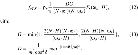
We also use the physically-based Torrance-Sparrow model:
fsT S=ρs 1
π
DG
(N·ωi)(N·ωo)Fr(ωo·H), (12)
with:
G=min{1,2(N·H)(N·ωo)
(ωo·H)
,2(N·H)(N·ωi)
(ωo·H)
}, (13)
D= 1 m2cos4δexp
−[(tanδ)/m]2
.
Gis the geometry term,Dis the Beckmann micro-facet distribution, and Fr is the reflective Fresnel term. The free variables are the scaling coefficientρsand the roughness parameterm.
For the fit we use the fitting procedure by Ngan et al. [2005]. The objective function of the optimization is the mean squared error between the measured BRDF fs and the target model fsM (either
fsBPor fsT S) with parameter vectorp:
E(p) = s
∑w[fs(ωi,ωo)cosθi−fsM(ωi,ωo;p)cosθi]2
∑w
. (14)
The sum is over the non-empty samples of the lumitexel, andθiis the elevation angle of incident direction. The weightwis a correc-tion term that allows us to ignore data withωiorωogreater than 80◦. Measurements close to extreme grazing angles are generally unreliable due to imprecisions in the registration between 3D geom-etry and camera images. We apply constrained nonlinear optimiza-tion based on sequential quadratic programming over the specular lobe parameters to minimize the error metric.
To assess the quality of our fit, we compare renderings from cam-era viewpoints to the actual photographs. The camcam-era and light source calibration data were used to produce identical conditions in the renderings. Figure 7 shows a comparison of the original and synthesized images with the same illumination and different BRDF models. The spatially-varying Blinn-Phong model (c) over-estimates the specular component and does not match the photo-graph as closely as the spatially-varying Torrance-Sparrow model (b). Nevertheless, it produces more accurate results compared to the spatially uniform Torrance-Sparrow BRDF (d).
[image:6.612.320.558.218.313.2](a) (b) (c) (d)
Figure 7:(a) Input photograph compared to our face model with (b) spatially-varying Torrance-Sparrow; (c) spatially-varying Blinn-Phong; and (d) uniform Torrance-Sparrow BRDF models.
intervention.” Given the high quality that we could achieve with the Torrance-Sparrow model, we decided not to further investigate the Lafortune model.
5.4 Measuring Translucency
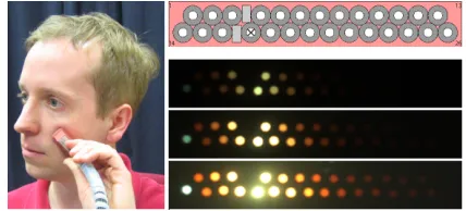
Our subsurface measurement device is an image-based version of a fiber optic spectrometer with a linear array of optical fiber de-tectors [Nickell et al. 2000] (see Figure 8). Similarly, more
so-Figure 8:Left: A picture of the sensor head with linear fiber array. The source fiber is lit. Right: The fiber array leads to a camera in a light-proof box. The box is cooled to minimize imaging sensor noise.
phisticated devices called Laser Doppler Flowmetry (LDF) probes are used to measure micro-circulatory blood flow and diffuse re-flectance in skin [Larsson et al. 2003]. The advantage of our device over LDF or the measurement procedure in [Jensen et al. 2001] is that it can be safely used in faces. Light from a white LED is coupled to a source fiber. The alignment of the fibers is linear to minimize sensor size. A sensor head holds the source fiber and 28 detection fibers. A digital camera records the light collected by the detector fibers. The camera and detector fibers are encased in a light-proof box with air cooling to minimize imager noise. We capture 23 images bracketed by 2/3 f-stops to compute an HDR im-age of the detector fibers. The total acquisition time is about 88 seconds.
[image:7.612.330.544.238.335.2]Figure 9 shows the sensor head placed on a face. We have chosen to measure three points where the sensor head can be placed reli-ably: forehead, cheek, and below the chin. For hygienic reasons we do not measure lips. We found that pressure variations on the skin caused by the mechanical movement of the sensor head influence the results. To maintain constant pressure between skin and sen-sor head we attached a silicone membrane connected to a suction pump. This greatly improves the repeatability of the measurements.
Figure 9:Left: The sensor head placed on a face. Top: Sensor fiber layout. The source fiber is denoted by a cross. Bottom: An HDR image of the detector fibers displayed with three different exposure values.
For more details on the subsurface device and calibration procedure see [Weyrich et al. 2005].
Previous work in diffuse reflectometry [Nickell et al. 2000] sug-gests that some areas of the human body exhibit anisotropic subsur-face scattering (e.g., the abdomen). We measured two-dimensional subsurface scattering on the abdomen, cheek, and forehead for a few subjects. We verified the presence of significant anisotropy in the abdominal region (see Figure 10). However, the plots show
Figure 10:Subsurface scattering curves for abdomen, cheek, and forehead measured along 16 1D profiles.
that the diffuse subsurface scattering of facial skin can be well ap-proximated with an isotropic scattering model. Consequently, we measure only a one-dimensional profile and assume rotational sym-metry.
We fit the analytic BSSRDF model of Jensen et al. [2001] to the data points of each subsurface measurement, providing us with the reduced scattering coefficientσs0and absorption coefficientσa. From the measuredσaandσs0data we can derive the effective trans-port coefficient:
σtr= p
3σa(σa+σs0)≈1/`d. (15)
[image:7.612.75.280.346.455.2] [image:7.612.324.551.480.553.2]Table 1 shows the mean and variance ofσtrfor a sample popula-tion of various people (see Secpopula-tion 7). The measurement points on
σtr Cheek Forehead Neck
(mm−1) Mean Var. Mean Var. Mean Var.
red 0.5572 0.1727 0.5443 0.0756 0.6911 0.2351
green 0.9751 0.2089 0.9831 0.1696 1.2488 0.3686
[image:8.612.54.300.92.145.2]blue 1.5494 0.1881 1.5499 0.2607 1.9159 0.4230
[image:8.612.57.291.259.374.2]Table 1:Mean and variance ofσtrin our dataset. cheek and forehead are quite similar in translucency. The measure-ment point on the neck underneath the chin shows a rather different mean, but also higher variance. This is probably due to measure-ment noise, as the sensor head is hard to place there.
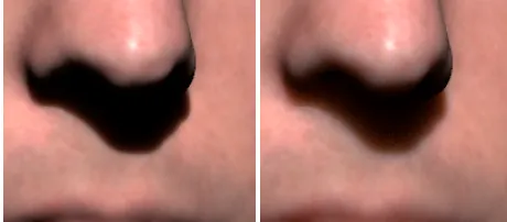
Figure 11 shows closeups of the subjects with minimum [1.0904,0.6376,0.6035] and maximum [2.8106,1.2607,0.6590] translucency values`d in our dataset. There are subtle differences
Figure 11:Photographs of subjects with minimum (left) and maxi-mum (right) translucency values in our dataset. The differences at shadow boundaries are subtle.
[image:8.612.57.287.468.569.2]visible at shadow boundaries. Figure 12 shows closeups computed with our model using the same minimum and maximum translu-cency values on one of our face models. Note that the model is
Figure 12: Synthetic images with minimum (left) and maximum (right) translucency values.
capable of reproducing the subtle differences of Figure 11. Translu-cency values`d do not vary much between measurement points and between individuals, which allows us to approximateσtrwith an average valueσtrAvg= [0.5508,0.9791,1.5497]for all subjects. This is the mean over all subjects of the measurements for the fore-head and cheek, ignoring the neck.
As observed by [Larsson et al. 2003], it is difficult to reliably measure the spatially-varying absorption coefficientσawith a con-tact device. However, usingσtrAvgwe can estimate spatially uni-form scattering parametersσaandσs0from skin albedowithoutany direct measurements of subsurface scattering. We use the diffuse
BRDF approximation by Jensen et al. [2001]:
SBRDF(xo,ωi,ωo) =
α0
2π(1+exp
−4 3
1+Fr
1−Fr √
3(1−α0)
)exp−
√
3(1−α0).
(16)
This approximation is valid for planar, homogeneously scattering materials under uniform directional illumination. It is quite accu-rate for the average total diffuse reflectanceαavg, which is the av-erage of all albedo map valuesα(xo). UsingSBRDF=αavg, we compute the apparent albedoα0 by inverting Equation (16) using a secant root finder. We derive the model parametersσs0 andσa fromα0andσtrAvgusing [Jensen and Buhler 2002]σs0=α0σt0and
σa=σt0−σs0, withσt0=σtrAvg/ p
3(1−α0). These diffuse scat-tering parameters are not spatially varying because we useαavgto compute them. Instead, we capture the spatial variation of diffuse reflectance using the modulation textureM(xo).
6
Rendering
We implemented our reflectance model using a high-quality Monte Carlo offline ray tracer. The direct surface reflectance was eval-uated using the Torrance-Sparrow BRDF model. The subsurface reflectance was computed using the diffusion dipole method as de-scribed in [Jensen et al. 2001] and modulated by the modulation tex-tureM(xo).M(xo)can be derived from Equation (7) as described in Section 4. Each image took approximately five minutes to render on a single Intel Xeon 3.06GHz workstation. Figure 13 shows compar-isons between real and synthetic images for different faces and dif-ferent viewpoints. The synthetic and real images look very similar, but not absolutely identical. The main limitation is a lack of sharp-ness, both in the texture and in geometry, mainly because accuracy in geometric calibration and alignment remain issues. The inten-sity and shape of the specular highlights in the synthetic images is sometimes underestimated. The shape of the specular highlights – especially on the forehead – is greatly affected by fine wrinkles and small pores. Several sources of error (measured 3D geometry, motion artifacts, calibration errors, camera noise, Bayer interpola-tion, errors in the photometric stereo estimations, etc.) prevent us from capturing the micro-normal geometry with 100% accuracy. Much higher-resolution and higher-quality face scans can be ob-tained by creating a plaster mold of the face and scanning it with a high-precision laser system. For example, the XYZRGB 3D scan-ning process originally developed by the Canadian National Re-search Center contributed significantly to the realism of the Disney project [Williams 2005] and theMatrixsequels. However, it would be prohibitive to scan more than one hundred subjects this way. It would also be difficult to correspond the 3D geometry with the im-age data from the face scanning dome due to registration errors, subtle changes in expressions, or motion artifacts. In addition, the molding compound may lead to sagging of facial features [Williams 2005]. We believe that our system strikes a good tradeoff between speed, convenience, and high image quality.
Facial hair is currently not explicitly represented in our model. Although the overall reflectance and geometry of the bearded per-son in Figure 13 has been captured, the beard is lacking some details that are visible in the photograph. We avoided scanning people with full beards or mustaches.
We model subsurface scattering using a single layer. However, skin consists of several layers that have different scattering and ab-sorption properties [Tuchin 2000]. The multi-layer dipole model of Donner et al. [2005] would provide a better approximation, but it is not clear how to measure its parametersin vivofor people of different skin types.
Skin Skin Color Sun Exposure Reaction Subjects
Type (M/F)
I Very white Always burn N/A
II White Usually burn 8 / 6
III White to olive Sometimes burn 49 / 18
IV Brown Rarely burn 40 / 8
V Dark brown Very rarely burn 13 / 2
[image:10.612.57.293.53.135.2]VI Black Never burn 4 / 1
Table 2: The Fitzpatrick skin type system and the number of sub-jects per skin type.
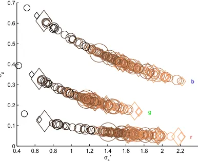
0.4 0.6 0.8 1 1.2 1.4 1.6 1.8 2 2.2
0 0.1 0.2 0.3 0.4 0.5 0.6 0.7
σs′ σa
r
g
[image:10.612.322.540.56.180.2]b
Figure 14: Plot ofσa[mm] andσs0[mm] for all subjects. Color encodes skin type (light = II, black = VI); shape encodes gender (= F,◦= M); marker size encodes age (larger = older). Skin absorption is highest for skin with low scattering and decreases for more highly scattering skin.
more opaque than actual skin [Igarashi et al. 2005]. In addition, our measurements are confined to RGB data. For example, the para-metersσaandσs0for skin are wavelength dependent [Igarashi et al. 2005]. Krishnaswamy and Baranoski [2004] developed a multi-spectral skin model and emphasize the importance of multi-spectral ren-dering in the context of skin.
7
Face Reflectance Analysis
We measured face reflectance for 149 subjects (114 male / 35 fe-male) of different age and race. The distribution by age is (M/F): 20s or younger (61/18), 30s (37/10), 40s (10/2), 50s or older (6/5). Because race is an ambiguous term (e.g., some Caucasians are darker than others), we classify the data by skin type according to the Fitzpatrick system [Fitzpatrick 1988]. Since we measured only two individuals of skin type I, we group types I and II together. Table 2 lists the number of subjects per skin type.
Analysis of Absorption and Scattering Parameters: We al-ready discussed the measured subsurface scattering data in Sec-tion 5.4. The absorpSec-tion coefficientσaand the reduced scattering coefficientσs0represent the amounts of light attenuation caused by absorption and multiple scattering, respectively. We estimate these parameters from the average albedoαavgand the average translu-cencyσtrAvg. Figure 14 shows the distribution of absorption and reduced scattering values for all subjects. Skin type is encoded by color (light = II, black = VI), gender by marker type (= F,◦= M), and age by marker size (larger = older). Subjects with skin type V and VI have higher absorption and lower scattering coefficients than subjects with skin type II or III. There seems to be no correla-tion with age. As expected, the absorpcorrela-tion coefficientσais highest
0.23 0.24 0.25 0.26 0.27 0.28 0.29 0.3 0.31 0.32 0.18
0.2 0.22 0.24 0.26 0.28 0.3 0.32 0.34
1
m ρs
2
3
4 6
7
8
9 10
Figure 15: Left: 10 face regions. Right: Variation of Torrance-Sparrow parameters per face region averaged over all subjects. The center of the ellipse indicates the mean. The axis of each ellipse shows the directions of most variation based on a PCA.
for the blue and green channels. In addition, the range ofσs0is much smaller for the green channel. These effects are due to the absorp-tion of blue and green light by blood in the deeper levels of the skin. The average absorptionσadecreases in people with higher scatter-ing coefficientσs0. The relationship is near-exponential since we are using the diffuse BRDF approximation by Jensen et al. (Equa-tion (16)).
Analysis of Torrance-Sparrow BRDF Parameters: To study the variations of the specular reflectance we analyzed the physically-based Torrance-Sparrow model parameters. Similar to the work by Fuchs et al. [Fuchs et al. 2005b], we distinguish the 10 different face regions shown in Figure 15 (left). For each re-gion, we randomly chose a few thousand vertices by marking them manually. We collected the BRDF parameters for the vertices and averaged them per region. Figure 15 (right) visualizes the resulting parameter distributions, averaged over all subjects. To create this visualization, we computed a 2×nmatrix for each region, wheren is the total number of samples in that region for all subjects. We then performed a Principal Component Analysis (PCA) on each matrix. The resulting eigenvectors and eigenvalues are the direc-tions and size of the ellipse axis, respectively. The centers of the ellipses have been translated to the mean values of the BRDF para-meters for that region.
As shown in Figure 15, the vermilion zone (or red zone) of the lips (8) exhibits a large parameter variation. Lips have smooth, glabrous skin, i.e., they have no follicles or small hairs. The epi-dermis is thin, almost transparent, and the blood vessels of the der-mis are close to the surface, giving raise to the red appearance of the lips. The reflectance variations are most likely due to circula-tion differences in these blood vessels and the highly folded der-mis, which results in the ridged appearance of the lips. Big pa-rameter variations can also be observed in regions 1 (mustache), 3 (eyebrows), 9 (chin), and 10 (beard). Male subjects contain fa-cial hair in these regions, which leads to noisy normal estimations and widely varying parameter distributions. Smoother facial areas, such as the forehead (2), eyelids (4), nose (6), and cheeks (7), show much smaller parameter variance. The highest specular scaling co-efficientsρsappear for nose (6), eyebrows (3), eyelids (4), lips (8), and forehead (2). The nose and forehead especially are areas of high sebum secretion, making them appear more specular. Not sur-prisingly, the nose (6) shows the smallest values for the roughness parametermbecause it lacks small facial wrinkles.
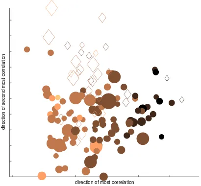
[image:10.612.73.266.169.326.2]direction of most correlation
[image:11.612.72.277.54.244.2]direction of second most correlation
Figure 16: Canonical correlation analysis of the Torrance-Sparrow BRDF parameters. Color encodes skin type (light = II, black = VI); shape encodes gender (= F,◦= M); marker size en-codes age (larger = older). Skin type is the only reliable predictor of BRDF parameters.
the age, and the skin type[II−V I]. The columns contain the data for each person. To visualize the matrixMwe tried linear (PCA) and non-linear dimensionality reduction techniques. However, the data is tightly clustered in a high-dimensional ball that cannot be reduced to fewer dimensions. Instead, we use Canonical Correla-tion Analysis (CCA) [Green et al. 1966]. CCA finds projecCorrela-tions of two multivariate datasets that are maximally correlated. Fig-ure 16 shows the output of CCA for the Torrance-Sparrow model. Here the data is projected (orthogonally) onto the two dimensions that are most strongly correlated with the experimental variables of skin type, gender, and age. The first dimension is best predicted by skin type (color), the second by gender (= F,◦= M). Age is encoded in marker size. The principal correlations are 0.768 and 0.585 (to mixtures of the experimental variables); the direct corre-lations are 0.766 for skin type, 0.573 for gender, and 0.537 for age. This indicates that CCA was not able to greatly improve the direct correlations. Maybe not surprisingly, skin type is the only reliable predictor for BRDF parameters.
To analyze variations of BRDF parameters due to external fac-tors, we also measured one male subject under several external conditions (normal, cold, hot, sweaty, with makeup, with lotion, and with powder). As expected, there are noticeable differences between these BRDFs, especially between lotion / hot and cold / powder.
Dissemination: The statistics of our face reflectance analysis of all subjects will be made public to the research community. We are releasing all reflectance data, such as BRDF coefficients, absorption and scattering coefficients, and albedo histograms, for each subject. In addition, we are providing an interactive applet that outputs av-erage parameter values and histograms based on user choice for gender, age, and skin type. This data will allow image synthesis, editing, and analysis of faces without having to acquire and process a large dataset of subjects.
8
Face Editing
Our face reflectance model has intuitive parameters for editing, such as BRDF parameters, average skin color, or detailed skin tex-ture. To change the surface reflectance of a model, we can either
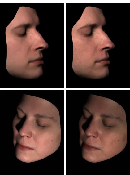
edit the parameters of the analytic BRDF model directly, or we can adjust them using the statistics from our database. For each face region, we can match the parameter histogram of the source face with another parameter histogram using the histogram interpola-tion technique presented in [Matusik et al. 2005]. This allows us to change a face BRDF based on, for example, different external con-ditions (e.g., from normal to lotion) (see Figure 17, bottom). We can also transfer skin color histograms from one subject to another. This allows us to change, for example, the skin type (e.g., from II to V) (see Figure 1, right).
To transfer skin texture, we use the texture analysis technique of Heeger and Bergen [1995]. We first transform the albedo map of each subject into a common and decorrelated color space using the method discussed in [Heeger and Bergen 1995][Section 3.5] and process each transformed color channel independently. We then compute statistics (histograms) of the original albedo map at full resolution, and of filter responses at different orientations and scales organized as a steerable pyramid. We use seven pyramid levels with four oriented filters, and down-sample the albedo map by a factor of two at each level. Each histogram has 256 bins. The first level of the pyramid is a low-pass and high-pass filter computed on the full-resolution albedo map. The output of the low-pass filter is a histogram of average skin color.
The histograms of all pyramid filter responses (30 total) and the histogram of the original albedo map are concatenated into a 256×31×3=23,808 element vectorH. To transfer skin tex-tures, we use the histogram vector H of a source and a target face and apply the histogram-matching technique of Heeger and Bergen [1995]. We can either use the histograms of the whole albedo map or restrict the analysis/synthesis to certain facial re-gions. Note that Heeger and Bergen start their texture synthesis with a noise image as the source. In our case it makes more sense to start from the source albedo map. To allow for sufficient variation during histogram matching, we add some noise to the source albedo map before we compute its histogram vectorH. A similar method was used by Tsumura et al. [2003] for synthesis of 2D skin textures, and by Cula and Dana [2002] to analyze bi-directional texture func-tions (BTFs) of skin patches. Figure 17 shows transfers of skin tex-ture, BRDF, and skin color for two face models. The translucency values of the source and result models remain the same. The exam-ple in Figure 1 (right) shows skin albedo and BRDF transfers. The resulting face appears lighter and shinier.
9
Conclusions and Future Work
In this paper we have proposed a simple and practical skin model. An important feature of our model is that all its parameters can be robustly estimated from measurements. This reduces the large amount of measured data to a manageable size, facilitates editing, and enables face appearance changes. Images from our model come close to reproducing photographs of real faces for arbitrary illumi-nation and pose. We fit our model to data of a large and diverse group of people. The analysis of this data provides insight into the variance of face reflectance parameters based on age, gender, or skin type. We are making the database with all statistics available to the research community for face synthesis and analysis.
Figure 17:Face appearance changes. Top: Transferring the freck-led skin texture of the subject in Figure 1 (left). Bottom: Changing the skin type (BRDF and albedo) from type III to type IV.
grazing angles [Koenderink and Pont 2003]. Our model does not take this into account.
We captured face reflectance on static, neutral faces. Equally important are expressions and face performances. For example, it is well known that the blood flow in skin changes based on fa-cial expressions. Our setup has the advantage that such reflectance changes could be captured in real-time.
10
Acknowledgments
We would like to thank Diego Nehab and Bruno L´evy for making their geometry processing software available to us, Agata Lukasin-ska and Natalie Charton for processing some of the face data, and Jennifer Roderick Pfister for proofreading the paper. John Barn-well, William “Crash” Yerazunis, and Freddy B¨urki helped with the construction of the measurement hardware, and Cliff Forlines produced the video. Many thanks also to Joe Marks for his contin-uing support of this project. Henrik Wann Jensen and Craig Don-ner were supported by a Sloan Fellowship and the National Science Foundation under Grant No. 0305399.
References
ANGELOPOULOU, E., MOLANA, R.,ANDDANIILIDIS, K. 2001. Multispectral skin color modeling. InIEEE Conf. on Comp. Vi-sion and Pattern Rec. (CVPR), 635–642.
BARSKY, S., AND PETROU, M. 2001. Colour photometric stereo: simultaneous reconstruction of local gradient and colour of rough textured surfaces. InEighth IEEE International Con-ference on Computer Vision, vol. 2, 600–605.
BLANZ, V.,ANDVETTER, T. 1999. A morphable model for the synthesis of 3D faces. Computer Graphics 33, Annual Confer-ence Series, 187–194.
BLINN, J. 1977. Models of light reflection for computer synthe-sized pictures. Computer Graphics 11, Annual Conference Se-ries, 192–198.
BORSHUKOV, G.,ANDLEWIS, J. 2003. Realistic human face ren-dering for the matix reloaded. InACM SIGGRAPH 2003 Con-ference Abstracts and Applications (Sketch).
CULA, O.,ANDDANA, K. 2002. Image-based skin analysis. In Texture 2002, The Second International Workshop on Texture Analysis and Synthesis, 35–42.
CULA, O., DANA, K., MURPHY, F.,ANDRAO, B. 2004. Bidirec-tional imaging and modeling of skin texture.IEEE Transactions on Biomedical Engineering 51, 12 (Dec.), 2148–2159.
CULA, O., DANA, K., MURPHY, F.,ANDRAO, B. 2005. Skin texture modeling.International Journal of Computer Vision 62, 1–2 (April–May), 97–119.
DANA, K. J.,VANGINNEKEN, B., NAYAR, S. K.,ANDKOEN
-DERINK, J. J. 1999. Reflectance and texture of real world sur-faces.ACM Transactions on Graphics 1, 18, 1–34.
DEBEVEC, P.,ANDMALIK, J. 1997. Recovering high dynamic range radiance maps from photographs. InComputer Graphics, SIGGRAPH 97 Proceedings, 369–378.
DEBEVEC, P., TAYLOR, C.,ANDMALIK, J. 1996. Modeling and rendering architecture from photographs: A hybrid geometry-and image-based approach. InComputer Graphics, SIGGRAPH 96 Proceedings, 11–20.
DEBEVEC, P., HAWKINS, T., TCHOU, C., DUIKER, H.-P., SAROKIN, W., AND SAGAR, M. 2000. Acquiring the re-flectance field of a human face. InComputer Graphics, SIG-GRAPH 2000 Proceedings, 145–156.
DEBEVEC, P., WENGER, A., TCHOU, C., GARDNER, A., WAESE, J., ANDHAWKINS, T. 2002. A lighting reproduc-tion approach to live-acreproduc-tion compositing.ACM Transactions on Graphics (SIGGRAPH 2002) 21, 3 (July), 547–556.
DONNER, C.,ANDJENSEN, H. W. 2005. Light diffusion in multi-layered translucent materials. ACM Transactions on Graphics 24, 3 (July), 1032–1039.
FITZPATRICK, T. 1988. The validity and practicality of sun-reactive skin types i through vi. Arch. Dermatology 124, 6 (June), 869–871.
FUCHS, C., GOESELE, M., CHEN, T.,ANDSEIDEL, H.-P. 2005. An empirical model for heterogeneous translucent objects. Tech. Rep. MPI-I-2005-4-006, Max-Planck Institute f¨ur Informatik, May.
FUCHS, M., , BLANZ, V., LENSCH, H.,ANDSEIDEL, H.-P. 2005. Reflectance from images: A model-based approach for human faces. Research Report MPI-I-2005-4-001, Max-Planck-Institut f¨ur Informatik, Stuhlsatzenhausweg 85, 66123 Saarbr¨ucken, Germany. Accepted for publication in IEEE TVCG.
GEORGHIADES, A., BELHUMEUR, P., AND KRIEGMAN, D. 1999. Illumination-based image synthesis: Creating novel im-ages of human faces under differing pose and lighting. In IEEE Workshop on Multi-View Modeling and Analysis of Visual Scenes, 47–54.
GEORGHIADES, A. 2003. Recovering 3-D shape and reflectance from a small number of photographs. InRendering Techniques, 230–240.
GOESELE, M., LENSCH, H., LANG, J., FUCHS, C., AND SEI
GREEN, P., HALBERT, M.,ANDROBINSON, P. 1966. Canonical analysis: An exposition and illustrative application. Marketing Research 3(Feb.), 32–39.
HANRAHAN, P.,ANDKRUEGER, W. 1993. Reflection from lay-ered surfaces due to subsurface scattering. InComputer Graph-ics, SIGGRAPH 93 Proceedings, 165–174.
HAWKINS, T., WENGER, A., TCHOU, C., GORANSSON, F.,AND
DEBEVEC, P. 2004. Animatable facial reflectance fields. In Ren-dering Techniques ’04 (Proceedings of the Second Eurographics Symposium on Rendering).
HEEGER, D., AND BERGEN, J. 1995. Pyramid-based texture analysis/synthesis. InProceedings of SIGGRAPH 95, Computer Graphics Proceedings, Annual Conference Series, 229–238. IGARASHI, T., NISHINO, K.,ANDNAYAR, S. 2005. The
appear-ance of human skin. Tech. Rep. CUCS-024-05, Department of Computer Science, Columbia University, June.
JENSEN, H. W.,ANDBUHLER, J. 2002. A rapid hierarchical ren-dering technique for translucent materials. InComputer Graph-ics, SIGGRAPH 2002 Proceedings, 576–581.
JENSEN, H. W., MARSCHNER, S. R., LEVOY, M., ANDHAN
-RAHAN, P. 2001. A practical model for subsurface light trans-port. InComputer Graphics, SIGGRAPH 2001 Proceedings, 511–518.
JONES, A., GARDNER, A., BOLAS, M., MCDOWALL, I.,AND
DEBEVEC, P. 2005. Performance geometry capture for spa-tially varying relighting. InACM SIGGRAPH 2005 Conference Abstracts and Applications (Sketch).
KOENDERINK, J.,ANDPONT, S. 2003. The secret of velvety skin. Machine Vision and Application, 14, 260–268. Special Issue on Human Modeling, Analysis, and Synthesis.
KRISHNASWAMY, A., AND BARANOSKI, G. 2004. A biophysically-based spectral model of light interaction with hu-man skin.Computer Graphics Forum 23, 3 (Sept.), 331–340. LAFORTUNE, E., FOO, S.-C., TORRANCE, K., AND GREEN
-BERG, D. 1997. Non-linear approximation of reflectance func-tions. Computer Graphics 31, Annual Conference Series, 117– 126.
LARSSON, M., NILSSON, H., ANDSTROMBERG¨ , T. 2003. In vivo determination of local skin optical properties and photon path length by use of spatially resolved diffuse reflectance with applications in laser doppler flowmetry. Applied Optics 42, 1 (Jan.), 124–134.
LAWRENCE, J., RUSINKIEWICZ, S., AND RAMAMOORTHI, R. 2004. Efficient brdf importance sampling using a factored rep-resentation.ACM Transactions on Graphics 23, 3, 496–505. LENSCH, H., KAUTZ, J., GOESELE, M., HEIDRICH, W., AND
SEIDEL, H.-P. 2001. Image-based reconstruction of spatially varying materials. In Proceedings of the 12th Eurographics Workshop on Rendering, 104–115.
LOOP, C. 1987. Smooth Subdivision Surfaces based on Triangles. Master’s thesis, Department of Mathematics, University of Utah. MARSCHNER, S., WESTIN, S., LAFORTUNE, E., TORRANCE, K., ANDGREENBERG, D. 1999. Image-based BRDF mea-surement including human skin. InProceedings of the 10th Eu-rographics Workshop on Rendering, 139–152.
MARSCHNER, S., GUNETER, B.,ANDRAGHUPATHY, S. 2000. Modeling and rendering for realistic facial animation. In11th Eurographics Workshop on Rendering, 231–242.
MARSCHNER, S., WESTIN, S., LAFORTUNE, E., AND TOR
-RANCE, K. 2000. Image-based measurement of the Bidirec-tional Reflectance Distribution Function. Applied Optics 39, 16 (June), 2592–2600.
MATUSIK, W., ZWICKER, M.,ANDDURAND, F. 2005. Texture design using a simplicial complex of morphable textures. ACM Transactions on Graphics 24, 3, 787–794.
NEHAB, D., RUSINKIEWICZ, S., DAVIS, J.,ANDRAMAMOOR
-THI, R. 2005. Efficiently combining positions and normals for precise 3d geometry.ACM Transactions on Graphics 24, 3, 536– 543.
NG, C.,ANDLI, L. 2001. A multi-layered reflection model of nat-ural human skin. InComputer Graphics International, 249256. NGAN, A., DURAND, F.,ANDMATUSIK, W. 2005. Experimental
analysis of brdf models. InEurographics Symposium on Render-ing, 117–126.
NICKELL, S., HERMANN, M., ESSENPREIS, M., FARRELL, T. J., KRAMER, U., ANDPATTERSON, M. S. 2000. Anisotropy of light propagation in human skin. Phys. Med. Biol. 45, 2873– 2886.
NICODEMUS, F., RICHMOND, J., HSIA, J., GINSBERG, I.,AND
LIMPERIS, T. 1977. Geometric considerations and nomencla-ture for reflectance. Monograph 160, National Bureau of Stan-dards (US), October.
PARIS, S., SILLION, F.,ANDQUAN, L. 2003. Lightweight face relighting. InProceedings of Pacific Graphics, 41–50.
PIGHIN, F., HECKER, J., LISCHINSKI, D., SZELISKI, R., AND
SALESIN, D. 1998. Synthesizing realistic facial expressions from photographs. In Computer Graphics, vol. 32 of SIG-GRAPH 98 Proceedings, 75–84.
SANDER, P., GOSSELIN, D.,ANDMITCHELL, J. 2004. Real-time skin rendering on graphics hardware. SIGGRAPH 2004 Sketch. SHEFFER, A., LEVY, B., MOGILNITSKY, M., AND BO
-GOMYAKOV, A. 2005. ABF++: Fast and robust angle based flattening.ACM Transactions on Graphics 24, 2, 311–330. STAM, J. 2001. An illumination model for a skin layer bounded by
rough surfaces. InProceedings of the 12th Eurographics Work-shop on Rendering Techniques, Springer, Wien, Vienna, Austria, 39–52.
TONG, X., WANG, J., LIN, S., GUO, B.,ANDSHUM, H.-Y. 2005. Modeling and rendering of quasi-homogeneous materials.ACM Transactions on Graphics 24, 3, 1054–1061.
TORRANCE, K. E., AND SPARROW, E. M. 1967. Theory for off-specular reflection from roughened surfaces. Journal of the Optical Society of America 57, 1104–1114.
TSUMURA, N., OJIMA, N., SATO, K., SHIRAISHI, M., SHIMIZU, H., NABESHIMA, H., AKAZAKI, S., HORI, K.,ANDMIYAKE, Y. 2003. Image-based skin color and texture analysis/synthesis by extracting hemoglobin and melanin information in the skin. ACM Transactions on Graphics (SIGGRAPH 2003) 22, 3, 770– 779.
TUCHIN, V. 2000. Tissue Optics: Light Scattering Methods and Instruments for Medical Diagnosis. SPIE Press.
WENGER, A., GARDNER, A., TCHOU, C., UNGER, J., HAWKINS, T.,ANDDEBEVEC, P. 2005. Performance relight-ing and reflectance transformation with time-multiplexed illumi-nation.ACM Transactios on Graphics 24, 3, 756–764.
WEYRICH, T., MATUSIK, W., PFISTER, H., NGAN, A., AND
GROSS, M. 2005. Measuring skin reflectance and subsurface scattering. Tech. Rep. TR2005-046, Mitsubishi Electric Re-search Laboratories (MERL).