This is a repository copy of
Effect of cyclic freezing and thawing on the microstructure of
composite cements
.
White Rose Research Online URL for this paper:
http://eprints.whiterose.ac.uk/120074/
Version: Publishers draft (with formatting)
Proceedings Paper:
Adu-Amankwah, S, Black, L orcid.org/0000-0001-8531-4989, Skocek, J et al. (1 more
author) (2016) Effect of cyclic freezing and thawing on the microstructure of composite
cements. In: 36th Cement and Concrete Science Conference. 36th Annual Cement and
Concrete Science Conference, 05-06 Sep 2016, Cardiff, UK. Institute of Materials,
Minerals and Mining .
[email protected] https://eprints.whiterose.ac.uk/
Reuse
Unless indicated otherwise, fulltext items are protected by copyright with all rights reserved. The copyright exception in section 29 of the Copyright, Designs and Patents Act 1988 allows the making of a single copy solely for the purpose of non-commercial research or private study within the limits of fair dealing. The publisher or other rights-holder may allow further reproduction and re-use of this version - refer to the White Rose Research Online record for this item. Where records identify the publisher as the copyright holder, users can verify any specific terms of use on the publisher’s website.
Takedown
If you consider content in White Rose Research Online to be in breach of UK law, please notify us by
36thCement and Concrete Science Conference
Cardiff, 5th& 6thSeptember 2016
Paper Number P003
Effect of cyclic freezing and thawing on the microstructure of
composite cements
S. Adu-Amankwaha, L. Blacka, , J. Skocekb, M. Zajacb
aInstitute for Resilient Infrastructure, School of Civil Engineering, University of Leeds, LS2 9JT, UK
bHeidelbergCement Technology Center GmbH, Rohrbacher Str. 95, 69181 Leimen, Germany
ABSTRACT
Mixed performance of composite cements exposed to freeze-thaw has been reported. A detailed understanding of the degradation mechanism is also lacking. This study investigates the microstructure of composite slag cements with and without limestone subjected to cyclic freezing and thawing. Freeze-thaw was assessed on concrete samples in accordance with CEN/TR 15177 but with a modified temperature profile. Microstructure was characterized by SEM and thermogravimetric analysis. The results indicate decalcification through carbonation and then leaching as dominant degradation mechanisms. This has implications on the pore structure and hence the water suction capacity and progression of the ice-front in concrete.
1. INTRODUCTION
Concrete is susceptible to degradation under cyclic freezing and thawing (FT) conditions. The deterioration is perceived to be associated with stresses induced by frozen water inside the pores (Fagerlund, 1997; Powers, 1945; Setzer et al., 2004). Consequently, lowering the available capillary pores which can be filled when exposed to moisture or internal desiccation (e.g. high strength, or low w/c ratio concretes) or providing pressure relieving centers through air entrainment have proven effective in combating frost susceptibility. However, it is often the case that concretes with equivalent strength but prepared with different binders tend to exhibit differences in freeze-thaw performance (Balters and Ludwig, 2004).
Several FT mechanisms have been suggested. The hydraulic pressure theory (Powers, 1945; Powers and Helmuth, 1953) which considers exertion of stresses on the pore wall due to the higher volume of ice than the unfrozen water has been questioned on the basis of pores rarely over 91% saturated (Scherer and Valenza, 2005). The mico-ice lens model (Setzer, 2001) is the reverse of the above such that, unfrozen water is drawn to the ice nucleus from adjacent capillary/gel pores. This induces gel shrinkage and water suction into the pores during thawing. The osmotic pressure mechanism is similar to the micro-ice lens but relates more to the ionic species in the pore solution rather causing the flow of water.
Understanding the relationship between the microstructure and concrete frost resistance as a function of the cement composition is important for designing more resistant concretes. The present study in line with this assesses the microstructural
changes accompanying frost attack in composite cements and briefly evaluates the changes against the above-mentioned mechanisms of degradation.
2. EXPERIMENTAL
Three cements: CEM I 42.5R, 50 % CEM I 52.5R+50 % slag and 50 % CEM I 52.5R+40 % slag +10 % limestone herein referred to as C, CS and CS-L respectively were studied. The water/cement ratio for concrete and pastes was maintained at 0.5. For concretes, the mix design was based on the following predefined ratios: 320.3 kg/m3 cement, 2.5 % total air and 0.54 fine to coarse aggregate ratio. 20 % of the coarse aggregates (quartzite) were 10 mm or smaller with the remainder being under 20 mm. No air entrainment admixtures were used.
The internal damage and scaling tests were performed on concrete samples prepared according to EN 12390:2. Specimens were kept in the mould for 24 hours and then stored in water for 7 days after de-moulding. From the 8th day,
specimens were stored at ≈ 65 % RH and 20 °C
phase assemblage variations. The samples were kept sealed for 7 days before being crushed to 1-2 mm thick sizes.
Figure 1 Freeze-thaw profile
They were then exposed to the laboratory
conditions of ≈ 65 % RH and 20 °C to mimic the
surface behaviour of the concrete test surface. These were saturated for 7 days and then freeze-thawed in deionized water at a constant water/solid ratio of 1:100. The deionized water was recycled weekly. At predefined intervals, some samples were taken and hydration stopped by the solvent exchange with isopropanol and ether.
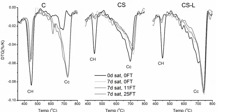
Simultaneous thermogravimetric analysis (STA) was carried out under nitrogen on 16-18 mg of additionally ground powder sample using a Stanton 780 Series Analyser. The heating range was 20-1000 C at a rate of 20 C/minute.
3. RESULTS AND DISCUSSION
Scaling and Internal damage
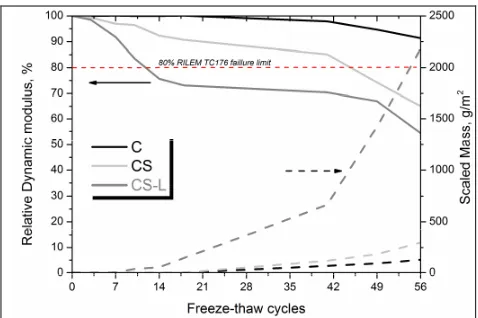
Scaling and Internal damage of the 3 mixes are shown in Figure 2. The internal damage and scaling in mix C were much lower compared to the composite cements and did not reach the 80 % failure limit even after 56 cycles. The mix CS-L was the worst performing such that the relative dynamic modulus was already lower than 80 % after 14 cycles. This is consistent with the scaling since significant loss of material commenced from this date. The limestone-free mix CS failed after about 42 cycles.
Considering that both mixes contained similar CEM I and sulphate contents, differences may be attributed to microstructure and its modifications during the exposure.
Microstructural changes - composite cements
SEM was used to follow the changes in the microstructure of concrete during freeze-thaw. The SEM images were collected with a JEOL 5900LV SEM at 15keV accelerating voltage. Figures 3(a-b) were acquired at locations away from the test surface. An intimate mix between aggregates, hydrates and non-hydrated slag particles was observed.
Figure 2 Effect of composition on internal damage and surface scaling (Note: RILEM TC 176 failure limit indicated with dashed horizontal line)
Significant changes in the microstructure were seen following the freeze-thaw exposure. Cracks were formed and propagated through the samples with time and in both composite cements (see Fig 3c-d), three regions (1-3) can be differentiated based on the grey scale. Region 1 is darker and visibly more porous. A closer look at this region (see Fig 3e-f) reveals pockets of hydrates particularly inner product C-S-H in mix CS. Around these were voids indicating eroded hydrates and outer product C-S-H. Mix CS-L also has voids but the remnant hydrates are not clearly identifiable and require further verification. However, projecting needle-like features can be seen but this clearly different from the C-S-H of the undamaged section (see Fig 3h). The intermediate regions (Fig 3g-h) show a mixture of the attributes of the degraded and non-degraded regions. These are more compact but the grey levels differed in the two composite cements and could be seen to be advancing over time. It is thus conceivable this progressing damage followed the advancing ice front. The changes in grey scale reflect changes in the portlandite and C-S-H potentially due to decalcification. In mix CS-L however, the grey scale was similar, but the micrographs revealed much coarser hydrates compared to the undamaged region 3.
[image:3.595.51.279.82.270.2]Figure 3.Microstructural changes associated with freeze-thaw of composite cements (Images obtained from 5mm concrete slices partially immersed in DIW for 25 freeze-thaw cycles)
Figure 4. Portlandite and calcium carbonate contents during cyclic freezing and thawing of the investigated cements
4. CONCLUSIONS
Concretes from neat and composite slag cements with and without limestone at 0.5 w/b ratio were tested for freeze-thaw resistance. The composite systems were less resistant and failed the 80% internal damage criteria before 56 cycles. The performance during freeze-thaw is a microstructural phenomenon which is related to the phase assemblages. The results above clearly show that differences between degraded and undamaged regions are in their porosities, calcium contents and hydrates assemblages. The outer product C-S-H degrades much quicker in the composite cements which reflects differences in the Ca/Si of the C-S-H. More CH in the neat cement buffers the C-S-H and thus curtails degradation. This has implications on how composite cements are assessed for frost durability.
References
Balters, U., Ludwig, U., 2004. Influence of cement type on resistance against freezing and thawing, with or without deicing chemicals, of cement mortar. Frost Resistance of Concrete, 34: 119.
Fagerlund, G., 1997. Internal frost attack - State of the art. In: Setzer, M.J., Auberg, R. (Eds.), Frost Resistance of Concrete. Proceedings of the International RILEM Workshop, Essen, pp. 321 - 338.
Fridh, K., 2005. Internal frost damage in concrete - experimental studies of destruction mechanisms, University of Lund. Pang, B., Zhou, Z., Cheng, X., Du, P., Xu, H., 2016. ITZ properties of
concrete with carbonated steel slag aggregate in salty freeze-thaw environment. Construction and Building Materials, 114: 162-171.
Powers, T.C., 1945. A Working Hypothesis for Further Studies of Frost Resistance of Concrete. ACI Journal Proceedings, 41(1): 245-272.
Powers, T.C., Helmuth, R.A., 1953. Theory of volume changes in hardened Portland cement paste during freezing. Highway Research Board, 32.
Scherer, G.W., Valenza, J., 2005. Mechanisms of frost damage. Materials science of concrete, 7(60): 209-246. Setzer, M.J., 2001. Micro-Ice-Lens Formation in Porous Solid.
Journal of Colloid and Interface Science, 243(1): 193-201. Setzer, M.J. et al., 2004. Test methods for frost resistance of concrete:
CIF Test: Capillary suction, Internal damage and freeze thaw test - Referennce method and alternative methods A and B. Materials and Structures, 37: 743 - 753. Sicat, E., Gong, F., Ueda, T., Zhang, D., 2014. Experimental
[image:5.595.57.446.259.451.2]