This is a repository copy of 2D Numerical ISPH Wave Tank for Complex Fluid-Structure
Coupling Problems.
White Rose Research Online URL for this paper:
http://eprints.whiterose.ac.uk/92991/
Version: Accepted Version
Article:
Liu, X., Shao, S., Lin, P. et al. (1 more author) (2016) 2D Numerical ISPH Wave Tank for
Complex Fluid-Structure Coupling Problems. International Journal of Offshore and Polar
Engineering (IJOPE), 26 (1). pp. 26-32. ISSN 1053-5381
10.17736/ijope.2016.ak09
[email protected]
https://eprints.whiterose.ac.uk/
Reuse
Unless indicated otherwise, fulltext items are protected by copyright with all rights reserved. The copyright
exception in section 29 of the Copyright, Designs and Patents Act 1988 allows the making of a single copy
solely for the purpose of non-commercial research or private study within the limits of fair dealing. The
publisher or other rights-holder may allow further reproduction and re-use of this version - refer to the White
Rose Research Online record for this item. Where records identify the publisher as the copyright holder,
users can verify any specific terms of use on the publisher’s website.
Takedown
If you consider content in White Rose Research Online to be in breach of UK law, please notify us by
*Author of correspondence, email: [email protected]
2D Numerical ISPH Wave Tank for Complex Fluid-Structure Coupling Problems
Xin Liu
College of Harbor, Coastal and Offshore Engineering, Hohai University Nanjing, China
Songdong Shao
Department of Civil and Structural Engineering, University of Sheffield Sheffield, UK
Sanjiangyuan Collaborative Innovation Center (SCIC), Qinghai University Xining, China
Pengzhi Lin*
State Key Laboratory of Hydraulics and Mountain River Engineering, Sichuan University Chengdu, China
Soon Keat Tan
NEWRI and Maritime Research Center, Nanyang Technological University Singapore
In this paper, we provide a hybrid incompressible Smoothed Particle Hydrodynamics (ISPH) model for fluid-structure interactions. The numerical algorithms include the mirroring treatment of solid boundary, free surface tracking, wave damping using sponge layer and fluid-solid coupling model. The proposed ISPH wave tank is applied to a series of wave-structure coupling problems including the sloshing in a baffled tank, solitary wave impact on an underwater obstacle, water entry of a cylinder and balance dynamics of a floating object. The simulation results demonstrate that the ISPH model provides an accurate simulation technique in various fluid-structure coupling studies.
KEYWORDS: ISPH, fluid-structure coupling, free surface, damping layer, force moment, structure rotation.
1. INTRODUCTION
The fluid-structure interaction is a common issue in the coastal and offshore hydrodynamics and according to the nature of interaction between the fluid and solid structure, it can be classified into two types, i.e. kinematic and dynamic couplings. The former assumes that the solid structure is either fixed or follows a prescribed motion, while the latter is much more complicated as the motion of the solid also depends on the instantaneous response of the fluid. The SPH modeling techniques have demonstrated great potentials in the dynamic coupling as there is no need to frequently generate or adjust the mesh system near the interface between the fluid and solid boundary, or treat the information exchanges between them,thus the solution algorithms can be simplified, which has considerable merits over many traditional Eulerian grid methods. A good understanding and efficient numerical simulation of the fluid-structure interactions is crucial to predict the fluid impact forces on the structure as well as the structural responses to the fluid in a wider engineering practice.
Since the pioneering work to introduce the concept of SPH to hydrodynamics (Monaghan, 1994), the method has been applied to a large number of fluid-structure interaction applications. Due to its mesh-free feature, the SPH method is well-suited to analyze many kinds of moving boundary and large surface deformation problems (Lind et al., 2012; Gotoh et al., 2014). By using the standard weakly compressible WCSPH approach, quite a few works have been carried out, including Vandamme et al. (2011) who simulated the wedge and cylinder entries with fixed boundary particle treatment on the solid surface, and Oger et al. (2006) who used a variable smoothing length to improve the local accuracy of the impact area for a wedge entry using mirror particle boundary. A variable mass approach has also been used by Omidvar et al. (2012) for the study of more practical
In this work, by using the mirror particle and free surface treatment, and coupled with a robust fluid-solid interaction model and wave damping layer, we present a 2D numerical ISPH wave tank to deal with various fluid-structure interaction problems. In the following, we will briefly summarize the model principles and apply the model to four benchmark test cases, some of which are quite challenging due to the involvement of more than one degree of freedom. The movement, force and moment verifications/validations are carried out respectively. The paper aims to demonstrate that the ISPH model could play an important role in the SPH application field.
2. HYBRID ISPH MODEL PRINCIPLES
The proposed hybrid ISPH model adopts the original version for simulating free-surface flows (Shao and Lo, 2003) and treats the flow turbulence by using an eddy viscosity based sub-particle-scale (SPS) model developed by Gotoh et al. (2001) in a turbulent jet application. The other related algorithms are briefly summarized as follows.
2.1 Mirroring particle treatment
Based on the original work of Cummins and Rudman (1999), the mirroring particles are not located at the fluid–solid interface but mirror the properties of inner fluid particles across it. Most mirroring rules follow Cummins and Rudman (1999) for both the non-slip and slip boundaries, but special improvements should be made to avoid the over-mirroring issue in the corner region, where the mirroring particles from different inner regions can overlap with each other. In our treatment, only the mirror particles reflected from the same boundary line or corner are used in the over-mirroring region. This can effectively solve the problem. More details are found in Liu et al. (2014b).
2.2 Free surface tracking
The original ISPH free surface tracking criterion by using the particle density (Shao and Lo, 2003) provided an effective way to identify the free surfaces to impose the correct pressure boundary conditions. However, this criterion only reflects the effect of particle compaction, while the particle symmetry configuration is not addressed. In some complex fluid-structure interactions, the mirroring particles near the solid corner can be mistakenly judged by only applying the above density rule, thus additional symmetry rule should also be imposed (Liu et al., 2014b).
j j i ij ij j j isymmetry W r r h
d y x m ) , ( ) ( 0
(1)where ij
x and yij are the horizontal and vertical distances between the reference particle i and its neighboring particles j. m = particle mass;
= particle density; d0 = initial particle spacing; W = SPH kernel; r = spatial position of particle; and h = kernel range. The above equation considers both the symmetry configuration anddistance weighting of neighboring particles.
symmetry is an indication of the particle asymmetry, which can be assigned a threshold value. By using both the density criterion (Shao and Lo, 2003) and above symmetry criterion, the misjudgment of particles near the free surface or solid corner can be avoided. It is worth to mention that similar symmetry criterion has also been used by Khayyer et al. (2009) but in a slightly simpler formulation.2.3 Fluid-solid coupling algorithm
One key issue to treat the dynamic process during the fluid-structure interactions is to develop an efficient fluid-solid coupling algorithm which takes into account the solid motion. In this work, we follow the treatment procedure of Oger et al. (2006) to divide the solid boundary line into a series of short segment. The fluid pressure on one segment is considered uniform when calculating the force. Thus the segment length should be small enough to fit the pressure resolution but could be larger or smaller than the initial particle distance (the segment length is equal to the initial particle distance in present study). And then we interpolate the pressure of neighboring fluid particles onto the centre of the segment. So the total force F and moment M imposed by the fluid on the whole solid object can be computed by summarizing all of the individual forces and moments on each segment section (Liu et al., 2014b). Accordingly, the solid structure
motion can be obtained from the Newton’s second law as:
g m F dt u d solid
; solid I M dtd
(2)where solid
m = mass and
solid
I = rotational inertia of the solid structure, respectively; t = time; and g = gravitational acceleration. Therefore, the linear velocity u and angular velocity
are determined as well as other kinematic properties such as the structure motion.2.4 Wave damping zone
A wave absorbing region is usually used to prevent the undesirable wave reflections, since the reflection waves caused by the flume wall or solid structure will adversely affect the simulation. Following Wei and Kirby (1995), the commonly adopted absorbing coefficient has the following form: a b st st n a b st
b x x x x
x x x c A c 1 ) 1 exp( 1 exp
(3)
where b
A = absorbing coefficient; st
x and
a b
x are the starting position and length of the absorbing region, respectively; and c and
c
n are the empirical damping coefficients to be determined via the numerical test. Following Lin and Liu (2004), the coefficients are taken as c = 200 and
c
n = 10. b
A has the unit of 1/s and thus can be added into the momentum equation as (Liu et al., 2015)
u A u g p dt u d b
1 1 20 (4)
where
p
= particle pressure;
0 = laminar kinematic viscosity; and
= sub-particle scale (SPS) turbulence stress.3. MODEL COUPLING VERIFICATIONS
3.1 Movement verification - sloshing in a baffled tank
based on the work of Belakroum et al. (2010). In this work they applied an Arbitrary Lagrangian–Eulerian (ALE) method to solve the Navier-Stokes equations for different baffle configurations using the FEM approach. We will use the ISPH model to simulate their vertical baffle case: The water tank is 0.9 m wide and the water depth is 0.6 m. The baffled plate is fixed at the centre of the tank bottom with the thickness 0.03 m. The initial ISPH particle spacing is 0.003 m and totally 59400 particles are used in the simulation. The external excitation amplitude a is 0.00198 m and the angular frequency is 5.4 rad/s.
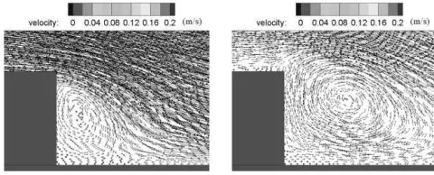
A comparison with similar sloshing settings but without the inside baffle indicated that the baffled tank could effectively reduce the water surface amplitude. This is due to that the existence of the baffle plate changed the natural frequency of the tank oscillation so as not to be much influenced by the external excitation frequency. Besides, the ISPH simulations also disclosed the existence of strong flow circulations and vortex evolutions inside the baffled tank, which is shown at two different times in Fig. 1. This has greatly dissipated the flow energy and thus reduced the water surface variations accordingly, while this phenomenon is hardly described by potential flow models.
Fig. 1 ISPH computed flow velocity field in a baffled tank sloshing.
Time histories of the water surface variation on left side of the tank are shown in Fig. 2, for the numerical results between ISPH and ALE simulations of Belakroum et al. (2010). In the figure, denotes the surface displacement from still water level. There is a good agreement between the two, indicating the accuracy of the ISPH modeling technique. However, it should be realized that much more complicated numerical algorithms have been implemented in the ALE, while ISPH adopted a much more straightforward formulation.
t (s)
/
a
0 2 4 6 8 10 12 14 16
-40 -20 0 20 40 60
80 ______ : ISPH
o o o o : Belakroum's result
Fig. 2 Time histories of water surface variation in a baffled tank, between ISPH simulations (solid lines) and ALE results (circles).
3.2 Force verification - solitary wave passing on a submerged obstacle
The study of solitary wave propagation and passing on a coastal
structure has attained great attention in recent years and become a hot topic in the coastal and offshore field. Earthquakes in the ocean often generate Tsunami waves and these waves are often simplified by the solitary wave models. For example, Chang et al. (2001) used a RANS model to study detailed vortex generations and evolutions for a solitary wave passing over a submerged rectangular obstacle. In this section we consider the solitary wave forces when it passes over a submerged underwater step. To verify the accuracy of ISPH model, we will compare the simulations with numerical results from NEWFLUME, which was developed by Lin and Xu (2006) to model complex wave-structure interaction problems using a RANS approach. The schematic model setup is shown in Fig. 3. An obstacle with height B = 0.114 m and length L = 0.381 m is submerged under the initial flow depth h= 2B. A solitary wave with height Hwave = 0.069 m
is generated from the offshore side. The ISPH used an initial particle spacing of 0.003 m and totally 101,574 particles were used in the computation. The ISPH computed time-dependent wave forces acting on the three faces (left, upper and right) of the obstacle are compared with the numerical results from NEWFLUME (Lin and Xu, 2006) in Fig. 4 (a) – (c), respectively. In the figures, solid lines represent the ISPH results and circles represent the NEWFLUME computations. It is shown that the numerical results between ISPH and NEWFLUME agree quite well to prove the pressure solutions and integrations over the solid surface are quite accurate in the ISPH. However, we do need to point out that in the present case, the solid structure is stationary but the computational situations can become much more complicated if the solid is in motion, in which the dynamic coupling is required.
t (s)
F
/
(0
.5
g
h0 2)
1.5 2 2.5 3
0.7 0.8 0.9 1
[image:4.612.34.294.263.373.2]
Fig. 3 Model setup of solitary wave Fig. 4 (a) Comparison of wave interaction with structure. forces on left face.
t (s)
F
/
(0
.5
g
h0 2)
1 2 3
-2.4 -2.2 -2 -1.8 -1.6
t (s)
F
/
(0
.5
g
h0 2)
1.5 2 2.5 3 3.5
-1 -0.9 -0.8 -0.7 -0.6
Fig. 4 (b) Comparison of wave Fig. 4 (c) Comparison of wave forces on upper face. forces on right face.
Fig. 5 shows the vortex generations behind the structure under the solitary wave passing by, and it shows that the vortex originates near the structure wall but moves further downstream with an increasing scale during the wave passing over.
[image:4.612.319.567.361.508.2][image:4.612.40.275.501.608.2] [image:4.612.326.566.573.670.2]
4 MODEL APPLICATIONS
4.1 Water entry of a cylinder
The water entry of a cylinder is always a benchmark application to test the numerical models. Usually the free surface deformation and cylinder kinematics are the main interest of investigation. In the ISPH model setup, we need to separate the circular cylinder boundary line into a series of straight-line segments to enable the mirror boundary treatment. The present simulation is based on the study of Colicchio et al. (2009) for their water entry process and more details are provided in the original paper. Their experimental study was conducted in a Plexiglas (40 mm thick) tank and the cylinder is made of stainless steel with a diameter of 30 cm. Its horizontal freedom is constrained. We consider a light cylinder entry with the density being 0.62 times of the water. In ISPH simulation, the particle spacing is d0 =0.006 m and
15,000 water particles are used. Colicchio et al. treated the cylinder as a free-falling body before its impact, while in ISPH an equivalent initial falling velocity of 2.55 m/s is given to the cylinder.
In Colicchio et al. (2009), the flow fields were measured by the Particle Image Velocimetry (PIV) technology. So these are used to compare with the present ISPH computations, as shown in Fig. 6. From the figure, it can be found that the water surface agreement is also quite satisfactory. At the beginning of the impact, high-speed flow region is near the impact point on the cylinder boundary, while in the later stage of the cylinder entry it moves on to the water surface. The difference between ISPH computation and PIV measurement is small but increases in the later stage as shown in Fig. 6 (c), which might be due to the PIV data noises near the surface area.
(a)
(b)
(c)
Fig. 6 ISPH velocity fields near cylinder surface (right), compared with PIV measurements (left) by Colicchio et al. (2009) at time t: (a) 0.004 s; (b) 0.154 s; and (c) 0.304 s, respectively.
The vertical movement of the cylinder is shown in Fig. 7, including the position and velocity variations through time, and is compared with the experimental data and numerical results from a two-phase Navier-Stokes solver based on approximated projection method (Colicchio et al., 2009). The figure illustrates the process of cylinder impacting on the water surface and entering, and then starting to float up with an upward velocity. It is shown that the comparisons between the ISPH and experimental results are quite desirable as well as with the numerical results based on the grid method of Colicchio et al. (2009). Moreover, an additional ISPH run is carried out with a double refined particle resolution of d0 = 0.003 m and the results are also
presented in Fig. 7. The consistency of two numerical results has indicated that the present coupled ISPH scheme has a good convergence property as well.
t (s)
v
er
ti
ca
l
d
is
p
la
ce
m
en
t
(m
)
0 0.5 1 -0.6
-0.4 -0.2 0 0.2 0.4
:exp data :ISPH d0=0.003 m
:ISPH d0=0.006 m :Grid-based results
(a)
t (s)
v
er
ti
ca
l
v
el
o
ci
ty
(m
/s
)
0 0.5 1 -3
-2 -1 0 1
:exp data :ISPH d0=0.003 m
:ISPH d0=0.006 m
:Grid-based results
[image:5.612.373.524.202.470.2](b)
Fig. 7 Vertical (a) position and (b) velocity of cylinder, compared with experimental and grid-based results of Colicchio et al. (2009).
4.2 Balance dynamics of a floating object
In this section we further investigate the balance dynamics of a floating object including its rotation. The aim is to check the accuracy of the model in calculating fluid force and moment. We use the study of Fekken (2004) for the balance of a floating object on the still water surface. Canelas et al. (2015) also investigated this problem using the WCSPH method. The schematic setup is shown in Fig. 8, in which a rectangular object is placed into the still water. The side length of the object is 0.05 m and 0.1 m, respectively, and the density of the object is half of the water density. The balance state under the gravity G and buoyancy is shown as the solid lines in Fig. 8. However, a small disturbance on the object could result in a small rotation (the dashed object in the figure) since the moment on the left (Bl) and right (Br)
[image:5.612.37.281.357.670.2]the solid object depends on the parameters of the object.
[image:6.612.350.537.177.372.2] [image:6.612.113.216.185.327.2]Although the final state of the floating object depends on the balance of the moment and shape of the body, the dynamic process to reach the new balance position is quite interesting. Following the descriptions of Canelas et al. (2015), a numerical water tank that is 1.0 m long and 0.1 m deep is used. The ISPH computational particle spacing is 0.0033 m and totally 7,965 particles are used in the simulation. The side length of the rectangular object is 0.05 m and 0.1 m and its initial immersion depth is 0.05 m, which is on the balance position under the actions of gravity and buoyancy. The solid block is placed in the middle of the water tank and the centre of gravity is located at the still water surface in the beginning of the computation.
Fig. 8 Schematic setup of floating object on still water surface.
Following Fekken (2004), an initial small disturbance moment was imposed so the solid object motion was activated. As the inertia of the solid object can lead to its oscillations around the balance angle in the water and result in the surge wave generations, which will be reflected by the solid boundaries and then disturbs the motion of the block, an adequate numerical damping must be used to eliminate the surge waves. This sponge layer is placed on both sides of the flume to eliminate the reflected waves. The length of the damping layer in the present study is 0.3 m and near the two sidewalls. As shown in Fig. 9 (a), after a small disturbance the block starts to roll and the vortex generated near the solid corner can be found. At time t = 1.0 s, a strong surge wave is generated with intensive local wave breakings. The maximum velocity is found near the edge of the block and on the wave front. These surge waves propagate to the flume end and are effectively eliminated by the damping layers. The floating object will roll around its balance angle during which the kinetic energy is gradually dissipated by the water. In Fig. 9 (b) at t = 3.4 s, the block is still rolling on but the amplitude becomes much smaller, and the flow field nearby is almost quasi-stationary. With the help of the sponge damping layer, the flume length could be very short and this saves considerable CPU expenses.
To quantitatively verify the ISPH computations, the time history of deflection angle of the block during its rotational motions is shown in Fig. 10, compared with the numerical results of Fekken (2004). In order to adapt to the time series of the Fekken, the phase of present ISPH results has been shifted. From the figure, it is seen that the rolling of the object is strongly reduced in the first two periods and most of the kinetic energy is transformed to the water, which is then dissipated by the wave breaking process and damping layer, but a very small oscillation can still last for a long time. The agreement between the ISPH and Fekken (2004) results is quite satisfactory, except that there is a slight phase difference in the later stage of the simulation.
Another convergence test with refined particle spacing of 0.00166 m has also been carried out and the results are shown in Fig. 10 as the
dashed line. It is shown that the discrepancy between the two particle resolutions is tiny, demonstrating the convergence of the ISPH computations. The desktop used in our study is equipped with Intel i5-3470 CPU and 4GB memory. In the first run with lower particle resolution, the total CPU cost was 0.5 hour for a 5.0 s simulation. In the second higher resolution test, the 31,620 water particles used in the simulation increased the calculation time by 20 times.
Velocity (m/s): 0 0.04 0.08 0.12 0.16 0.2 0.24 0.28 0.32 0.36 0.4 0.44 0.48
(a) t = 1.0 s
[image:6.612.372.522.408.538.2](b) t = 3.4 s
Fig. 9 Flow field near floating structure during dynamic rolling.
t (s)
d
ef
le
ct
io
n
an
g
le
(d
eg
)
0 1 2 3 4 5 -100
-50 0
:Fekken (2004) :ISPH (d0=0.0033m)
:ISPH (d0=0.00166m)
Fig. 10 Time history of deflection angle in rotational dynamics.
Moreover, another two cases of the floating block with density being 0.5 and 0.25 times of the water have also been studied. The ISPH computed final balance angles are 45° and 63.5°, respectively, which are consistent with the theoretical values of Fekken (2004). In Canelas et al. (2015), due to the inherent nature of their SPH scheme, the start of the rolling process is random, while in our ISPH simulation a small disturbance is used. This small disturbance shall not affect the final balance of the structure, despite that the rolling directions might be changed in a different way. The fundamental structure dynamic process should be globally more or less similar.
G Bl
5. CONCLUSIONS
This study discussed the ISPH model applications in the coastal and offshore hydrodynamic field for the fluid-structure interactions. The coupled model has been systematically validated by a series of benchmark tests. Firstly a simple sloshing motion is computed to demonstrate the moving boundary treatment. Secondly in the force verification, the surface forces are integrated and compared with other numerical results, which showed that the external forces have been accurately obtained on all sides of the obstacle. The model is then applied to two more complex fluid-structure coupling problems. In the falling cylinder case, satisfactory agreement has been found in the cylinder motion, velocity field and free surface deformation between the ISPH simulations and PIV measurements. The model is finally applied to the rotational dynamics of a floating object. In the simulation, the rotation freedom is released and the time history of deflection angle is compared with the documented data. The wave damping layer is also used for the surge wave eliminations. The numerical results have showed that the proposed ISPH model is able to disclose complex flow features in the spatial domain, and demonstrated its great potentials to model various fluid-structure interaction problems in the engineering practice. These application cases provided a robust benchmark test for the coupled SPH models.
ACKNOWLEDGEMENTS
This research work is supported by the Research Fund for the Doctoral Program of Higher Education of China (20120181110084), China Postdoctoral Science Foundation (2014M552358) and Open Research Fund of the State Key Laboratory of Hydraulics and Mountain River Engineering, Sichuan University (SKHL1409).
REFERENCES
Belakroum, R, Kadja, M, Mai, TH, and Maalouf, C (2010). “An Efficient Passive Technique for Reducing Sloshing in Rectangular
Tanks Partially Filled with Liquid,” Mech Res Commu, 37, 341-346.
Bøckmann, A, Shipilova, O, and Skeie, G (2012). “Incompressible
SPH for Free Surface Flows,” Comput & Fluids, 67, 138-151.
Canelas, RB, Dominguez, JM, Crespo, AJC, Gomez-Gesteira, M, and
Ferreira, RML (2015). “A Smooth Particle Hydrodynamics
Discretization for the Modelling of Free Surface Flows and Rigid Body Dynamics,” Int J Numer Meth Fluids, 78, 581-593.
Chang, KA, Hsu, TJ, and Liu, PLF (2001). “Vortex Generation and Evolution in Water Waves Propagating over a Submerged
Rectangular Obstacle, Part I. Solitary Waves,” Coast Eng, 44, 13–
26.
Colicchio, G, Greco, M, Miozzi, M, and Lugni, C. (2009).
“Experimental and Numerical Investigation of the Water-entry and Water-exit of a Circular Cylinder,” Proc 24th Int. Workshop on Water Waves and Floating Bodies, Zelenogorsk, Russia.
Cummins, SJ, and Rudman, M (1999). “An SPH Projection Method,” J
Comput Phys, 152, 584-607.
Fekken, G (2004). Numerical Simulation of Free Surface Flow with Moving Rigid Bodies, PhD thesis, University of Groningen.
Gotoh, H, Khayyer, A, Ikari, H, Arikawa, T, and Shimosako, K (2014).
“On Enhancement of Incompressible SPH Method for Simulation of
Violent Sloshing Flows,” Appl Ocean Res, 46, 104-115.
Gotoh, H, Shibahara, T, and Sakai, T (2001). “Sub-Particle-Scale
Turbulence Model for the MPS Method - Lagrangian Flow Model
for Hydraulic Engineering,” Comput Fluid Dyns J, 9, 339-347.
Hwang, SC, Khayyer, A, Gotoh, H, and Park, JC (2014).
“Development of a Fully Lagrangian MPS-based Coupled Method for Simulation of Fluid–structure Interaction Problems,” J Fluids & Strucs, 50, 497-511.
Khayyer, A, Gotoh, H, and Shao, SD (2008). “Corrected
Incompressible SPH Method for Accurate Water-surface Tracking in Breaking Waves,” Coast Eng, 55(3), 236-250.
Khayyer, A, Gotoh, H, and Shao, SD (2009). “Enhanced Predictions of Wave Impact Pressure by Improved Incompressible SPH
Methods,” Appl Ocean Res, 31, 111-131.
Koshizuka, S, Nobe, A, and Oka, Y (1998). “Numerical Analysis of Breaking Waves Using the Moving Particle Semi-implicit method,” Int J Numer Meth Fluids, 26, 751-769.
Lin, PZ, and Liu, PLF (2004). “Discussion of “Vertical Variation of the Flow across the Surf Zone” [Coast Eng 45 (2002) 169–198],”
Coast Eng, 50 (3), 161–164.
Lin, PZ, and Xu, WL (2006). “NEWFLUME: A Numerical Water
Flume for Two-dimensional Turbulent Free Surface Flows,” J Hydr Res, 44, 79-93.
Lind, SJ, Xu, R, Stansby, PK, and Rogers, BD (2012).
“Incompressible Smoothed Particle Hydrodynamics for Free-surface Flows: a Generalised Diffusion-based Algorithm for Stability and Validations for Impulsive Flows and Propagating Waves,” J Comput Phys, 231(4), 1499-1523.
Liu, MB, Shao, JR, and Li, HQ (2014a). “An SPH Model for Free
Surface Flows with Moving Rigid Objects,” Int J Numer Meth
Fluids, 74, 684–697.
Liu, X, Lin, PZ, and Shao, SD (2014b). “An ISPH Simulation of
Coupled Structure Interaction with Free Surface Flows,” J Fluids &
Strucs, 48, 46-61.
Liu, X, Lin, PZ, and Shao, SD (2015). “ISPH Wave Simulation by Using an Internal Wave Maker,” Coast Eng, 95, 160-170.
Monaghan, JJ (1994). “Simulating Free Surface Flow with SPH,” J
Comput Phys, 110, 399-406.
Moyo, S, and Greenhow, M (2000). “Free Motion of a Cylinder
Moving below and through a Free Surface,” Appl Ocean Res, 22,
31–44.
Oger, G, Doring, M, Alessandrini, B, and Ferrant, P (2006). “Two
-dimensional SPH Simulations of Wedge Water Entries,” J Comput
Phys, 213, 803-822.
Omidvar, O, Stansby, PK, and Rogers, BD (2012). “Wave Body Interaction in 2D Using Smoothed Particle Hydrodynamics (SPH)
with Variable Particle Mass,” Int J Numer Meth Fluids, 68, 686-705.
Ren, B, He, M, Dong, P, and Wen, HJ (2015). “Nonlinear Simulations of Wave-induced Motions of a Freely Floating Body Using WCSPH
Method,” Appl Ocean Res, 50, 1-12.
Shao, SD, and Lo, EYM (2003). “Incompressible SPH Method for Simulating Newtonian and Non-Newtonian Flows with a Free
Surface,” Adv Water Resour, 26, 787-800.
Vandamme, J, Zou, QP, and Reeve, DE (2011). “Modeling Floating
Object Entry and Exit Using Smoothed Particle Hydrodynamics,” J
Wtry Port Coast Ocean Eng, 137, 213-224.
Violeau, D, and Leroy, A (2015). “Optimal Time Step for
Incompressible SPH,” J Comput Phys, 288, 119-130.
Wei, G, and Kirby, JT (1995). “Time-dependent Numerical Code for Extended Boussinesq Equations,” J Wtry Port Coast Ocean Eng, 121, 251–261.
Yildiz, M, Rook, RA, and Suleman, A (2009). “SPH with the Multiple
Boundary Tangent Method,” Int J Numer Meth Eng., 77, 1416-1438.