Rochester Institute of Technology
RIT Scholar Works
Theses
Thesis/Dissertation Collections
1-1-1994
The Simulated Bread Board Imaging system: A
Study of computer simulation as an engineering
tool
Gregory R. Conway
Follow this and additional works at:
http://scholarworks.rit.edu/theses
This Thesis is brought to you for free and open access by the Thesis/Dissertation Collections at RIT Scholar Works. It has been accepted for inclusion
in Theses by an authorized administrator of RIT Scholar Works. For more information, please contact
Recommended Citation
The Simulated Bread Board Imaging System:
A Study of Computer Simulation as an Engineering Tool
Gregory R. Conway
•
Computer Science Department, Rochester Institute of Technology, Rochester, NY
Joseph C.
Wilson Center for Research and Technology, Xerox Corporation, Webster, NY
A thesis, submitted to The Faculty of the Computer Science Department at RIT,
in partial fulfillment of the requirements for the degree of Master of Science in Computer Science
.
Approvals:
Allen Ted Retzlaff
Dr. Allen Ted Retzlaff, Xerox Corporation
Date
John Shaw
Dr. John Shaw, Xerox Corporation
Date
Peter G. Anderson
Dr. Peter Anderson, Rochester Institute of Technology
Date
Table
of
Contents
Section
Page Number
Abstract
Chapter
1
-Introduction
Introduction 5
Images 5
Visual artifacts 5
Modeling and simulation 6
Users and customers 1
Chapter
2
-History
andPerspective
Introduction 9
The history of modeling and simulation 9
Precursors to the SBBI system 11
Human vision 11
The Xerox Image Processing toolset 12
The Xerox Image Metrics toolset 13
The Xerox Color Calibration toolset 13
The Xerox Image Simulation Environment 13
The Modular Simulation Package 14
Thermal Ink Jet (TIJ) printhead simulation 14
Full-page image simulation 14
The SBBI System An overview 15
Chapter 3
-The
Design
andImplementation
ofthe SBBI System
Introduction 21
Assumptions 21
Build for the trained user 21
Leverage existing components 22
Standard platform 22
Standard language 22
External printer service vendors 22
A brief tour of the development process 23
Understanding the SBBI data structures 23
SBBI client/server design 23
The switch to X Windows 25
Shell scripts 25
Client self-configuration 25
Looping and filing 26
Server self-configuration 26
Cleanup and testing 2 6
The Architecture of the SBBI System 27
The SBBI server 2 9
Startup 29
Client connections 29
Running the script 32
The SBBI server file naming conventions 33
The SBBI Client 33
Startup 33
The main window 34
Generating the output file(s) 36
Xerox Image Metrics 39
Future expansion Acknowledgments . Dedication
43 44
Appendix
A
-The SBBI
User's Manual
Introduction
Starting the SBBI system Starting the SBBI server Starting the SBBI client Using the SBBI system
Understanding visual artifacts
Using the SETUP dialog box to configure the prints Input image file name
Output image file name Number of prints to generate Resolution of output medium Compress output image file
Scale preview image to what percentage Output format
Using Visual Artifacts
Applying an artifact to the input image Editing an artifact'
s properties
Removing an artifact from the input image Removing all artifacts from the input image Inserting an artifact into the middle of the
programmed artifacts list box Filing
Saving the current set of applied artifacts Retrieving an old Set of applied artifacts Returning to the main window
Generating the output file(s) Using the output file(s) Configuring the SBBI system
Configuring the client Configuring the server
45 45 46 47 49 50 51 51 51 52 52 52 53 53 54 55 55 55 55 56 56 56 56 57 57 57 58 58 60
Appendix B
-The
SBBI Visual Artifacts
Introduction
The SBBI system visual artifacts
61 61
Appendix
C
-Sample SBBI Shell Script
Introduction
Sample shell script
63 63
Appendix D
-Sample Prints
Introduction
Print 1 (Frequency = 100, Amplitude = 0) Print 2 (Frequency = 100, Amplitude = 2) Print 3 (Frequency =
100, Amplitude = 4) Print 4 (Frequency = 100, Amplitude =
6) Print 5 (Frequency = 100, Amplitude = 8) Print 6 (Frequency = 100, Amplitude = 10)
Abstract
A
software system wasdeveloped
to
aidin
the translation
of customer printquality
requirementsinto formal
design
specificationsduring
the
development
of new printers and copiers.The
systemis
designed
to
allowthe
userto
generate a series of prints with variousdeviations,
or visualartifacts,
introduced into
them.
These
artifacts simulatethe
effects ofdesign
considerations onthe
expected output atthe
image
outputterminal.
The resulting
prints canbe
usedto
incorporate
customerfeedback
and requirementsearly
in
the
development
cycle.In
sodoing,
it is
expectedthat the
needfor
hardware
prototyping
canbe
reduced or eliminated.The
resultis
a product whichis
costeffective,
markettimely,
and customer oriented.Computing
Reviews Classification Information
Chapter
1
Introduction
A
computer programhas been
developed
to
aidin
the
determination
of copier andprinter
design
requirementsearly
in
the
productdevelopment
cycle.The
programis
known
asthe
Simulated
Bread Board
Imaging
(SBBI)
system.The
softwareis
intended
to
mimicthe
output characteristics of printers and copiers.The
goalis
to
simulate
the
effect ofdesign
configurations onthe
printquality
ofthe
outputimage. This
allows customersto
comment onthese
image
quality
effectsbefore
significant resourceshave
been
spentdesigning
andbuilding
prototypehardware.
Once
the
userhas
workedwith
the
customerto
determine his
orher
requirements, the
information is
sentto
Xerox
engineers,
whotranslate
these
requirementsinto formal design
specifications.Chapters
2
and3
discuss
the
historical,
business
andtechnical
aspects ofthe
SBBI
system.The
remainder ofthis
chapterlays
the
groundworkfor
those
chaptersby
defining
severalkey
concepts andterms.
1.1
Images
An image
is
adigital
computer graphicsfile
containing
text
or pictures.The
SBBI
program reads animage
asinput,
modifiesthe
image
according
to
the
user'sspecifications,
and writesthe
resulting
image
as output.The
input image
correspondsto
the
paper placedonthe
glasscopying
surface of a copier orthe
rawdata
stream sentto
aprinter.
The
outputimage
correspondsto the
copy
producedby
the
copier orthe
paper print producedby
the
printer.1.2 Visual Artifacts
andProperties
A
visual artifactis
any
deviation between
the
input image
andthe
outputimage.
These
deviations
affectthe
appearance orquality
ofthe
printin
some quantifiablefashion.
Notice
that
nothing
in
the
definition
of visual artifactimplies
that the
artifactmust
have
adetrimental
effect onthe
image
appearance.Some
customersmay
find
thatthe
inclusion
of certain visual artifactsactually improves
the
outputimage.
Many
vendors provide software and
hardware
solutionsfor
customersseeking
to
improve
or enhanceimages.
The SBBI
system couldbe
used as atool to
aidin
the
development
of such solutions.However,
the
SBBI
systemis
typically
usedto
help
engineersminimizethe
introduction
of visualartifacts,
sothat
the
output printbecomes
afaithful
reproduction
(within
the
confines ofthe
customer'srequirements)
ofthe
input image.
referred
to
asbanding
(see Appendices
B
andD).
The
effects ofbanding
canbe
reducedby
incorporating
better
motors and paperhandling
mechanisms.The
inclusion
ofthis
additional
hardware, however,
may
presentengineering
obstaclesthat
drive
the
costbeyond
the
customer's range.Therefore,
it is important
to
understandexactly how
much of each artifactthe
customeris
willing
to accept,
andhow
muchhe
or sheis
willing
to
spendto
remove or minimizethe
remainder.This information
is
then
givento the
design
engineers who candevelop
the
systemin
accordanceto the
customer's requirements.In
this sense, the
SBBI
system supportsthe
Total
Quality
Management
initiative
atXerox.
Appendix
B
describes
each ofthe
visual artifactscurrently
supportedby
the
SBBI
system.A property
is
any
piece ofinformation
neededto
describe
andimplement
an artifact.For
example, the
banding
artifacthas
two properties, the
frequency
ofthe
bands
(which determines how
many
bands
will appear per unitdistance)
andthe
amplitude ofthe
bands (which determines
the
prominence of eachband).
The SBBI
systemimposes
nolimit
onthe
number of artifactsit
cansupport,
or onthe
number of properties each one ofthose
artifactsmay
require.1.3
Modeling
andSimulation
The
SBBI
systemis
a casestudy
in
two related,
but
separate,
fields
of study:modeling
and simulation.While
these two
words are often usedinterchangeably
in
the
computer sciencefield, they
shallbe
restrictedto
a more precisedefinition for
the
purposes ofthisdiscussion.
The American Heritage
dictionary1defines
a model as"a
tentative
description
of a system ortheory
that
accountsfor
all ofits known
properties."
It
defines
simulate as"to
have
ortake
onthe appearance,
form,
or soundof;
imitate."A
modelis
a set ofequations,
theories,
anddata
that
describe
a system.A
simulationis
the exerciseofa model.The
distinction
between
a model and a simulationis important because
the
SBBI
program contains elements ofboth.
The modeling
componentincludes
the
determination
ofhow
to
understand andmathematically
expressthe
presence and character ofvisual artifactscommonly
found
in
printers.This
is
anon-going
researchinitiative
atmany
companies,
including
Xerox.
Most
ofthe
modeling in
the
SBBI
system camefrom
previous research initiatives2-3'19The
bulk
ofthe
workdescribed in
this
paperis
thedevelopment
of a simulatorthat
incorporates
these
modelsto
simulate a printengine.The
intent
ofthis
project wasnotto
modelthe
physicalbehavior
ofvarious printcustomer,
the
scientificexplanationfor
visual artifactsis
not asimportant
asthe
fact
that
the
artifact exists at allin
the
outputimage.
Therefore
it is
sufficientfor
the
systemto
present
to the
customer a realisticinterpretation
ofthe
outputimage,
without concernfor
modeling
the
mechanical and physical processesthat
createdthe
image.
1.4 Users
andCustomers
The
useris
the
individual
who sits atthe
computerconsole andinteracts
withthe
SBBI
system.Presumably,
the
user understandsthe
visual artifacts and whatdesign
Chapter 2
History
and
Perspective
This
chapter providesthe
reader with ahistorical
perspective onthe
SBBI
system.The
use ofmodeling
and simulation as scientific andbusiness
tools
is
discussed,
followed
by
an explanation ofthe
specificXerox
initiatives
that
eventually
lead
to the
SBBI
system.Finally,
an overview ofthe
SBBI
systemis
providedthat
highlights its
unique advantages overthese
previousinitiatives,
andintroduces
the
readerto
its features
and capabilities.2.1
The
History
ofModeling
andSimulation
Modeling
and simulation goback
to
atime
long
before
modern computers.Scientific
modeling
dates back
to the
very
beginnings
of scientificthought.
In
fact,
[image:11.574.216.362.385.452.2]science
itself is
the
effort of mankindto
apply
reason and mathematicsto
describe,
in
anorderly
fashion,
the
workings ofthe
world around us.Every
scientifictheory
or equation ever expressedis
a model of some aspect of our universe.For
example,
Ohm's law is
a model ofthe
behavior
of a simple electronicdevice known
asthe
resistor.(Ohm's law
statesthat the
voltage across aresistor,
V,
is
equalto the
product ofthe
currentpassing
through the resistor,
I,
andthe
resistance ofthe resistor,
R.
See
Figure 2-1).
Figure 2-1
Ohm's
law
as a scientificmodelModels
aremerely
predictions and approximations ofthe
behavior
of some object or system.Before
a model canbe
accepted,
it
mustbe
tested.
Historically,
this
has been
done
using
one oftwo techniques:
experimentation or simulation.Experimentation
is
the
direct study
ofthe
actual object or systemto
seeif it
correspondsto the
model.For
example, to
determine
if
Ohm's law does
in
fact describe
the
behavior
of simpleresistors,
scientistshave
measuredthe three
variables expressedin Figure 2-1
and checkedthe
results againstthe
model.However,
experimental verificationis
not always practical.For
example,
it is
difficult
to test
models aboutthe
behavior
of particles onthe
edge of ablack
hole,
because
humans
cannot yet reachblack holes.
It may be
too
dangerous
to
study
otherSimulation
is
the
exerciseof a model withoutdirect
useofthe
object or systemthe model represents.Simulation
does
nothave
to
be
carried out on a computer(storms
canbe
simulatedin
a windtunnel,
anddummies
simulatehuman
beings in
automobilesafety
testing).
However,
computershave become
anincreasingly
valuabletool
for
conducting
simulations.
Computers
bring
a wide range ofbenefits
to
bear
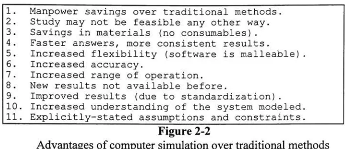
onsimulationproblems.Some
ofthe
benefits
of computersimulation,
summarizedin
Figure
2-2,
have
already
been identified in
other research efforts4.1. Manpower savings over traditional methods. 2.
Study
may not be feasible any other way. 3. Savings in materials (no consumables). 4. Faster answers, more consistent results.5. Increased
flexibility
(software is malleable). 6. Increased accuracy.7. Increased range of operation. 8. New results not available before.
[image:12.574.117.461.193.342.2]9. Improved results (due to standardization) . 10. Increased understanding of the system modeled. 11. Explicitly-stated assumptions and constraints.
Figure 2-2
Advantages
of computer simulationovertraditional
methodsEvery
computer simulationis designed
to
meet some objective.The
objectiveis
the
ultimate answer(or answers)
the
userhopes
to
acquire withthe
aid ofthe
simulator.The
answer mightbe
as simple as atest
ofOhm's
law,
or as complex as astudy
ofthe
[image:12.574.121.456.498.587.2]feasibility
oflanding
a space craft onMars.
The
objective of most simulation experimentsbelongs
to
one offour
major categories5.These
categories are shownin
Figure 2-3. The SBBI
systemis
an example ofthe
first
category
ofsimulation,
because it
is designed
to
answer what//"questions regarding
print enginedesigns
(e.g.,
"what
effectwould
it have
onthe
customer's perceptionif
the
frequency
ofthe
banding
is
increased?").
1. Comparison of a finite number of strategies regarding an individual real-life problem. 2. Simulation for
developing
functionalrelationships.
3. Use of simulation for validating and evaluating newly developed analytical methods.
4. Use of simulation for educational purposes.
Figure 2-3
Objectives
of computer simulationComputer
simulationshave
existed sincethe
earliestdays
ofdigital
computers,
but it
was notuntilthe
1960s
and1970s
that
they
began
to take
onaprominentrole as a viabletool
for
science andbusiness.
While
basic
simulationprincipleshad been
appliedfor
decades,
it
was not untilthis time that
computers grew powerful enoughto
handle
complex models.With
the
advent ofthese
new computers camethe possibility
ofextracting
scientific andbusiness
valuefrom
computer simulation techniques.One
ofthe
first
uses of computer simulation was as abusiness
tool
for
corporateAmerica5.
Executives began
to
use computer simulationsto
help
determine
the
optimalway
to
spend
time,
money,
and resources.The
software gavethem
the
opportunity
to
explorebusiness
scenarioscompletely
without concernfor
waste orfailure.
In
this
way
the
executive could
determine
the
option mostlikely
to
yieldthe
desired
results.The
use of computer simulation as anengineering
tool
has
alsobeen
evolving
for
many
years.Engineers
specializein
building
real-world systemsfrom
precise mathematicaldescriptions.
These
mathematicaldescriptions
constitute models ofthe
actual system.When
incorporated into
computersimulations, these
models provide a valuabletool to
help
engineerstest
anddevelop
systems.Simulation
canbe
usedin
every
step
ofthe
development
processto
ensurethat the
final
productis
evolving
to
meetthe
original specifications.The
Boeing
Corporation
has
used simulationeffectively
to
design
complex airplane surveillance systems10as well as
to
develop
large
portions ofthe
777
aircraft18.Studies have
proventhat
simulation candetect
problemsearly
in
the
design
phase,
reducing
cost overruns and productdelivery
delays11.
Some
engineershave
used computer simulationsto
develop
systems with optimaldesigns12.
The SBBI
systemis different from
such studiesin
the
way
that
it brings
simulation
to
engineers.Rather
than tell them
if'they
aredoing
their
job
right, the
SBBI
systemis designed
to
help
them
determine how
to
do
their
job
right.In
this case,
doing
the
job
right meansdesigning
andbuilding
a print enginethat
meetsthe
customer's requirementsfor
printquality
the
first
time.
Thus,
the
SBBI
systemis
aproactive,
ratherthan
reactive, engineering
tool.
2.2 Precursors to
the
SBBI
systemThe
SBBI
systembenefited from
alegacy
of simulationtools
appliedto
engineering
tasks2'3'13'14'15-16-18.
Xerox
has
been
relying
increasingly
on computer simulationsto
reduce costand solve problemsfor
severaldecades. This
sectiondescribes
several ofthe
studies and programsinitiated
previously
that
contributedto the
design
ofthe
final
SBBI
program.2.2.1
Human Vision
Studies
7"A
pictureis
worth athousand
words."-
Anonymous
Appendix
D
shows a series of prints with a progressive amount ofbanding
introduced.
(Recall
that
banding
is introduced
whenthe
paperdoes
not move at auniform speed
through the
printengine.)
The first
print,
labeled
Banding
Example:
f
=100
a =0,
showsthe
base
print asit
might appearfrom
a perfect copier(in
this case,
f
refersto the
frequency
ofthe
banding,
and a refersto
the
amplitude).The
secondprint,
labeled
Banding
Example:
f
=100
a =image.
Notice
the
impact
that
eventhis
small amount ofbanding
has
onthe
overall perceivedquality
ofthe
print.This
is
a result ofthe
way
humans
see.Human
visionis
only
nowbeginning
to
be
understood.While
humans
enjoy
the
benefit
offive
senses,
up
to
90%
ofhuman
perception comesdirectly
from
sight.For
acompany like
Xerox,
whose corebusiness is
printing
andimaging,
this
percentageis
crucial.Humans
are capable ofdiscerning
extremely
smalldiscrepancies in
visualmaterial.
The
level
at which visualdeviations
canbe
detected,
andthe
affect ofthose
deviations
onthe
viewer's opinion ofthe
image,
arehighly
subjective.Not
all viewers reactthe
sameway
to the
same visualinformation.
These
divergent
perceptions canbe
attributed notonly
to the
differences between
the
subject'sbrains,
but
also onthe
intended
use ofthe
image.
For
example,
it
may
be
acceptablefor
a printdestined
for
afamily
albumto
have
some small amount of graininess.However,
the
samelevel
of graininessmay
be
unacceptablefor
ahigh
altitudemilitary
reconnaissancephotograph,
orthe
cover of afashion
magazine.For
this reason,
it is
criticalto
incorporate
the
customer's subjective reactionto
sample printsbefore
the
final
product goesinto
production.2.2.2
The Xerox
Image
Processing
Toolset
14The Xerox Image
Processing (XIP)
toolset*is
a set ofimage
processing
tools
developed
atXerox.
The XIP
tools
comein
two
standard varieties: executablelibraries
that
canbe linked
with user programs(usually
writtenin
C,
althoughany
programthat
follows
the
C calling
convention couldpresumably be
linked
withXIP
modules),
and stand-alone executable programs(capable
ofbeing
incorporated
into
a UNIX shellscript).
This
makesit
possibleto
build
programsutilizing XIP
in
either compiled(C)
orinterpreted
(UNIX
shellscript)
format.
XIP
is both
a collection ofexisting
imaging
routines and a platform
for
the
development
ofnewimaging
routines.The
XIP
libraries
containfunctions for
reading
andwriting images
in
avariety
offormats
andtranslating
them
into
asimple,
easily
manipulated,
internal format.
XIP
routineshave been
writtento
introduce
each ofthe
visual artifacts supportedby
the
SBBI
system3,
as well asmany
others.XIP
calls areusually
sandwichedbetween
two
othercalls,
onethat
readsdata
files
in
some externalformat
(such
asgif,
tiff,
orjpg)
and produces a new versionin
theinternal
format;
and onethat
does
the
reverse.Figure 2-4
illustrates
a simpleXIP UNIX
shell script.The
XIP
systemis
anon-going
research projectwithinXerox.
*
Severalofthe toolsetsused
by
theSBBIsystem are still under activedevelopment
atXeroxandare consideredXeroxprivatedata
Toprotectthecompany'sinterests,
thenames ofthese toolsetshave been alteredfor
thepurposes ofthisdiscourse.
Thefollowing
toolsets,
referencedin
this paper,areknownby
differentnames withinXerox: The Xerox ImageProcessing
Toolset(section
2.2.2),
theXerox Image Metrics Toolset (section2.2.3),
theXerox ColorCalibration
Toolset (section2.2.4),
theXeroxImage Simulation Environment (section2.2.5),
andtheModularSimulation
Package (section 2.2.6).read_jpg
foo.jpg
|
scale 10.0|
rotate 90.0|
write_tiff foo.tifFigure 2-4
Sample XIP
script2.2.3 The Xerox Image Metrics
Toolset15The Xerox
Image Metrics
(XIM)
toolset
is
a set ofimaging
routinesdeveloped
atXerox
for
studying
the
quality
of printedimages.
The
toolset
is designed
to
objectively
measure
the
quality
of a printsaccording
to
certainpredefinedmetrics.The XIM
package providesdistributed
services,
as well as alibrary
of metrics routines.The SBBI
systemdoes
notcurrently
useXIM,
althoughhooks for its
introduction
areincluded. XIM
couldbe
used,
for
example, to
performthe translation
of subjective customer commentsinto
objective print
quality
metrics,
orto
produceaself-tuning
system(see
section4.3).
2.2.4 The Xerox Color Calibration Toolset
l6The Xerox Color Calibration
(XCC)
toolset
is
a set ofroutinesfor
handling
colorcalibration.
The
toolset
provides routinesfor
translating
color schemesfrom
oneencoding
into
another,
andproducing
standard color calibrationimages
suitablefor
various classes of printers.The SBBI
system usesXCC features
to
perform color separation and management.The XCC
tools
read and writethe
sameinternal format
graphicsfiles
asthe
XIP
routines.2.2.5
The Xerox Image Simulation
Environment89Several
years agoXerox
Webster Research Center (now
known
asthe
Joseph
C.
Wilson
Center for
Research
andTechnology)
began
workon aunifying
infrastructure for
the
modeling
and simulation ofimage
outputterminals
(printers
and copiers).The
goalof
the
system wasto
develop
an environment ofhardware
and softwarethat
wouldbecome
the
basis for
allfuture
models and simulations of print engines withinXerox
corporate research.
That
simulation environment was not applicableto this
particularproject,
sinceit
wasdirected
atstudying
physical characteristics of print engines.The
system was
designed
to
facilitate
the
study
ofhow
the toner
is laid down
onthe paper,
andtiming
the
movement ofthe
paperfrom
componentto
component.Because
ofthe
extraordinarily
fine level
ofdetail involved in
suchsimulations,
a greatdeal
ofprocessor power andtime
may
be
required(depending,
ofcourse,
onthe
actual model andthe
size ofthe
image).
For
example,
atypical
Sun
Sparc computer might require anhour
or moreto
modelthe
printing
of animage
afew
square millimetersin
area.The
goal ofthe
SBBI
system wasto
provide a viableengineering
tool
for
the
full-page
images.
The
systemis
designed
to
be
capable of rapidfeedback
and analysis.For
example,
the
SBBI
system provides an on-screen preview modethat
allowsthe
user to experiment withthe
values of propertiesbefore
producing
the
final
set of prints.If
the
SBBI
systemis
to
be
responsive under suchcircumstances,
it
mustbe
capable ofproducing
outputimages
within afew
minutesto
anhour.
The Xerox
image
simulation environmentwasnotintended
to
handle
this type
of rapid simulation.While
these tools
were notultimately
incorporated into
the
SBBI
system, the
Xerox
Image
Simulation
Environment
projectdoes illustrate
the
fundamental importance
Xerox
places onusing
simulation as a means ofadding
valueto
research anddevelopment.
In
this regard,
it laid
some ofthe
groundworkfor later
applications ofcomputer
simulation,
including
the
SBBI
system.2.2.6 The Modular Simulation
Package20-21A FORTRAN
program wasdeveloped
atXerox
in
the
early 1980s
for
modeling
print engines.
The
system wasdesigned
to
allowthe
userto
plug in FORTRAN
modulesthat
described
the
behavior
of various mechanical subsystems.These
modelsmathematically described
the
inputs,
outputs,
and operation ofthe
subsystem.The
system was
designed
to
configureitself
atstartup
andto
dynamically
attach each subsystemthat
wasto
become
part ofthe
simulation.Like
the
Xerox
Image Simulation
Environment,
the
Modular Simulation Package
was
designed
to
simulatethe
system at a physicallevel.
For
this reason,
it
required along
time to
execute.Furthermore,
because
the
models were writtenin FORTRAN
the
systemwould,
nothave integrated
well withthe
UNIX
andC libraries
usedby
the
SBBI
system.The Modular Simulation Package
andthe
SBBI
system aresimilar,
however,
in
that
both
utilize
self-configuring
elementsto
enhancesystemoperation(see
section2.3).
2.2.7
Thermal Ink Jet
(TIJ)
Printhead
Simulation2A
computer simulation wasdeveloped
atXerox
in
1992
for
the
study
ofthermal
ink jet
(TIJ)
printheads.The
simulation centered on a problemquality
testers
werehaving
with someinitial
versions of athermal
ink jet
printhead.A
computer model wasdeveloped
to
mimicthebehavior
ofthe
printheadin
orderto
study
the
problem.The
TIJ
simulator wasdesigned
to
read aninput image
and convertit into
standardXIP
internal format.
In
the process, the
image
wouldbe
rasterized and some color correction wouldbe
applied.The
system wouldthen
apply
several customXIP
routinesto
simulatethe
operationofthe
TIJ
printhead.The resulting images
were stored andprintedfor
analysis.The
images
producedby
this
simulation proved usefulin
determining
the
cause ofthe malfunction.
Eventually,
the
solutiondeveloped
withthe
aid ofthe
simulator wasincorporated back
into
the
production version ofthe
printhead.While
this
project wasoriginally begun
to
study
a specificproblem, the
success ofthe
effortlead
to
a moregeneral approach
(see
section2.2.8).
Many
ofthe
elements ofthis
first
simulation werecarried over
into
this
nextversion,
andfrom
there
into
the
SBBI
system.2.2.8 Full-Page Image
Simulation3The
full-page
image
simulation system wasdeveloped
as a continuation ofthe
thermal
ink jet
printhead simulation(see
section2.2.7).
The intent
ofthis
effort wasto
produce an environment
for
modeling
the
behavior
ofimage
outputterminals.
Unlike
the thermal
ink jet
printheadsimulation,
which modeledthe
behavior
of each andevery
drop
ofink
placed onthe page, the
full-page image
simulation system wasdesigned
to
modelonly
the
appearance ofthe
final
page.The
goal wasto
create a systemto
aidXerox
in measuring
andquantifying
a potential customer'simage
quality
requirementsearly in
the
development
stages,
before
significant resourceshad
been
committedto the
product3.
In
intent,
the
full-page image
simulationsystem,
which wasthe
immediate
predecessor of
the
SBBI
system,
was similarto the
SBBI
system.Both
systemsrely
upon
UNIX
shellscripts,
which callXIP
andXCC
imaging
routines, to
produce printsused
to
determine
customer printquality
requirements.The
similarity,
however,
endsthere.
The
SBBI
systemis
morethan
just
a new userinterface
appliedto
an oldarchitecture,
it is
afundamentally
different
architecture with uniquefeatures
andcapabilities.
2.3
The
SBBI System
-An Overview
In
the past,
Xerox
has built
prototype machinesto
demonstrate
print enginedesigns,
andthe
effect ofthese
designs
on printquality, to
potential customers.This
processis
expensive andtime-consuming.
While
nostudy
has
everbeen
carried outto
determine
exactly
how
muchmoney Xerox
has
spentbuilding
suchmachines,
estimatesrange
from hundreds
ofthousands to
millions ofdollars.
To
reducethis
cost and quickenthe
paceto product,
a software simulation wasrequiredto
aidXerox
in understanding
the
quality
requirements of potential customersearly
in
the
development
cycle.The
SBBI
systemis intended
to
fulfill
this
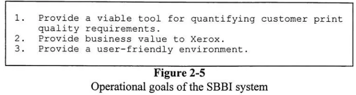
role.The
operational goals ofthe
SBBI
system are shownin Figure
2-5. The
first
goalreflects
the
impetus for
the
entire project.The
system wasdesigned
to
fill
abusiness
need;
andif it
cannotfill
that need, then
it is
afailure.
The
second goal statesthat
if
the
new system
is
nofaster
or cheaperthan the
oldsystem, then
it has
no valueto the
corporation.
The
third
goal reflectsthe
fact
that this
systemis
intended for
useby
individuals
whomay
notbe fluent in
UNIX
orC;
andif
they
can't understandit,
then
it is
useless
to them
as atool.
Chapter
4
will returnto these
pointsto
examinehow
wellthe
1. Provide a viable tool for quantifying customer print quality requirements.
2. Provide business value to Xerox. 3. Provide a user-friendly environment.
Figure
2-5
Operational
goals ofthe
SBBI
systemThe SBBI
systemis
atrue
client/server programfeaturing
a small server and afull-feature,
self-configuring
client.This
section provides an overview ofthe
key
operational and architectural
features
ofthe
system.The
most prominent operational and architecturalfeature
ofthe
SBBI
systemis
the
client/server structure ofthe
program.This
was adesirable feature because
ofthe
processing
requirements ofimage
processing.The
images
whichthe
SBBI
systemmanipulates are
large,
oftenexceeding
100
MB
in
size.Each
suchimage has
millions ofpixels,
and each pixelmay
consumemany
bytes
ofstorage,
depending
onthe
colordepth
ofthe
image.
The
effectiveprocessing
of suchimages
requires a computer with ahigh
speedCPU
andmany
megabytes ofmemory
anddisk
space.While
such computers exist withinXerox, they
are not common.The
client/server architecture ofthe
SBBI
system allowsthe
server,
whichhandles
allthe
image
processing,
to
reside on a remote computer.In
practice, this
remote computeris
usually
ahigh-power
workstation well equippedfor image
processing.The
client,
which provides allthe
userinteraction,
resides onthe
user's workstation.This
reducesthe
computational requirements ofthe
overall system and makes
it
availableto
a widerbase
of users.The
use of a client/server architectureis
not without complications.The SBBI
system requires
that the
serverbe
ableto
accessinput
images.
If
the
serveris
running
on a remotecomputer, these
images
may
notbe
accessibleto
it.
In
orderto
operatetransparently,
the
client computer and server computermust sharethe
directories
wherethe
images
are read andwritten.This
meansthat
one orboth
computers must accessthe
directory
over a network such asNFS
(the
Network
File
System)
orAFS
(the
Andrew
File System).
As
a practicalexample,
supposethe
input file is located
in
the
directory
/tmp
onthe
clientcomputer,
whichis
alocal
directory
notimported
or exported overthe
network.
When
the
server attemptsto
readthe
file,
it
will attemptto
locate it
in
/tmp
onthe
server's computer.This
would causethe
serverto
generate an error message.The
correctway
to
usethe
SBBI
systemis
to
locate
the
files in
acommon,
shareddirectory.
Many
sites,
including
Xerox
andRIT,
NFS
mount user'shome directories
to
a collection ofworkstations,
sothat
users canlog
in from
any
workstation and accessthe
samefiles.
Such directories
are acceptablelocations
for
input
and outputfiles,
sinceboth
the
clientandservermachine canaccess
the
samefiles
withthe
same path names. [image:18.574.120.486.87.185.2]The
server uses standardUNIX
socketsto
communicatesimultaneously
with oneor more clients.
The
serverhas
been
designed
to
perform all ofthe
worknecessary
to
makethe
client connection seamless.To
the user, the
serverappearsto
be
running
onhis
orher local
computer,
althoughin
reality
it
may
be
running
on a computer miles away.The
serveris designed
to
detect
and catch errors(including
those
generatedby
UNIX
when
the
shell scriptexecutes)
and pass appropriateinformation
back
to the
clientfor
processing.The
server alsoautomatically
changedirectories
and userids
to
matchthose
ofthe
client,
so permissions and relative path names work asthe
userexpects.The
operational metaphorthat the
client providesis both
simple andintuitive. At
its
coreis
the
concept of artifacts andboxes.
The
user viewsthe
artifactsasbeing
located
in
one oftwo
boxes:
abox
that
contains allthe
available artifacts and abox
that
containsthe
artifactsthat the
user wantsto
apply
to the
input
image.
Conceptually,
the
box
containing
allthe
available artifactshas
aninfinite
number of each artifact.The
goal ofthe
useris
to
move artifactsfrom
the
box
with allthe
available artifacts(the
available [image:19.574.77.511.324.644.2]artifacts
box)
andinto
the
box
of artifactsto
be
applied(the
applied artifactsbox).
To
help
the
userdo
this,
the
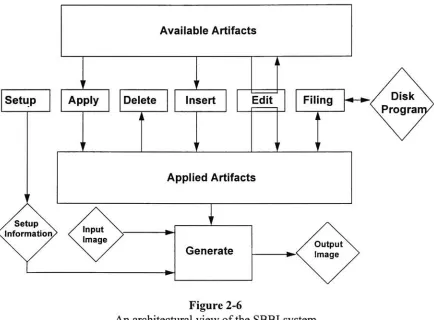
system provides a small set of simple operationsfor
moving,
deleting,
andrearranging
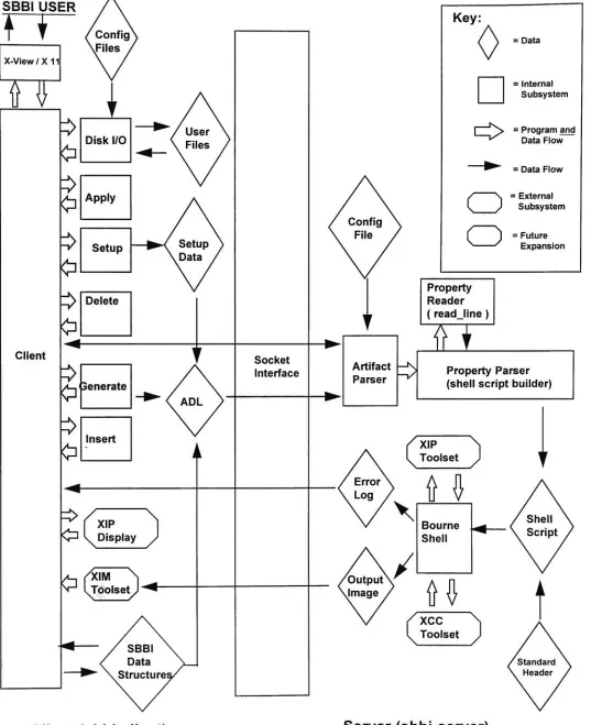
artifacts(see Figure 2-6).
Figure 2-6
An
architectural view ofthe
SBBI
systemArtifacts
areonly
allowedto
flow
from
the
available artifactsbox into
the
appliedartifacts
box into
the
available artifactsbox.
Because
the
available artifactsbox
canbe
viewed asholding
aninfinite
number of eachtype
ofartifact, there
is
no needto
move artifactsback into it.
Similarly,
when artifacts aredeleted
from
the
applied artifactsbox,
they
do
not needto
be
saved,
sothey
canbe discarded.
The
process ofmoving
an artifactfrom
the
available artifactsbox into
the
applied artifactsbox is
calledapply,
because
it
causesthat
artifactto
be
appliedto the
outputimage.
The only
time
an artifactleaves
onebox
and returnsto the
samebox is
during
an edit operation.This
allowsthe
userto
notonly modify
the
values of propertiesin
the
applied artifacts
box,
but
to
set newdefault
valuesfor
propertiesin
the
available artifactsbox.
Thus,
oncethe
userhas
markedthe
value of aproperty
as somevalue,
say
10.0,
it
will remain
10.0
each andevery
time that
artifactis
selected untilthe
nexttime
it is
changed.
The
edit operationis invoked
implicitly
whenthe
user selects an artifactfrom
eitherbox.
The
systemdoes
not provide a meansto
restorethe
originaldefault
value ofthe
property automatically
onceit has been
changed.A delete
operationis
providedto
allowthe
userto
remove an artifactpreviously
applied
to the
image.
This
causesthe
artifactto
be
removedfrom
the
applied artifactsbox
anddiscarded.
The
system provides no means ofundeleting
anartifact,
orfor
deleting
an artifactin
the
available artifactsbox (short
ofediting
the
configurationfiles,
seeAppendix
A).
A delete
all operationis
providedfor
removing
allthe
applied artifacts with one operation.An insert
operation existsfor
placing
an artifactinto
the
middle ofthe
appliedartifacts
list.
This
is
animportant feature because
the
orderof application of artifacts canbe
significant.In
this sense, the
applied artifacts canbe
thought
of as a program whoseprocessing
is directed
by
the
selection of artifacts.Taken
together,
the apply,
insert,
anddelete
operators allowthe
userto
controlnotonly
which artifactsareapplied,
but
alsothe
order
in
whichthey
are applied.The
filing
operation canbe
usedto take
allthe
artifactsin
the
applied artifactsbox
and place
them
into
adisk file.
These
disk files
canthen
be
readback
in
at alater date.
In
effect, this
allowsthe
userto
save astate of applied artifacts and retrievethis
state atwill.
As Figure 2-6
illustrates,
the
filing, insert,
anddelete
options canonly
be
usedto
modify,
save,
and restorethe
contents ofthe
applied artifactsbox,
notthe
availableartifacts
box.
The setup
operation allowsthe
userto
specify
the
names ofthe
input
and outputfiles,
as wellas whatform
the
outputfile
shouldtake
(on-screen
preview orPostScript).
From here
the
user can alsospecify
if
the
outputfile
shouldbe
compressed,
andthe
scaling factor
to
apply
to the
image
whenthe
output modeis
preview(this
allowsthe
userto
scalethe
image
sothat
the
processing
willtake
less
time
and sothe
image
willfit
onTo
producethe
outputimage,
the
user utilizesthe
generate operation.This
causes
the
systemto
readthe
input
image,
apply
the
artifacts,
and generate an outputimage.
This
outputimage
canbe displayed
on screen or sentto
aPostScript
printer.The
setup
option allowsthe
userto
specify
the
format
ofthe
outputfile.
The SBBI
systemhas
the
ability
to
generate multiple prints with a single run.This
batch
mode of operationis
animportant
convenience whengenerating
a series ofprints.
The SBBI
system allowsthe
userto
setthe
"value" ofone or more(numeric)
properties not
to
a singlevalue,
but
to
a range of values.To
usethis
feature,
the
usermust enter
three
pieces ofinformation:
the
startvalue, the
stop
value,
andthe
number ofprints.
The
system willthen
generate a series ofprints,
incrementing
ordecrementing
the
properties as neededfor
each print.For
example, the
usercanspecify
that
someproperty,
callit
amplitude,
shouldhave
a start value of1
and afinal
value of5.
The
userthen tells
the
system(in
the
setup
box)
to
generatethree
prints.This
will causethree
printsto
be
generated,
the
first
with an amplitude of1,
the
next with an amplitude of3,
andthe
final
with an amplitude of
5.
If
morethan
oneproperty
is
configuredin
this
mannerthen
allthe
properties willbe
updated with eachiteration
ofthe
loop.
The
system provides nomechanism
for
handling
the
nesting
ofthese
loops.
The SBBI
system providesthe
user notonly
with a predefined set ofartifacts,
but
mimmum/maximum and
default
valuesfor
eachproperty
associated withthat
artifact.This
type
ofdesign
relievesthe
user ofthe
burden
ofmemorizing
artifacts andproperties,
and prevents
him
orher
from
entering
invalid
valuesfor
properties.One
ofthe
most usefulfeatures
ofthe
SBBI
systemis
the
self-configurationthat
both
the
client and server undergo at runtime.
Under
most client/serverapplications,
fundamental
changesto the
system requirethe
editing
and recompilation ofboth
the
client and
the
server.Under
the
SBBI
system, the
most commontype
of changeis
the
inclusion
of a new artifact orproperty,
orthe
editing
of anexisting
artifact or property.To
simplify
this
task,
both
the
client and server readASCII
configurationfiles
that
allowthem to
build
aninternal database
of artifacts and properties.The
client'sdatabase
allowsthe
clientto
determine
the
name of eachartifact, along
withthe name,
type,
default
value,
minimum
value,
maximumvalue,
andhelp
information for
each property.The
server'sdatabase
allowsthe
serverto
constructthe
parser requiredto
build
shell scripts.Chapter
3 discusses
the technical
details
of self-configuration.Appendix A
discusses
how
to
modify
the
configurationfiles
to
alterthe
behavior
ofthe
system.The
SBBI
systemhas been designed
to
shieldthe
userfrom
the
needto
know how
the
imaging
is done (see
Chapter
3)
andthe
details
of each artifact.The
layout
ofthe
interface has been designed
to
reflectthe
operational metaphor(Figures
2-6
andA-l).
The
available artifacts arelisted in
the
left hand
box,
whilethe
artifacts arelisted in
the
right
hand box.
Artifacts conceptually
movefrom left
to
right.The buttons
whichfacilitate
this
movementlie in
the
middle ofthe
screen,
between
the two
boxes.
Each
operation
has
a separate and clearly-markedbutton
associated withit.
The
systeminstructions.
These
status messages aredesigned
to
orient and guidethe
userthrough the
operation of
the
program.Finally, help
information for
eachproperty
canbe
provided.Each
property
in
the
configurationfile has
an optional componentcontaining
the
pathname of an
ASCII
file containing
help
information for
that
property.When
the
userselects a
property
and clicks onthe
help
button,
the
system will startup
a simple texteditor
to
display
the
contents ofthe
corresponding
help
file
(if
it
exists).Figure
2-7
summarizesthe
key
operational and architecturalfeatures
ofthe
SBBI
system.
The
final
productbuilds
onthe
strengths ofthe
ink jet
printhead andfull-page
image
simulations,
whileadding
features
and capabilities neverimplemented in
either ofthese
systems.The
new additions makethe
SBBI
system notjust
a valuable researchtool,
but
a viableengineering
andbusiness
one as well.Feature
Client
/ Server
ArchitectureUNIX
Socket IPCError
Handling
Simple,
consistent metaphorFiling
Automatic generation of multiple
prints,withvarying propertyvalues
Default values, rangechecking, and
help
information for
propertiesSelf-configuration
Help
informationBenefit Analysis
Reduces computingresource requirements.
Portabletowiderange of platforms.
Catches user and programming mistakes. Displays meaningful errormessages,even
if
theerror originated on theserver side.Easy
toleam,
easytomaintain.Appliedartifacts
(state)
canbe
stored and retrievedUser can generate a controlled series of prints in one operation.
No memorization ofproperty names,
types,
permissiblevalues,or meanings required.
Newartifacts can
be
added more easily.Nomemorizationof crypticpropertymeanings
Figure
2-7
Architectural
andOperational Features
ofthe
SBBI
systemChapter 3
The Design
and
Implementation
of
the
SBBI System
Xerox
has invested
a significant amount oftime
andmoney providing
hardware
and softwaretools
for image
processing.These
tools
are well-designed andwell-tested,
but
not alwaysuser-friendly
in
practice.The
use ofthese
tools
in
research effortslike
the
full-page
image
simulation project requiredthe
userto
create and maintain complex shellscripts
by
hand. The
user wasoften requiredto
memorize cryptic argumentsto
XIP
andXCC
programs.From
the
development
standpoint,
it
wasdesirable
to
leverage
the
strengths of
these tools
whileadding
newfeatures
to
makethe
system moreuser-friendly
and easierto
extend.Four
key
design
goalsfor
the
SBBI
system wereidentified
early
in
the
development
effort(see Figure 3-1).
These
goals constitutedthe
foundation for
the
development
ofthe
SBBI
system.1.
Leverage
existing
hardware
and software2. Integrate
existing
toolswith each other andtherestofthesystem.3. Permit
theeasyinclusion
of newartifactsand properties.4.
Provideauser-friendlyenvironment.Figure
3-1
Design
goals ofthe
SBBI
system3.1
Assumptions
The SBBI
systemhas been designed
to
be
adaptableto
changing
business
needs.It
wasnecessary,
however,
to
identify
those
assumptionsthat
were requiredin
orderto
fix
the
initial design
and worktoward
some recognizablefinal
configuration.Otherwise,
the
development
ofthe
system couldbecome
an open-endedeffort,
with no constraintsregarding
wherethe
effortshouldbegin
or end.3.1.1
Build for
the trained
userThe
usershould understandthe
basic
principles of modern printmarking
engines.In
particular, the
user must understandthe
nature ofthe
artifactsthat
the
program uses.This
is
requiredto
explore withthe
customer(who
in
alllikelihood is
notthe
user)
eachof
the types
ofartifacts,
what causesthe artifacts,
andthe
consequences ofremoving
orreducing
the
artifacts.For
example, the
user shouldbe
ableto
explainto
the
customer [image:23.574.107.469.302.452.2]causing
somebands
oftoner
orink
to
fall
too
closeto the
adjoining
bands,
and othersto
fall
too
far
apart.This
effect canbe
minimized with certaintypes
ofdesigns,
but
the consequencemay be
ahigher
cost and/or an unacceptableincrease in
one ofthe
otherartifacts.
The
user mustbe
ableto
explainthese
considerationsto the
customer todetermine
the
acceptabletolerances
of all appropriate artifacts.3.1.2 Leverage existing
componentsThe
system should utilizeexisting
Xerox
imaging
tools.
These
tools
are welldocumented
andhighly
optimizedfor
this type
ofimaging.
In
particular,
it
shouldleverage
the
Xerox
Image
Processing
toolset
andthe
Xerox Color
Correction
toolset
These
programs areideal because
most ofthe
required routines arealready
presentin
a stable and optimized environment.In
addition, these tools
have been designed
to
accommodate
the
inclusion
of newroutines,
such as mightbe
requiredto
implement
additional
SBBI
visual artifacts.3.1.3
Standard
platformThe
system should runonSun
workstationsrunning MIT's X Window
Systemversion
11
andSun's Open
Windows window manager.This
platform was chosenbecause
Sun
workstations arereadily
available withinXerox
andthe
X Window System
is
portableto
a wide range of alternate platforms.In
addition,
many
ofthe tools
usedby
the
SBBI
system run underX
Windows
andOpen
Windows,
including
the text
editor usedfor
displaying
runlogs
andthe
XIP
display
program usedto
handle
on-screen previews.3.1.4 Standard Language
It
is
assumedthat this
product willbe in
usefor
sometime.
The
decision
wasmade,
therefore,
to
do
the
development
in
the
C programming language (ANSI C).
While
C
is
notthe
most expressivelanguage
for
this type
ofapplication,
it does have
the
advantage of
being
widely
used and supportedwithinXerox.
In
addition,
C
is
the
mostnatural
language
to
usefor
the
development
ofUNIX
andX
Windows
applications(because
the
UNIX
andX Window System libraries
arethemselves
writtenin C).
3.1.5 External Printer Service Vendors
The SBBI
system produces outputboth
on-screen andin PostScript files.
These
files
canbe
printed onany PostScript
device,
or convertedinto
other pagedescription
languages using
appropriatetools.
At
times,
usersmay
wishto
sendthese
files
to
externalvendorsfor
lithographic (or other)
printing.These
vendors must understandthat
the
presence of visualdeformations
is
intentional
and must not undertaketo
remove orminimize
them.
To
do
sowould underminethe
intent
ofthe
entire process.3.2
A
Brief Tour
ofthe
Development
Process
Because
this
was a research projectin
the truest sense,
it
was not clear atthe
beginning
whatthe
optimaldesign
wouldbe.
Accordingly,
a rapidprototyping
development
style was adopted.Within
afew
days
ofinitiating
the
project a prototypewas
developed
that
implemented
the
basic features
ofthe
SBBI
system.Over
the
course ofthe
nextfew
monthsthis
version was modified andfleshed
outto
determine
the
optimal configuration of
the
final
system.3.2.1
Understanding
the
SBBI
data
structuresSimulations
aredesigned
to
mimicthe
appearance and actions of real systems.To
do
so, the
simulation mustdescribe
the
systemcompletely
anddrive
the
system properly.In programming
terms,
the
description
ofthe
systemis facilitated
by
the
proper choice ofdata
structures,
whilethe
operation ofthe
systemis facilitated
by
the
proper program structure and organization.The
design
of expressivedata
structures,
and convenientroutines
to
manipulatethem,
is
a criticalfirst
step
in
any
simulationprogram6.As
the
exact number andtype
of artifactsin
the
final
systemis
notfixed,
the
SBBI
system needed a
flexible
and powerfulway
to
manipulatethese
entities.At
its
mostbasic
level,
the
system maintains an unknown number ofartifacts,
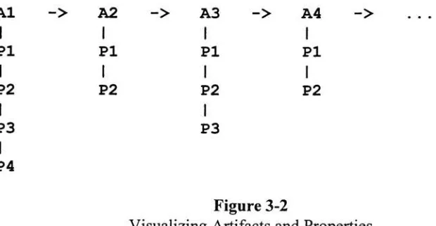
each with an unknown number of properties.A
system of singlelinked lists
was usedto
describe
and managethis
structure,
with each artifactbeing
tied to the
artifact nextto
it in
the chain,
and each artifacthaving
anindependent
chain of properties associated withit.
Figure 3-2
pictorially
illustrates
this relationship,
withAs representing
artifacts andPs
representing
properties.Al
->A2
->A3
->A4
->PI
IPI
iPI
iPI
IP2
i1
P2
1
P2
i1
P2
1
P3
i1
P3
1
P4Figure
3-2
Visualizing
Artifacts
anc1
Properties
In
the
first
version ofthe program,
a set oftypes
and routines were adoptedto
create, manage, edit,
anddelete
this
data
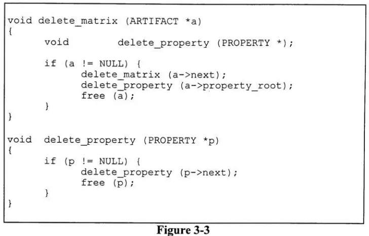
structure.Because
this
data
structure containssingle
linked
lists,
the
structurelends
itself
wellto techniques
such as recursivetraversal.
Figure 3-3 illustrates how
this
particulardata
structure canbe
easily
managedusing
[image:25.574.108.418.443.604.2]delete
the
entirelist in
onefunction
call.Routines
were alsodeveloped
to
look
up
eachartifact and
property
by
name and position and return pointersto the
appropriateentity
withinthe table.
void delete_matrix (ARTIFACT
*a)
{
void
delete_property
(PROPERTY*);
if (a !=
NULL)
{
delete_matrix
(a->next)
;delete_property
(a->property_root)
; free(a)
;}
void
delete_property
(PROPERTY*p)
{
}
if
(p
!=NULL)
{
delete_property
(p->next)
; free(p)
; [image:26.574.120.484.122.355.2]}
Figure 3-3
C
codefragment
illustrating
the
manipulation ofthe
SBBI data
structure.3.2.2
SBBI
client/serverdesign
Manipulating
large images
requires a greatdeal
ofmemory
andprocessing
power.Many
"of
the
images
that the
SBBI
systemhandles
arehundreds
of megabytesin
size.The
introduction
of artifactsto the
image
may
requirefairly
intense
computations at eachand
every
pixel.The
problemis
compoundedif
the
introduction
ofthe
artifact requiresfloating
point mathematics.Add
to this the
potentialfor
generating
several prints at atime
andit's
possibleto
estimatethat
executiontimes
will runinto days
or even weeks.One
way
to
addressthis
problemis
to
runthe
image
processing
on ahigh-speed
processor.
However,
not everyone atXerox
has (or
canafford)
that
kind
of computer.The
client/server architecture ofthe
SBBI
system alleviatesthis
problemby
allowing
the
client
(which
provides allthe
userinteraction)
to
run on one machine whilethe
server(which
does
allthe
image
processing)
runs