UNIVERSITI TEKNIKAL MALAYSIA MELAKA
THE OPTIMIZATION OF WELDING PARAMETER FOR
JOINING MILD STEEL 1020 USING ABB METAL INERT GAS
(MIG) ROBOT WELDING
This report submitted in accordance with requirement of the Universiti Teknikal Malaysia Melaka (UTeM) for the Bachelor Degree of Engineering Technology
(Process and Technology) (Hons.)
by
NUR FATIHAH BINTI NASRUDIN B071410549
951117105118
UNIVERSITI TEKNIKAL MALAYSIA MELAKA
BORANG PENGESAHAN STATUS LAPORAN PROJEK SARJANA MUDA
TAJUK: The Optimization of Welding Parameter for Joining Mild Steel 1020 Using ABB
Metal Inert Gas (MIG) Robot Welding
SESI PENGAJIAN: 2017/2018 Semester 1
Saya NUR FATIHAH BINTI NASRUDIN
mengaku membenarkan Laporan PSM ini disimpan di Perpustakaan Universiti Teknikal
Malaysia Melaka (UTeM) dengan syarat-syarat kegunaan seperti berikut:
1. Laporan PSM adalah hak milik Universiti Teknikal Malaysia Melaka dan penulis. 2. Perpustakaan Universiti Teknikal Malaysia Melaka dibenarkan membuat salinan untuk
tujuan pengajian sahaja dengan izin penulis.
3. Perpustakaan dibenarkan membuat salinan laporan PSM ini sebagai bahan pertukaran antara institusi pengajian tinggi.
4. **Sila tandakan ( )
SULIT
TERHAD
TIDAK TERHAD
(Mengandungi maklumat yang berdarjah keselamatan atau
kepentingan Malaysia sebagaimana yang termaktub dalam
AKTA RAHSIA RASMI 1972)
(Mengandungi maklumat TERHAD yang telah ditentukan oleh
organisasi/badan di mana penyelidikan dijalankan)
NUR FATIHAH BINTI NASRUDIN
No. 3, Jalan P8E/5, Presint 8,
Putrajaya
62250, W.P. Putrajaya
Tarikh: 10 JANUARI 2018
Tarikh: ________________________
Disahkan oleh:
MOHD HAIRIZAL BIN OSMAN
Cop Rasmi:
Tarikh: _______________________
i
DECLARATION
I hereby, declared this report entitled “The Optimization of Welding Parameter For Joining Mild Steel 1020 Using ABB Metal Inert Gas (MIG) Robot” is the results of my
own research except as cited in references.
Signature : ……….
Author’s Name : NUR FATIHAH BINTI NASRUDIN
ii
APPROVAL
This report is submitted to the Faculty of Engineering Technology of UTeM as a partial fulfillment of the requirements for the degree of Bachelor of Engineering Technology (Process and Technology) with Honours. The member of the supervisory is as follow:
……….
iii
ABSTRAK
iv
ABSTRACT
v
DEDICATIONS
vi
ACKNOWLEDGEMENT
In the name of Allah S.W.T, The Most Beneficial and The Most Merciful. It is with deepest serve gratitude of the Al-Mighty that gives me strength and ability to complete this final year project report.
First of all, I would like to take this opportunity to express my special thanks to my supervisor, Mr. Mohd Hairizal Bin Osman for the guidance, assistance, advise, kindness and also being helpful to guide me all the way through the development and progress of my final year project. Above all and the most needed, he provided me unflinching encouragement and support in various ways.
My appreciation also goes to my friends for their advice, supervision, and crucial contribution, which made them a backbone of this project to become successfully. Thank you for lending hands during progress of the project.
vii
TABLE OF CONTENT
ABSTRAK III
ABSTRACT IV
DEDICATIONS IV
ACKNOWLEDGEMENT VI
TABLE OF CONTENT VII
LIST OF TABLE XI
LIST OF FIGURES XII
LIST OF ABBREVIATIONS, SYMBOLS AND NOMENCLATURE XVI
CHAPTER 1 : INTRODUCTION 1
1.0 Introduction 1
1.1 Background of study 1
1.2 Problem Statement 2
1.3 Objective 3
1.4 Scopes 3
CHAPTER 2: LITERATURE REVIEW 5
2.0 Introduction 5
2.1 Joining Technology 5
2.1.1 Welding 6
2.1.2 Brazing 6
2.1.2.1 Torch Brazing 7
2.1.2.2 Furnace Brazing 8
2.1.2.3 Silver Brazing 10
2.1.2.4 Dip Brazing 11
2.1.3 Soldering 12
viii 2.1.4 Adhesive Bonding 15
2.1.5 Mechanical Fastening 16
2.2 Introduction to Welding 17
2.2.1 Geometry of Welding 18
2.2.2 Quality of Welding 19
2.2.3 Heat Affected Zone 20
2.2.4 Safety issues 20
2.3 Types of welding 20
2.3.1 Shielded-Metal Arc (SMAW) or Stick Welding 21
2.3.2 Gas-Metal Arc Welding (GMAW) 21
2.3.3 Friction Welding 23
2.3.4 Spot Welding 23
2.4 Welding Parameter for MIG Welding 24
2.4.1 Current 25
2.4.2 Voltage 25
2.5 Carbon Steel 28
2.5.1 Low Carbon Steel 28
2.5.2 Medium Carbon Steel 28
2.5.3 High Carbon Steel 29
2.5.4 Very High Carbon Steel 29
2.7 Applications of Low Carbon Steel 1020 30
2.8 Minitab Software 30
2.9 Taguchi Method 32
2.10 Analysis of Variance (ANOVA) 43
2.10.1 Statistic Test for ANOVA 50
2.11 Tensile Strength 53
CHAPTER 3: METHODOLOGY 55
3.0 Introduction 55
3.1 Methodology 55
ix
3.3 Preparation for Experiment 58
3.3.1. Material 58
3.3.2 MIG Robot Welding 59
3.4 Preparation process 60
3.4.1 Mild Steel Plate Preparation 60
3.5 Welding Parameter Setup 62
3.5.1 Parameter Setting 62
3.5.2 Taguchi Method 63
3.6 Welding process 67
3.6 Cut into ‘dogbone’ Process 69
3.7 Tensile Testing Process 70
3.8 Analyze Data 73
CHAPTER 4: RESULT AND ANALYSIS 76
4.0 Introduction 76
4.1 Result of the Experiment 76
4.1.1 Graph Obtained from Tensile Test 78
4.1.1 The Average Tensile Strength 87
4.1.2 Results of Signal to Ratio and Mean 91
4.1.3 Main effects plot for S/N Ratio and Means 91
4.1.4 Response Table for S/N Ratio and Mean 94
4.2 Taguchi Analysis Prediction 97
4.3 Confirmation Test 98
4.4 Analysis of Variances (ANOVA) 99
CHAPTER5: CONCLUSIONS 102
5.0 Introduction 102
5.1 Summary of Research 102
5.2 Achievement of Research Objectives 103
x
REFERENCES 104
xi
LIST OF TABLE
1.1 Type of parameter 2
1.2 Experimental layout using Taguchi Method 3
2.1 Example of L9(32) Array 36
2.2 Example of L4(23) Array 37
2.3 Example of L9(44) Array 38
2.4 Example of L9(32) Array 38
2.5 Signal to Noise Ratio 40
2.6 Summary of ANOVA 50
3.1 Machining Parameter 62
3.2 The Parameter of three factor 63
3.3 The Experimental Design using 𝐿9 Orthogonal Array 65
3.4 Welding Parameter using Taguchi Method 66
4.1 Level of Parameter and Observed Value 77
4.2 Experimental Layout using Taguchi Method 77
4.3 The Taken Value Tensile Test for Every Specimen 87 4.4 The Value of Average Tensile Test for Each Specimen 88
4.5 The Result for Means and S/N Ratio 91
4.6 Response Table for S/N Ratio 94
4.7 Response Table for Means 95
4.8 The result for optimum parameter 98
xii
LIST OF FIGURES
2.1 The Brazing Schematic 7
2.2 Process of Torch Brazing 8
2.3 Furnace Brazing Schematic 9
2.4 Furnace Brazing Process 9
2.5 Silver Brazing using Silver Alloys 10
2.6 Dip Brazing Schematic 11
2.7 Dip Brazing Process 11
2.8 The Soldering Process 12
2.9 Silver Soldering Process on Silver 13
2.10 The Induction Brazing Process 14
2.11 Structure of Adhesive Bonding 15
2.12 Types of Mechanical Fastening 16
2.13 Example of the Mechanical Fastening 17
2.14 Types of Welding Joint 18
2.15 An Illustration of Good Welding Quality 19
2.16 Shielded-Metal Arc 20
2.17 Gas-Metal Arc Welding (GMAW) 21
2.18 Friction Welding 23
2.19 Spot Welding 24
xiii 2.22 Image of Different Welding Quality using Different Welding Speed 27 2.23 Image of Different Welding Quality using Different Gas Flow Rate 27 2.24 Composition of steel and iron for each type of carbon steel 29
2.25 Logo of Minitab Software 31
2.26 Dr Genichi Taguchi 32
2.27 F- Distribution Graph 44
2.28 Example of ANOVA 45
3.1 Project Flow Chart 56
3.2 Process Flow Chart 57
3.3 Simulation Diagram of Robot Arc Welding using Metal Inert Gas 59
3.4 MIG Robot Welding 59
3.5 Mild Steel plate dimension 61
3.6 Mild Steel plate after grooving process 61
3.7 The selection in Minitab for Taguchi Method 63
3.8 The Assign Factor and Level 64
3.9 Orthoganal Array Design 64
3.10 Taguchi Method Arrangement using Minitab 66
3.11 The Position of the Plate for Welding Operation 67
3.12 The Plate after Welding Process 67
3.13 Welding Process 68
3.14 Flow Chart for Welding Process 68
3.15 The Dimensions of the Part for Testing Process 69
xiv
3.17 The Specimens after Cut 70
3.18 Tensile Test Machine INSTRON 600DX 71
3.19 The Tensile Testing Process 71
3.20 Example of the Graph Obtained From the Test 72
3.21 Flowchart for Tensile Test 72
3.22 The Specimen after Tensile Test 73
3.23 The Selection in Minitab for Anlyze Data 74
3.24 Selection for Signal to Noise Ratio 74
3.25 The Factor and Level Input to get the Predicted Value 75
xv 4.15 Result of the Third Specimen from Experiment 5 82 4.16 Result of the First Specimen from Experiment 6 83 4.17 Result of the Second Specimen from Experiment 6 83 4.18 Result of the Third Specimen from Experiment 6 83 4.19 Result of the First Speciment from Experiment 7 84 4.20 Result of the Second Specimen from Experiment 7 84 4.21 Result of the Third Specimen from Experiment 7 84 4.22 Result of the First Specimen from Experiment 8 85 4.23 Result of the Second Specimen from Experiment 8 85 4.24 Result of the Third Specimen from Experiment 8 85 4.25 Result of the First Specimen from Experiment 9 86 4.26 Result of the Second Specimen from Experiment 9 86 4.27 Result of the Third Specimen from Experiment 9 86
4.28 Main Effects Plots for S/N ratios 93
4.29 Main Effects Plots for Means 93
4.30 The prediction value for optimum parameter 97
xvi
LIST OF ABBREVIATIONS, SYMBOLS AND
NOMENCLATURE
ANOVA - Analysis of Variance
Al - Aluminium
MIG - Metal Inert Gas
GMAW - Gas Metal Arc Welding HAZ - Heat Affected Zone
SMAW - Shielded-Metal Arc Welding OA - Orthogonal Arrays
DoE - Design of experiment S/N - Signal-to-Noise ratios
AISI - America Iron and Steel Institute
ASTM - American Standard Testing and Material UTS - Ultimate Tensile Strength
1
CHAPTER 1
INTRODUCTION
1.0 Introduction
This chapter includes the background of the study, problem statement, objective and scope. This chapter is an initiation to the whole project about joining low carbon steel 1020 using Metal statement, objectives that is expected to be achieved and the scope of the study that is going to be conducted.
1.1 Background of study
2 system. MIG welding provides a faster process than other forms of welding, especially when robots are incorporated. The first robot welding machine established is when the automotive industry began using robots extensively for spot welding. This welding machine was used widely because it gave better result than manpower itself. The accuracy and precision of robot welding give the best output. MIG welding robots are capable in all position, this factor helps the welding system to be more flexible, higher quality welds can be and more efficient processes are just some of the advantages of MIG welding automation. The factor of safety for the welder is also increases as it is safe from dangerous fumes, higher quality welds can be improved and the efficiency of the welding process can be enhanced. Tensile test is also known as tension test is probably the most fundamental type of mechanical test that can be performing on welding part to see the strength of welding area. Tensile tests are simple, relatively inexpensive, and fully standardized. By pulling on something, you will very quickly determine how the material will react to forces being applied in tension.
1.2 Problem Statement
3
1.3 Objective
The objective of this project includes the main point of the research and the result that we can get from the research. These are the following objectives:
I. Examine the strength of the welding area for the different specimen using different parameter.
II. To examine the factor that gives more contribution on welding strength
III. To determine the optimum welding parameter for joining Mild Steel plate 1020.
1.4 Scopes
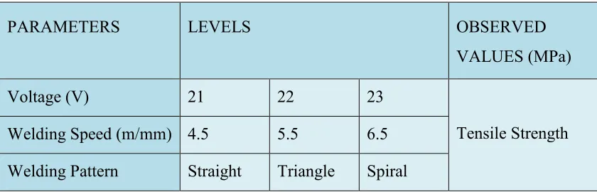
[image:21.612.117.537.533.668.2]Firstly, cut the raw material to the needed dimensions is 140mm (length) x 130mm (width) x 6mm (thickness). On every pair of plate, there will be a groove (30˚). The welding parameter will be setup on the machine, there will be nine samples with different parameter. The welding process is fully conducted using MIG robot welding. After the welding process, each of the samples will go through the tensile test. The result for each plate with different parameter will be examined.
Table 1.1: Type of parameter
PARAMETERS LEVELS OBSERVED
VALUES (MPa)
Voltage (V) 21 22 23
Tensile Strength Welding Speed (m/mm) 4.5 5.5 6.5
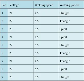
4 Table 1.2: Experimental layout using Taguchi Method
Part Voltage Welding speed Welding pattern
1 21 4.5 Straight
2 22 5.5 Triangle
3 23 6.5 Spiral
4 21 4.5 Spiral
5 22 5.5 Straight
6 23 6.5 Triangle
7 21 4.5 Triangle
8 22 5.5 Spiral
5
CHAPTER 2
LITERATURE REVIEW
2.0 Introduction
In this chapter, it consists of literature review by the previous researched based on articles, books, journal and other sources. The explanation of this chapter included about the Metal Inert Gas (MIG) Welding, welding parameter, and material of mild steel and design of the experiment. It covers all the information that has been used in this research and project.
2.1 Joining Technology
6
2.1.1 Welding
Welding process usually takes place in joining metal because it required a high temperature during the process. Two or more parts are joined permanently at their touching surfaces by a suitable application of heat. Usually used a filler material as a molten material to form a joint between the parts.
2.1.2 Brazing
Brazing is different from welding because it does not melt the base metal. Brazing process takes place by melting the filler and flowing through the gap of the part. The filler metal flows into the gap between close-fitting parts by capillary action. The filler metal is brought slightly above its melting temperature while protected by a suitable atmosphere, usually a flux. It then flows over the base metal and is then cooled to join the work pieces together (Groover, Mikell P., 2007).
In a journal from 1989, Scwartz state that high quality brazed joints requires that parts be closely fitted, and the base metals exceptionally clean and free of oxides. Cleanliness of the brazing surfaces is also important, as any contamination can cause poor wetting flow. The two main methods for cleaning parts, prior to brazing, are chemical cleaning and abrasive or mechanical cleaning. Other than that, the other consideration that has to take control while brazing is the effect of temperature and time on the quality of brazed joints. When the temperature of the braze alloy increasing, the alloying and wetting action of the filler metal increases as well.