University of Southern Queensland Faculty of Engineering and Surveying
EFFECTIVENESS OF LIME STABILISATION
ON REACTIVE SOILS FOR MAIN ROADS
A dissertation submitted by Paul Lindsay Wilson
In fulfilment of the requirements of
Courses ENG4111 and ENG4113 Research Project
towards the degree of Bachelor of Engineering (Civil)
Effectiveness Of Lime Stabilisation On Reactive Soils For Main Roads Page i
ABSTRACT
The Department of Transport and Main Roads (DTMR) manages the state controlled road system in Queensland comprising the major traffic carrying and strategic roads in the state. A vast majority of these state controlled roads are located in areas where the insitu material is dominated by reactive soil. Mixing lime with the reactive subgrade is a stabilisation technology to not only improve construction workability in these soils but to also reduce maintenance frequency on the road system.
Lime stabilisation is used to modify sub grade soils to improve constructability by improving plastic properties, flocculating particles and drying the material. Studies indicate that lime stabilisation will improve load bearing capacity and will also achieve long term strength retention.
DTMR Specifications and AUSTROADS Pavement design guidelines for lime modified sub grade recommends the Unconfined Compressive Strength achieve a minimum of 1.5MPa at 28 days (unsoaked). This research will assess current test results against the original test results at completion of construction.
DTMR standards specify that lime stabilisation of subgrade material shall be carried out as 2 passes by applying half the dose in the first pass, waiting 24 hours then applying the remaining dosage in the last pass. This time period between passes is called the Amelioration Period.
The major issue with having a 24 hour period for amelioration is it takes a longer time to finish construction. This delay has potential impacts on the contractor and exposes the open subgrade to potential weather such as rain for a longer period.
Amelioration is necessary in heavy clays as adequate mixing is difficult to achieve in one pass as heavy clays tend to clump together. Allowing 24 hours between passes permits the lime to flocculate clay particles and improve workability. Amelioration results in better mixing in the second run and construction also becomes easier. This research will test a range of reduced time period to determine what length of time will achieve the Unconfined Compressive Strength of 1.5MPa.
Effectiveness Of Lime Stabilisation On Reactive Soils For Main Roads Page ii
University of Southern Queensland
Faculty of Engineering and Surveying
ENG4111 Research Project Part 1 &
ENG4112 Research Project Part 2
LIMITATIONS OF USE
The Council of the University of Southern Queensland, its Faculty of Engineering and Surveying, and the staff of the University of Southern Queensland, do not accept any responsibility for the truth, accuracy or completeness of material contained within or associated with this dissertation.
Persons using all or any part of this material do so at their own risk, and not at the risk of the Council of the University of Southern Queensland, its Faculty of Engineering and Surveying or the staff of the University of Southern Queensland.
This dissertation reports an educational exercise and has no purpose or validity beyond this exercise. The sole purpose of the course pair entitled “Research Project” is to contribute to the overall education within the student's chosen degree program. This document, the associated hardware, software, drawings, and other material set out in the associated appendices should not be used for any other purpose: if they are so used, it is entirely at the risk of the user.
Professor Frank Bullen
Dean
Effectiveness Of Lime Stabilisation On Reactive Soils For Main Roads Page iii
CERTIFICATION
I certify that the ideas, designs and experimental work, results, analyses and conclusions set out in this dissertation are entirely my own effort, except where otherwise indicated and acknowledged.
I further certify that the work is original and has not been previously submitted for assessment in any other course or institution, except where specifically stated.
Paul Lindsay Wilson
Student Number: 0018060035
_______________________________ Signature 25 October 2011
Effectiveness Of Lime Stabilisation On Reactive Soils For Main Roads Page iv
ACKNOWLEDGEMENTS
I would like to acknowledge and thank the following people for their assistance and support throughout the duration of this project.
I would firstly like to thank my university supervisor, Dr Soma Kathirgamalingam for his patience, assistance and guidance through the course of this project and my industry supervisor Mr Jothi Ramanujam (DTMR) for challenging my concepts and supporting my experiments.
I would also like to thank Anthony Neary and staff of Department of Transport and Main Roads Pavements, Materials, Geotechnical & Standards Branch at Herston, Brisbane for geotechnical testing support.
Most importantly, I thank my wife Lisa and children Gabe and Cassidy for their support, love and encouragement in completing my university studies.
Paul Wilson
Effectiveness Of Lime Stabilisation On Reactive Soils For Main Roads Page v
TABLE OF CONTENTS
Abstract ... i
Limitations of Use ... ii
Certification... iii
Acknowledgements ... iv
Table of Contents ... v
List of Tables... viii
List of Figures ... ix
Glossary ... xi
1 INTRODUCTION ... 1
1.1 Introduction ... 1
1.2 The Problem ... 2
1.3 Research Aims ... 3
1.4 Research Approach ... 3
1.5 Dissertation Outline ... 4
2 LITERATURE REVIEW ... 5
2.1 Introduction ... 5
2.2 Properties of Lime ... 5
2.2.1 Quicklime ... 6
2.2.2 Hydrated Lime ... 6
2.3 Properties of Reactive Soils... 7
2.4 Chemistry of Lime Stabilisation ... 8
2.4.1 Soil Modification ... 8
2.4.2 Soil Stabilisation ... 9
2.4.3 Pozzolanic Reactions ... 10
2.5 Design ... 10
2.6 Properties and Characteristics of Lime Treated Soils ... 11
2.6.1 Compaction Characteristics ... 11
2.6.2 Plasticity and Workability ... 12
2.6.3 Swell Potential ... 14
2.6.4 Strength ... 14
2.6.5 Deleterious Materials ... 14
Effectiveness Of Lime Stabilisation On Reactive Soils For Main Roads Page vi
2.7 Stabilised Subgrade Construction ... 16
2.7.1 Department of Main Road Construction Procedures ... 16
2.8 Amelioration ... 20
2.9 Pavement Performance ... 22
2.9.1 Strength ... 22
2.9.2 Resilient Modulus / Stiffness ... 22
2.9.3 Fracture and Fatigue ... 22
2.9.4 Durability ... 22
2.10 Lime Stabilisation in Queensland ... 22
2.11 Chapter Summary ... 25
3 LIME STABILISED SUBGRADE STRENGTH ... 26
3.1 Background ... 26
3.2 Design of Lime Content ... 26
3.3 Subgrade Strength at Construction ... 28
3.4 Present Subgrade Strength ... 30
3.4.1 Methodology ... 30
3.4.2 Laboratory Testing ... 31
3.4.3 Results ... 32
3.4.4 Long Term Unconfined Compressive Strength ... 34
3.4.5 Capillary Rise ... 35
3.5 Discussion ... 37
3.6 Chapter Summary ... 38
4 AMELIORATION PERIOD ... 39
4.1 Background ... 39
4.2 Amelioration Issues ... 39
4.3 Methodology ... 40
4.3.1 Classification Testing ... 40
4.4 Results ... 49
4.4.1 Classification Testing ... 49
4.4.2 Unconfined Compressive Strength Results ... 53
4.5 Discussion ... 56
Effectiveness Of Lime Stabilisation On Reactive Soils For Main Roads Page vii
5 CONCLUSION AND FURTHER WORKS ... 59
5.1 Achievement of Project Aims ... 59
5.2 Conclusion ... 59
5.3 Further Work ... 61
LIST OF REFERENCES ... 62
APPENDICES ... 64
Appendix A Project Specification ... 65
Appendix B UCS Test Record ... 66
Appendix C Test Results for Emerald Soil ... 67
Appendix D Test Results for Barcaldine Soil ... 75
Effectiveness Of Lime Stabilisation On Reactive Soils For Main Roads Page viii
LIST OF TABLES
Table 2 1: Properties of quicklime and hydrated lime (assuming pure lime) ... 7
Table 3 1: Core Sample Details ... 31
Table 3 2: Core Sample Strength Results ... 33
Table 4 1 Atterberg Limits for Emerald and Barcaldine Black Soils ... 50
Table 4 2 Maximum Dry Density and Optimum Moisture Content for Emerald Black Soil ... 51
Table 4 3 Maximum Dry Density and Optimum Moisture Content for Barcaldine Black Soil ... 51
Table 4 4 Lime Demand for Emerald Soil ... 51
Table 4 5 Lime Demand for Barcaldine Soil ... 52
Table 4 6 Summary of Minerals in Barcaldine and Emerald Black Soils ... 53
Table 4 7 Amelioration Period UCS Results for Barcaldine Balck Soil (June 2011) .. 54
Table 4 8 Amelioration Period UCS Results for Emerald Black Soil (June 2011) ... 54
Table 4 9 Amelioration Period UCS Results for Barcaldine Black Soil (September 2011) ... 57
Effectiveness Of Lime Stabilisation On Reactive Soils For Main Roads Page ix
LIST OF FIGURES
Figure 2.1: Flocculation Reorientation of Clay Particles ... 8
Figure 2.2: Lime Flocculated Clay... 8
Figure 2.3: Effect of lime content on the moisture content / dry density relation ... 12
Figure 2.4: Effect of the addition of lime on the plasticity properties of London Clay .. 13
Figure 2.5: Effect of lime and cement on a clay soil after 10 minutes mixing in a laboratory mixer (initial moisture content 29%) ... 13
Figure 3.1 Lime Spreading on Widening to Cunningham Highway Trial Project ... 26
Figure 3.2: Lime Fixation Percentage ... 27
Figure 3.3: Lime Demand Method ... 27
Figure 3.4: Thompson’s Strength Method ... 28
Figure 3.5: Comparison of Modulus ... 29
Figure 3.6: UCS Results after Construction ... 29
Figure 3.7: Asphalt Excavation ... 30
Figure 3.8: Core Holes in Subgrade ... 30
Figure 3.9: Core Sample (End View) ... 31
Figure 3.10: Core Sample (Side View) ... 31
Figure 3.11 Test Specimen Compressed in CBR Machine until Failure ... 33
Figure 3.12: Unconfined Compressive Strength Results ... 34
Figure 3.13 Strength after 13 Years ... 34
Figure 3.14: Capillary Rise Test ... 35
Figure 3.15: Capillary Rise Test Result ... 36
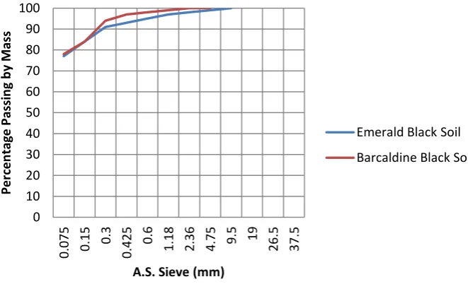
Figure 4.1: Grading Limits for Emerald and Barcaldine Black Soil... 50
Figure 4.2: Amelioration Period – UCS Results ... 55
Figure 5.1: Work Sheet for UCS of Core Samples from Cunningham Highway ... 66
Figure 5.2: Report on Moisture Content for Emerald Soil... 67
Figure 5.3: Report on Particle Size Distribution and Atterberg Limits for Emerald Soil ... 68
Figure 5.4: Report on Grading Limit for Emerald Soil ... 69
Figure 5.5: Report on Apparent Particle Density of Emerald Soil ... 70
Figure 5.6: Report on Moisture Density Relationship (Standard Compaction) for Emerald Soil ... 71
Figure 5.7: Report on Moisture Density Relationship (with Lime @ LD) of Emerald Soil ... 72
Figure 5.8: Report on Lime Demand for Emerald Soil ... 73
Figure 5.9: Report on Organic and Sulphate Content of Emerald Soil ... 74
Figure 5.10: Report on Moisture Content for Barcaldine Soil ... 75
Figure 5.11: Report on Particle Size Distribution and Atterberg Limits of Barcaldine Soil ... 76
Figure 5.12: Report on Grading Limits of Barcaldine Soil ... 77
Figure 5.13: Report on Apparent Particle Density of Barcaldine Soil ... 78
Effectiveness Of Lime Stabilisation On Reactive Soils For Main Roads Page x Figure 5.15: Report on Moisture Density Relationship (with Lime @ LD) for
Barcaldine Soil ... 80
Figure 5.16: Report on Lime Demand for Barcaldine Soil ... 81
Figure 5.17: Report on Organic and Sulphate Content of Barcaldine Soil ... 82
Effectiveness Of Lime Stabilisation On Reactive Soils For Main Roads Page xi
GLOSSARY
Austroads Australian Road Research Board
AS Australia Standard
CaCO3 Calcium Carbonate
CaO Quicklime
Ca (OH)2 Hydrated lime
CO2 Carbon Dioxide
CBR California Bearing Ratio
DD Dry Density
DCP Dynamic Cone Penetrometer
DTMR Queensland Department of Transport and Main Roads
EMC Equilibrium Moisture Content
LL Liquid Limit
LS Linear Shrinkage
MC Moisture Content
MDD Maximum Dry Density
MRS Designation of Queensland Main Roads Standard Specifications
NAASRA National Australian Association of State Road Authorities, now known as Austroads
OMC Optimum Moisture Content
PI Plasticity Index, PI = LL – PL
PL Plastic Limit
Effectiveness Of Lime Stabilisation On Reactive Soils For Main Roads Page 1
1
INTRODUCTION
1.1
Introduction
Various forms of lime stabilisation have been used for thousands of years. Early Roman roads utilised lime as a stabilisation agent and until the invention of Portland cement in the 19th Century, lime was widely used for building construction. The Great Wall of China was constructed using a lime stabilised mortar, as were the original buildings at Port Arthur.
Lime stabilised sub(grades have been used for in excess of 30 years in Ipswich City Council with varying results. In fact, lime stabilised sub(grades were used as a substitute for pavement materials, as there were no naturally occurring suitable pavement materials within the old Ipswich City Council boundaries.
Queensland Department of Transport and Main Roads (DTMR) also trialled lime extensively until the late 70's when it fell from favour. Trials by DTMR have recommenced at various sites since the mid 1990’s.
Queensland has some 180,500km of public road network of which DTMR manages 33,337kms of state(controlled roads comprising the major traffic carrying and strategic roads in the state. Queensland roads are made up of both flexible and rigid pavement types and these pavements are designed to cater for varying traffic volumes, subgrade types and axle loads. The state(controlled road system plays a vital part in the liveability of our cities and rural communities and is valuable for the movement of people and efficient transportation of goods and services throughout the state and country.
New road pavements are usually designed for a life expectancy of at least 20 years; however, a vast majority of the state(controlled roads are located in areas where the insitu material is dominated by reactive soil. Reactive soils are typically clays that demonstrate extensive volume and strength changes at varying moisture content due to their chemical composition. This change in soil volume has shown through history to cause significant structural damage to road pavements, and structural foundations, due at large to the swelling and shrinking that occurs within the soil.
Effectiveness Of Lime Stabilisation On Reactive Soils For Main Roads Page 2 It is believed that stabilising the road pavement with lime is an effective and economic solution when applied in the appropriate environment and quantity.
1.2
The Problem
Early trials of lime stabilised subgrades adopted the Lime Fixation Percentage (Little 1995) which is defined as the percentage of lime which causes the soil’s plastic limit to reach a stable value. The percentage of lime typically added was 2(4% and research has found that these trials were unsuccessful largely due to insufficient quantity of lime being applied to the natural reactive soil and the construction method.
DTMR re(commenced trials of lime stabilised subgrades in 1996 at a couple of sites near Warwick. The Killarney Trial (Warwick – Killarney Road) adopted the Eades and Grim Method (Little 1995) while the Cunningham Highway ( Freestone Creek to Eight Mile Intersection Trial adopted the Thompson Method (Little 1995).
These trials are approaching the later part of their 20 year design life expectancy. The Cunningham Highway trial, which was constructed in 1998, has not shown any sign of deterioration to last inspections and is due for another inspection and testing to check the progress of the Unconfined Compressive Strength (UCS) strength of the road subgrade. This will give an indication whether the subgrade is continuing to increase its strength, remaining stable or starting to decrease in strength after 13 years.
Spreading and mixing lime to stabilise highly reactive clay subgrades is generally completed in two passes. This process is called Amelioration where half the lime dosage is applied in the first pass, left to flocculate for specified timeframe, and then apply the remaining half in the last pass.
Amelioration is necessary in heavy clays as adequate mixing is difficult to achieve in one pass as heavy clays tend to clump together. DTMR presently allow 24 hours between passes to permit the lime to flocculate clay particles and improve workability. Amelioration results in better mixing in the second run and construction become easier.
The major issue with having a 24 hour period for amelioration is it takes a longer time to finish construction. This delays the contractor by having to bring a machine back a second day and the contractor can’t continue construction until after the second pass. This timeframe also delays construction, delays trafficking and exposes the open subgrade to potential weather such as rain for a longer period.
Effectiveness Of Lime Stabilisation On Reactive Soils For Main Roads Page 3
1.3
Research Aims
The aim of this project is to confirm if the UCS of road subgrade has improved or diminished since construction was completed on the Cunningham Highway (Eight Mile Creek to Freestone Creek) trial site and to verify whether 24 hours Amelioration Period for lime flocculation can be reduced and determine what the optimum time required for amelioration.
1.4
Research Approach
The research approach for this study is divided into two parts:
1. Existing pavement UCS strength
• Obtain core samples of existing subgrade material;
• Test UCS of upper, middle and lower layers of the subgrade individually;
• Analyse UCS test results;
• Compare results to previous UCS data.
2. Amelioration Period
• Obtain two samples of black soil using Emerald and Barcaldine soil groups;
• Conduct soil classification testing to obtain moisture content, particle size distribution, atterberg limits, organic content, sulphate content, lime demand, maximum dry density and optimum moisture of both natural soil and soil with lime at lime demand;
• Conduct UCS testing with cure for 28 days @ 23deg / 95% Humidity;
• Test for different amelioration times (0, 6, 12*, 18 and 24 hours).
* Testing will be conducted as close to 12 hours as possible. Access to laboratory may alter this time to 14 hours.
The Amelioration process to be undertaken for the UCS samples is as follows:
Stage 1: Test portion will be mixed with half the total lime needed and with 80% of target water. Test portion will be subjected to half compaction and allowed to cure as per the target amelioration periods.
Effectiveness Of Lime Stabilisation On Reactive Soils For Main Roads Page 4
1.5
Dissertation Outline
This dissertation is organised as follows:
Chapter 2 Literature Review
This chapter reviews and summarises literature relating to the use and construction techniques of lime stabilisation in reactive soils undertaken on roads controlled by the Department of Transport and Main Roads.
Chapter 3 Lime Stabilised Subgrade Strength
This chapter gives an overview of the methodology used to analyse the long term strength gains of lime stabilised subgrade and presents the results of unconfined compressive strength testing
Chapter 4 Amelioration Period
This chapter presents an overview of the methodology used and associated results for the analyse of a range of different amelioration time periods between two(stage lime stabilisation mixing in reactive soils when constructing a pavement subgrade.
Chapter 5 Conclusions and Future Works
Effectiveness Of Lime Stabilisation On Reactive Soils For Main Roads Page 5
2
LITERATURE REVIEW
2.1
Introduction
This literature review covers the background on the properties of lime and reactive soils, use of lime as a stabilising product on road pavements and research carried out to date on the issues faced during design and construction of lime stabilised pavements.
It is important to mention that similar topics have been undertaken by the University of Southern Queensland students over the past few years. The year and topics are outlined below: (
• 2010 – Effective Road Pavement Design for Expansive Soils in Ipswich by Catherine Caunce;
• 2009 ( Alternate Pavement Types on Reactive Soils in the Ipswich Council Area by Jeffrey Crone;
• 2008 ( Investigation of Construction Practices and Test Procedures for Road Pavements on Expansive Subgrades by Kieren Walters;
• 2005 ( Road Stabilisation Issues in Southern District of the Department of Main Roads, Queensland by Elissa Harrison.
Every effort will be made to ensure that relevant data is utilised and this research does not duplicate previous research. The stated outcomes from these previous papers by fellow students indicated that further research could be undertaken in the following areas (with respect to lime stabilisation and clay soils) (:
• Investigation into the cause of pavement failures;
• Advantages of performance based testing over traditional empirical testing;
• Determination of the strength gain relationship between lime stabilization and black soils;
• Longer term testing of stabilisation efforts;
• Trial test methods such as soil suction during seasonal peaks to determine the active depth of expansive soils;
• Classification of clays using various methods.
2.2
Properties of Lime
Lime is produced from Limestone (Calcium Carbonate CaCO3) which occurs naturally
Effectiveness Of Lime Stabilisation On Reactive Soils For Main Roads Page 6 Lime stabilisation in road pavements requires a more reactive form of lime. This is achieved with quicklime or hydrated lime.
2.2.1 Quicklime
Quicklime (CaO) is formed by heating calcium carbonate (CaCO3) at high temperatures
until carbon dioxide is driven off.
CaCO3 + Heat (~1315°C) → CaO + CO2
Quicklime can be manufactured in varying sizes from quite fine to very coarse. Some of the different types available are Lump Lime, Pebble Lime, Granular Lime and Pulverised lime (Little 1995).
Quicklime has a high heat of hydration (S H = (15.6 kcal/mol) which makes it difficult to handle and store. In humid climates it may be necessary to slake the lime immediately to form hydrated lime. It is of a caustic nature and must be handled with caution because it will corrosively attack equipment and can cause severe skin burns (Metcalf & Ingles 1972).
2.2.2 Hydrated Lime
Hydrated lime (Ca (OH)2) is a fine dry powder and is formed by “slaking” quicklime
(CaO) by the addition of water.
CaO + H2O → Ca(OH)2 + Heat
Hydrated lime is less sensitive to humid climates and therefore makes handling and storage easier than with quicklime. However, prolonged exposure can still cause skin irritations.
For lime stabilisation, the quantity of calcium hydroxide is the active component that reacts with the subgrade or pavement material. In the laboratory, hydrated lime is used to determine the amount of lime to achieve the desired material attributes. However, in construction, quicklime (calcium oxide) is often used which if added at the laboratory determined application rate will result in an increased amount of calcium hydroxide being available. Table 2(1 (Austroads 2006) indicates that quicklime has approximately 30% more effective lime for stabilisation than hydrated lime (i.e. equivalent Ca(OH)2/unit mass when slaked). This needs to be taken into account in the mix design
Effectiveness Of Lime Stabilisation On Reactive Soils For Main Roads Page 7
Table 2+1: Properties of quicklime and hydrated lime (assuming pure lime)
Pure lime is calcium carbonate containing 40% calcium and no magnesium, whilst good commercial agricultural lime contains 35%–38% calcium and very little magnesium.
2.3
Properties of Reactive Soils
Reactive or expansive soil is described as any soil that consist of clays which will expand or contract with a variation of moisture content (West 1995). Three of the main types of clay minerals that are found in Australian soil are:
• Kaolinite;
• Illite;
• Montmorillonite.
Kaolinite is a low plastic clay and tends to be a non(swelling. Illite is an expansive clay of medium plasticity and low permeability. The most active of the three clays is Montmorillonite which is highly expansive, highly plastic and is extremely impermeable.
The in(situ moisture content of a soil, and its consistency, can be useful in determining the shear strength, compressibility and bearing capacity of the soil. When the soil’s natural moisture level is near the liquid limit (LL), the soils will exhibit low strength. However, when the moisture content is near the plastic limit (PL), firmness is more apparent and greater strengths are exhibited.
Lime reacts more quickly with Montmorillonitic clays than with Kaolinitic clays. The difference may amount to a few weeks (Metcalf & Ingles 1972). The addition of lime will improve soil properties such as plasticity index (PI) reduction in Montmorillonitic clays however, this may not occur in Kaolintic clays.
Effectiveness Of Lime Stabilisation On Reactive Soils For Main Roads Page 8
2.4
Chemistry of Lime Stabilisation
2.4.1 Soil Modification
[image:20.595.116.386.546.758.2]There has been a lot of work done to understand the processes of lime stabilisation. It is now accepted that small amounts of lime modify the properties of soils through a rapid rate process of ion exchange and flocculation or edge to face reorientation of the clay plate(like particles. Refer Figure 2.1.
Figure 2.1: Flocculation + Reorientation of Clay Particles
Rapid pozzolanic reactions may also occur during the process. Pozzolanic reaction is discussed further in Section 2.4.3. These reactions cause a reduction in the PI and volumetric change which improves the workability and shear strength of the soil.
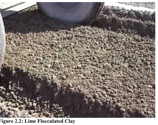
After initial mixing, the calcium ions (Ca++) from hydrated lime migrate to the surface of the clay particles and displace water and other ions. The soil becomes friable and granular, making it easier to work and compact (Figure 2.2). At this stage the Plasticity Index of the soil decreases dramatically, as does its tendency to swell and shrink. The process, which is called flocculation or agglomeration, generally occurs in a matter of hours.
Effectiveness Of Lime Stabilisation On Reactive Soils For Main Roads Page 9 Soil modification using low levels of lime can be a most economic construction expedient. It permits the use of heavy construction machinery to be used in wet conditions when it is necessary to dry out saturated materials, to bridge across poor subgrade soil or to provide a stable working platform for placement and compaction of pavement layers over the subgrade.
However subgrades modified with small amounts of lime may be more susceptible to moisture entry due to increased permeability, to such an extent that these initial strength gains may be short term and can be reversed through leaching of calcium from the subgrade upon water entry.
Extensive research conducted by McCallister and Petry (1990) demonstrated that the permeability of soils increased significantly after initial lime additions, then decreased as further concentrations were added. These effects seem to be due to flocculation of the clay plates and the development of some pozzolanic reaction products. The resultant soil structure is an open matrix.
Such effects have been confirmed by recent local testing and are suspected to be the main cause of some unsatisfactory historical experiences due to the addition of inadequate amounts of lime.
It is recommended that lime modification should be used with caution, particularly if subgrades are likely to be exposed to water entry (e.g. low lying areas). Successful usage of low concentrations of lime has often been associated with well(drained embankments, or subgrades protected from moisture ingress by extensive subsoil drainage systems.
2.4.2 Soil Stabilisation
If there are sufficient amounts of calcium and pozzolans (silica and alumina particles) available in the soil then the soil will continue to gain strength though the stabilisation process. The silica and alumina particles only become available for pozzolanic reactions to occur in high pH environments. Therefore there must be a sufficient amount of lime available after soil modification to elevate the pH to at least 12.4.
Effectiveness Of Lime Stabilisation On Reactive Soils For Main Roads Page 10
2.4.3 Pozzolanic Reactions
“A pozzolan is defined as a finely divided siliceous or aluminous material which in the presence of water and calcium hydroxide will form a cemented product. The cemented products are calcium(silicate hydrates and calcium(aluminate hydrates” (Little 1995).
The following equations represent the pozzolanic reactions:
Ca++ + OH( + Soluble Clay Silica → Calcium Silicate Hydrate (CSH) Ca++ + OH( + Soluble Clay Alumina → Calcium Aluminate Hydrate (CAH)
In the case of montmorillonite clays (generally present in black soil), the pozzolanic reaction does not provide a permanent effect until enough cation exchange has occurred to saturate the layers between the clay minerals.
2.5
Design
DTMR Pavement Design Manual requires all new flexible pavements to be designed for a design life of at least 20(40 year, depending on volume of traffic. All rehabilitation treatments shall be designed for a design life of at least 20 years.
The percentage of lime required to reduce the plasticity index and improve workability is known as the ‘Lime Fixation’ percentage. The ‘Lime Fixation’ percentage is the maximum percentage of lime which causes a change in the plasticity index. Beyond this percentage no further change in plasticity index will occur.
The Mixture Design and Testing Protocol (Little 1999, 2000) is designed to produce a mixture that possess the desired structural properties and durability in a pavement layer. The procedure measures engineering properties that are critical to the performance of the lime(stabilised mixture as a structural layer in a pavement system.
DTMR currently use the Lime Demand Test to establish whether a soil is reactive to lime and to determine the amount of lime required to “satisfy cation exchange and short term reactions” (DTMR 2007).
The long term reactivity and durability of the soil is further assessed by conducting 28( day Unconfined Compressive Strength (UCS) Testing. Long Term Reactivity is determined by calculating the UCS at Lime Demand minus the UCS at zero percent lime. A soil is considered non reactive when this value is less than 0.35MPa and reactive when greater or equal to 0.35MPa (DTMR 2007).
Effectiveness Of Lime Stabilisation On Reactive Soils For Main Roads Page 11 Sound specifications such as Main Roads Standard Specification for Insitu Stabilised Subgrades using Quicklime or Hydrated lime (DTMR 2006) use best construction practice for lime stabilisation. It also gives designers the confidence that construction would be carried out to ensure that lime reactions develop and sufficient compaction of the stabilised materials is achieved (AustStab 2008).
Research indicates that accelerated curing (at higher than field temperatures) can alter the mechanism of normal pozzolanic reaction. This is the reason why curing for less than 28 days before testing UCS cylinders is not recommended.
Laboratory testing is always carried out using hydrated lime. If quicklime is used in the field, which is the common practise, the laboratory design dosage will need to be decreased (to compensate for the increased concentration of CaO in quicklime). The level of impurities will depend on the source of the quicklime and the application rate should be adjusted to compensate for impurities.
2.6
Properties and Characteristics of Lime+Treated Soils
In general, most fine(grained soils exhibit improved plasticity (i.e. lower plasticity), workability and volume change characteristics when mixed with lime. An attempt has been made to summarise these effects on the soil due to addition of lime as follows:
2.6.1 Compaction Characteristics
Effectiveness Of Lime Stabilisation On Reactive Soils For Main Roads Page 12
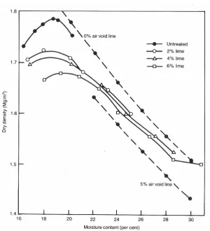
Figure 2.3: Effect of lime content on the moisture content / dry density relation
Source: (Littleton 1988)
The shift in density and optimum moisture content is evidence of the physical changes that occur during lime treatment. If a mixture is allowed to cure and gain strength prior to compaction, a further reduction in the maximum dry density and an additional increase in optimum moisture content may be noted. It is important that the appropriate moisture(density curve, in terms of percent lime used and time of curing, be used for field control purposes.
2.6.2 Plasticity and Workability
Effectiveness Of Lime Stabilisation On Reactive Soils For Main Roads Page 13
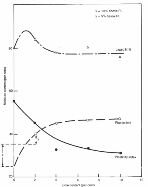
Figure 2.4: Effect of the addition of lime on the plasticity properties of London Clay
Source: (Sherwood 1993)
Figure 2.5: Effect of lime and cement on a clay soil after 10 minutes mixing in a laboratory mixer (initial moisture content 29%)
[image:25.595.116.358.57.364.2]Effectiveness Of Lime Stabilisation On Reactive Soils For Main Roads Page 14
2.6.3 Swell Potential
Soil swell potential and swelling pressure are normally significantly reduced by lime treatment. These reduced swell characteristics are generally attributed to a decreased affinity for water of the calcium(saturated clay, a reduction in the number of inter( corrected voids, and the formation of a cementitious matrix that resists volumetric expansion.
2.6.4 Strength
The strength of lime(soil mixtures can be evaluated in many ways. The UCS test is the most popular procedure and CBR tests are used to a lesser extent. The strength is a function of soil type, lime type, lime percentage and the curing conditions (i.e. time and temperature). The difference between the compressive strengths of the natural and lime(treated soil has been used as an indication of the degree to which the soil(lime reactions have proceeded. A substantial strength increase indicates that the soil is reactive with lime and can probably be stabilised to produce a higher quality road building material.
The major effect of lime on the shear strength of a reactive fine(grained soil is to produce a substantial increase in cohesion with some minor increase in the angle of internal friction.
At the low confining pressures normally considered to exist in a flexible pavement structure, the cohesion increase is of the greatest significance. It is apparent that large shear strengths could be developed in cured soil(lime mixtures.
The tensile strength of a lime(soil mixture increases as the UCS increases. Two test procedures are commonly used to measure the tensile strength: ( the indirect tensile test and the flexural beam test. The ratio of indirect tensile strength to UCS is approximately 0.13 which can then be used for normal design purposes (Little 1987).
The common method for evaluating the flexural tensile strength is the flexural beam test as this value can be related to the stabilised slab which bends under the action of traffic loading in the field. A realistic estimate of the flexural strength (modulus of rupture) is 0.25 times the cured UCS (Little 1987).
2.6.5 Deleterious Materials
Effectiveness Of Lime Stabilisation On Reactive Soils For Main Roads Page 15 Organic molecules ‘can absorb calcium cations or interact with soil exchange sites and hence prevent them from reacting with the soil as they normally would to produce cation exchange and pozzolanic reaction’ (Little 1995). Lime stabilisation relies on an increase in the pH of the soil for pozzolanic reactions to occur. Depending on the type and amount of organic material present in the soil, it may retard or completely inhibit the change in pH (Sherwood 1993). Lime stabilisation of soils with greater than one percent of organic materials may still be possible with the addition of higher percentages of lime.
Any sulphates that are present in the soil or water can be harmful to the lime stabilisation process due to the formation of calcium(sulphate(aluminate(hydrate crystals. If calcium(sulphate(aluminate(hydrate crystals form after compaction it can destroy the pavement because it will result in heaving of the stabilised layer (Little 1995).
2.6.6 Permeability
Permeability of some lime reactive soils will tend to initially increase upon lime treatment. The initial increase will then usually be followed by a decrease in permeability, although it will often remain significantly higher than the level prior to lime treatment. However, it has also been shown that curing may have a positive effect on permeability. Together, curing and ongoing pozzolanic reactions can decrease the permeability of some lime stabilised soils. In some instances the permeability will decrease to approximately that of the natural soil (Little 1995).
Effectiveness Of Lime Stabilisation On Reactive Soils For Main Roads Page 16
2.7
Stabilised Subgrade Construction
The construction steps involved in stabilization and modification are similar. Generally, stabilization requires more lime and more thorough processing and job control than modification.
Basic steps include:
• scarifying or partially pulverizing soil; • spreading lime;
• adding water and mixing;
• compacting to maximum practical density; and
• curing prior to placing the next layer or wearing course.
In the past it was common practice to scarify before spreading. Today, because of the availability of superior mixers, lime is often applied without scarification. Lime trucks can also negotiate the roadway more readily if it is compacted, rather than scarified, particularly on wet soils.
Mixing of the lime is undertaken by in(place mixing, plant mixing or pressure injection. The most common method is in(place mixing which involves mixing the lime with the existing material at the construction site.
Adequate mixing is absolutely essential to achieve satisfactory results in lime stabilisation. Whilst some soils may only require one(stage mixing, heavier and more plastic soils require two(stage mixing.
The two(stage process consists of preliminary mixing, moist curing for a period of time and final mixing or remixing. In the preliminary mixing operation, the objective is to distribute the lime throughout the soil and thereby allow the lime to start breaking down the clay particles. In order to optimise the chemical reactions of cation exchange and pozzolanic reactivity it is essential to leave the mixed soil to ameliorate or “mellow” for a period of time. Generally after a 24 to 48 hour delay (Little 1995) the clay becomes friable enough to easily allow better mixing in the final mixing.
2.7.1 Department of Main Road Construction Procedures
Department of Transport and Main Road Technical Specification MRTS07A (DTMR 2006) specifies the following construction procedures for lime stabilising a pavement subgrade.
2.7.1.1 GENERAL
Effectiveness Of Lime Stabilisation On Reactive Soils For Main Roads Page 17 The stabilising agent shall be spread using a purpose(built spreader and the stabilising agent and water shall be incorporated into the material using a reclaimer/stabiliser or stabiliser.
Alternatively, a reclaimer/stabiliser with a calibrated integrated spreader/applicator may be used to incorporate the stabilising agent and water directly into the material to be stabilised. Where a reclaimer/stabiliser with calibrated integrated spreader/applicator is used, quicklime shall not be used as the stabilising agent.
2.7.1.2 DAY 1
A single lime pass at a rate of up to half the required rate shall be applied. Where quicklime is spread over the subgrade, it shall be slaked. In situations where hydrated lime is used, slaking is not required before mixing the stabilising agent into the soil. The hydrated lime or lime slurry formed from the slaking of quicklime shall then be mixed into the material. The depth of mixing shall not exceed 90% of the specified stabilisation thickness. The material shall be lightly rolled to seal the surface prior to the completion of work on that particular day.
2.7.1.3 DAY 2
After the overnight amelioration period, the balance of the required lime shall be spread. Where quicklime is spread over the subgrade, it shall be slaked. In situations where hydrated lime is used, slaking is not required before mixing the stabilising agent into the soil. The hydrated lime or lime slurry formed from the slaking of quicklime shall then be mixed into the material. Notwithstanding this, a minimum of two mixing passes shall be completed.
2.7.1.4 SPREADING OF STABILISING AGENT
Lime shall be spread at a maximum spread rate of 12 kg/m2. The number of passes shall be calculated to comply with this requirement. The stabilising agent shall be uniformly spread over the insitu material at a controlled rate (mass per unit area, kg/m2).
Witness Point
The total rate of spread shall be such that the stabilising agent spread rate for the compacted material is within the specified tolerances.
Effectiveness Of Lime Stabilisation On Reactive Soils For Main Roads Page 18 After each spreading run at least one mixing run, trimming and/or compaction, as required, shall be completed. Further mixing operations between spreading runs shall be completed.
2.7.1.5 SLAKING
Quicklime shall be slaked with sufficient water to allow complete hydration such that the material remains friable after slaking and no further exothermic reaction occurs when further water is added to the lime.
All through traffic shall be stopped during any slaking operation.
2.7.1.6 MIXING
Mixing shall be achieved using a reclaimer/stabiliser or stabiliser. Where quicklime is used as the stabilising agent mixing shall not commence until slaking is complete.
On day two, all lime spread shall be mixed into the soil within 6 hours of each application.
The depth of each mixing pass, except the final mixing pass, shall not exceed 90% of the full depth of stabilisation specified. The final mixing pass shall be to the full depth of stabilisation specified. Mixing shall proceed until all material other than stones can pass a 19 mm AS sieve, at least 60% of such material can pass a 9.5 mm AS sieve and the lime is uniformly mixed through the soil. Notwithstanding this the minimum number of mixing passes shall be two.
The distribution of the stabilising agent and water shall be uniform throughout the full depth, and over the entire area, of the material to be stabilised. The moisture content shall be adjusted as necessary during the mixing process to maintain moisture content of between 97% and 101% of OMC (optimum moisture content) of the stabilised soil as determined by tests using standard compactive effort.
Water shall be added by means of a controlled pressure feed distribution system located inside the mixing chamber of the reclaimer/stabiliser or stabiliser. This system shall be capable of spraying varying rates across its width.
Where test results or visual inspections indicates that any of the requirements stated in this Clause have not been met, additional mixing passes shall be carried out to improve the uniformity of the –
a) Materials to be stabilised;
Effectiveness Of Lime Stabilisation On Reactive Soils For Main Roads Page 19 After each spreading run, mixing, trimming and/or compaction, as required, shall be completed.
2.7.1.7 TRIMMING BEFORE COMPACTION
After completion of stabilisation and before compaction commences, the surface shall be trimmed to approximately the alignment, heights and shapes specified for the completed work, and any depressions shall be filled with additional stabilised material that is mixed and placed within its allowable working time.
2.7.1.8 COMPACTION
Light compaction of the stabilised material shall be completed after each application of lime has been incorporated into the material. This shall be carried out using an appropriate roller that is capable of achieving relatively uniform compaction over the depth of the stabilised layer.
Final compaction shall be completed within the allowable working time and the stabilised layer shall be compacted.
2.7.1.9 TRIMMING AFTER COMPACTION
No marks caused by a pad foot or other roller shall remain on the surface after final trimming.
All trimming shall involve cutting to waste. All material cut to waste shall be disposed of in accordance with Clause 11 of MRTS01 Introduction to Technical Standards.
2.7.1.10 PERIOD FOR COMPACTION AND TRIMMING
Compaction and trimming shall be completed within the allowable working time.
2.7.1.11 CURING
Effectiveness Of Lime Stabilisation On Reactive Soils For Main Roads Page 20
2.7.1.12 PROTECTION
The surface of the compacted layer shall be kept moist, in good order, in good condition and free from contamination until an overlying pavement layer or a sprayed bituminous surfacing with cover aggregate is placed. Construction or other traffic shall not use a compacted layer where damage to the surface may occur. Placement and compaction of any subsequent layer shall be carried out within 48 hours of density testing subject to the stabilised later complying with all specified requirements.
2.7.1.13 CONDITIONS UNDER WHICH STABILISATION SHALL NOT PROCEED
The entire stabilisation process shall not proceed in any of the following situations – a) during rainfall;
b) when rainfall appears to be imminent;
c) during periods when the wind is strong enough to cause particles of the stabilising agent to become airborne;
d) during conditions that may result in the work causing nuisance or danger to people, property, the environment, or live stock;
e) when the pavement temperature, measured 50 mm below the surface, drops below 10ºC; or
f) when the air temperature, measured in the shade, exceeds 40ºC.
2.8
Amelioration
Two(stage mixing process consists of preliminary mixing, moist curing for a period of time and final mixing or remixing. In the preliminary mixing or first application, the objective is to distribute the lime throughout the soil and allowing the amelioration or mellowing operation to take place.
Highly reactive clay soils require a high percent of lime to be mixed for effective soil modification. The recommended maximum spreading rate for hydrated lime is 20kg/m2 and for quicklime is 12 to 15kg/m2 (AustStab 2008). This generally requires the mixing to occur in two passes.
This two(stage mixing process is now standard DTMR practice which involves applying half the lime dosage in the first pass then the remaining half is applied in the second pass after waiting a specified amelioration time period.
Effectiveness Of Lime Stabilisation On Reactive Soils For Main Roads Page 21 Conversely, a mellowing time period of 24 to 72 hours or more is indicated in Dallas Little’s Handbook for Stabilisation of Pavement Subgrades and Base Courses with Lime (Little 1995).
Amelioration is necessary in heavy clays as adequate mixing is difficult to achieve in a single pass as heavy clays tend to clump together. Historically, amelioration was needed to breakdown clay so that low capacity rotary hoes could work in the clay soil environment. This problem has largely been overcome with modern purpose built machines.
The two(stage mixing standard has been set by the maximum quantity of lime, but in some circles is considered conservative. It is important to note that subgrades are the foundation for roads which will be buried for a long time.
Allowing 24 hours between passes permits the lime to flocculate clay particles and improve workability. Amelioration results in better mixing in the second run and construction becomes easier.
The major issue with a 24 hour period for amelioration is it takes a longer time to finish construction. This delays the contractor by having to bring a machine back a second day or having machinery sitting idle which is expensive especially on small projects. Construction is delayed as the contractor can’t continue construction until after the second pass.
During the amelioration period the open subgrade is exposed to potential weather such as rain for a longer period. The subgrade soils mixed with lime in the first pass become more permeable and if rain falls on the subgrade, water infiltration will become a problem. This will delay construction as this wet material is difficult to compact and may even require the stabilisation process to recommence.
Another issue is if the mixing machine breaks down, a second machine would have to be sourced within 24 hours which can be difficult in remote areas. This would extend construction delays and possibly require the lime stabilisation to be started again.
Effectiveness Of Lime Stabilisation On Reactive Soils For Main Roads Page 22
2.9
Pavement Performance
The material properties of lime(stabilised soils, as related to their overall pavement performance, can be divided into four categories (Little 1999):
2.9.1 Strength
The most obvious improvement in a lime reactive soil is strength gained over time. The various strength parameters impacted by pozzolanic reactions that occur include UCS, tensile strength, flexural strength and CBR.
2.9.2 Resilient Modulus / Stiffness
Concurrent with the strengthening of a soil brought about by pozzolanic reactions, are changes in the stress(strain relationship of the material (Little 1999). Materials in the laboratory (repeated(load triaxial and indirect tensile test) and in the field (impulse deflection test and vibrational test) both confirm significant increases over time in the resilient properties of lime treated materials.
2.9.3 Fracture and Fatigue
Flexural fatigue strength is related to the number of loads that can be carried by a material at a given stress level and is an important consideration in the evaluation of lime(soil mixtures. The strength gain effects produced by pozzolanic reactions are often substantial for reactive soils.
2.9.4 Durability
The ability of lime stabilised materials to resist the detrimental effects of moisture and freeze(thaw cycling over time has been evaluated in several ways in both the laboratory and field. The results of these evaluations have often shown only slight detrimental effects from the environment on the levels of strength / stiffness produced by the addition of lime.
2.10
Lime Stabilisation in Queensland
Effectiveness Of Lime Stabilisation On Reactive Soils For Main Roads Page 23 The Queensland Department of Main Roads extensively trialled lime stabilisation in roadwork’s until the late 1970’s when it fell from favour. A couple of projects that brought about the downfall of lime stabilisation were the Gladfield project in the Border District and the Palmerston Highway project in the Peninsula District. The design of the lime content during this era was based on the Lime Fixation Percentage method.
Current research into lime stabilisation has found that the Lime Fixation method grossly underestimates the percentage of lime actually required for stabilisation. The lime percentages applied during the late 70’s were only enough to promote soil modification. Leaching of the lime during wet conditions would have rapidly reversed any soil improvements.
Research into lime stabilisation was not again conducted in Queensland until after the 1996 Transport Technology Forum. A steering committee was formed to review past lime stabilisation projects and to oversee the design and performance of two new trial projects near Warwick, Queensland. The steering committee consisted of representatives from Industry, Local Government, DTMR Transport Technology and DTMR Border District.
The paper ‘Update on Lime Stabilisation’, written by Peter Evans (Evans 1997) reports on the design and performance of the Killarney Project and the design of the Cunningham Highway ( Freestone Creek to Eight Mile Intersection Project. Evans reports on the performance of the Freestone Creek to Eight Mile Intersection Job in a later paper, ‘Rethink of the Design Philosophy of Lime Stabilisation (1998)’. At the time of Evans’ paper (Evans et al. 1998) coming to print, the DTMR Technology and Environment Division were commissioning a review into the research project to determine whether it had been a success.
The Killarney Project
Two laboratory methods were investigated prior to deciding on the lime percentage for the Killarney Project. The first method investigated was the Lime Fixation Method. Data showed that 3(4% of lime was required to stabilise the soil’s plastic limit. Data from the second method, the Eades and Grim Method showed that 4 percent of lime was required to reach a pH of 12.4 and 8 percent was required to stabilise the pH level (Eades & Grim 1960).
Effectiveness Of Lime Stabilisation On Reactive Soils For Main Roads Page 24 Sections of the project were trialled with concentrations of 3 to 6 percent quicklime in an effort to determine the actual lime demand percentage. After 9 months of monitoring by the steering committee the following conclusions were made:
• Lime stabilisation was an effective method for expediting the construction process during wet conditions;
• There was a noticeable difference in appearance and insitu CBR between the 3% and 6% lime stabilised sections. The 6% quicklime section had an insitu CBR of almost triple that of the 3% stabilised section.
In Evans’ paper it was proposed that the steering committee continue performing deflection testing on the pavement and monitoring its long(term performance. Assessments will continue to be made of the modulus to assess whether it improves over time.
Cunningham Highway + Freestone Creek to Eight Mile Intersection
The Freestone Creek to Eight Mile Intersection project consisted of widening a 4km section of the Cunningham Highway, 13 km north from Warwick. Due to the presence of highly expansive clays it was necessary to provide a deep pavement to bridge over the poor subgrade. However, this was not feasible due to being constrained by the 300mm existing embankment. A more viable option was to lime stabilise the subgrade to a depth of 300mm.
Following recommendations in the Handbook for Stabilization of Pavement Subgrades and Base Courses with Lime (Little 1995), 28(day UCS tests were carried out for various lime contents. This laboratory test method is referred to as the Thompson Method.
During laboratory testing for this project, comparisons were made between the Lime Fixation, Eades and Grim and Thompson methods. Both the Lime Fixation and Eades and Grim Methods demonstrated lime percentages that were considerably less than the Thompson Method. After applying the hydrated lime to quicklime conversion factor and allowing for losses, 8% quicklime was adopted in the design. A 20m section of subgrade at the Eight Mile end of the works was not stabilised so that comparisons of UCS could be made.
Six weeks after the project was completed deflectometer testing was conducted on the pavement using a 40kN falling weight. Analysis showed that the modulus of the stabilised subgrade was significantly higher than that of the overlying base course material.
Effectiveness Of Lime Stabilisation On Reactive Soils For Main Roads Page 25
2.11
Chapter Summary
Subgrades are the foundation upon which road pavements are built. Pavement failures largely tend to occur as a result of problems with the subgrade. They are typically due to loss in strength which can be attributed to the poor strength of reactive clay material and moisture infiltration into the pavement material from the insitu clay material below or ingress from the top or side of pavement.
Initial results from the Cunningham Highway lime stabilisation trial project undertaken by DTMR tended to indicate that strength gains were permanent and ongoing. There is not sufficient data to confirm whether strength gains are long term. This research will undertake testing and analysis to determine whether the UCS of the subgrade has maintained an acceptable strength on the Cunningham Highway lime stabilised trial site.
Effectiveness Of Lime Stabilisation On Reactive Soils For Main Roads Page 26
3
LIME STABILISED SUBGRADE STRENGTH
3.1
Background
Subgrade stabilisation was completed on the Freestone Creek to Eight Mile Intersection section of the Cunningham Highway in 1998. The project consisted of widening a 4km section, however as a result of the presence of highly expansive clays, the most viable option was to lime stabilise the subgrade to a depth of 300mm.
The pavement design overlaying the stabilised subgrade consisted of 300mm of gravel and a wearing surface of 100mm asphalt. A further 100mm of asphalt was laid to the full width of road in 2005. Visual evidence indicates the pavement is performing well.
Figure 3.1 shows the lime being spread to the subgrade of the widening on the Cunningham Highway trial.
Figure 3.1 Lime Spreading on Widening to Cunningham Highway Trial Project
3.2
Design of Lime Content
Effectiveness Of Lime Stabilisation On Reactive Soils For Main Roads Page 27 The design method results are summarised as follows:
a) Lime Fixation Percentage indicates the percentage of lime to cause the plastic limit to stabilise (refer to Figure 3.2).
b) Lime Demand indicates the percentage of lime required to achieve pH of 12.4 (refer to Figure 3.3).
c) Strength indicates the percentage of lime required to achieve a minimum 28 day UCS of 1.5MPa in accordance with Thompson’s Method (refer to Figure 3.4).
Figure 3.2: Lime Fixation Percentage
Effectiveness Of Lime Stabilisation On Reactive Soils For Main Roads Page 28
Figure 3.4: Thompson’s Strength Method
For the Thompson method, the peak 28 day UCS results occur with 9% Hydrated Lime (Figure 3.4). Applying a conversion factor of 0.757 (adjustment of hydrated lime to quicklime used in the field), this equates to 6.8% quicklime. Allowing an additional 1% for variations, the design adopted was 8% quicklime.
3.3
Subgrade Strength at Construction
Deflectometer tests were conducted using the 40kN Heavy Weight Deflectometer, approximately 6 weeks following job completion, and these were back analysed from deflection data to determine the Modulus. The results of this analysis are shown in Figure 3.5 and indicate that the stabilised subgrade was in fact stronger than base course gravel (CBR 80) which is used as the top layer in all DTMR road pavements.
The UCS values are typically derived by dividing the Modulus values by 1000, hence the UCS of the stabilised subgrade ranged from approximately 0.6 to 1.0MPa.
Effectiveness Of Lime Stabilisation On Reactive Soils For Main Roads Page 29
Figure 3.5: Comparison of Modulus
UCS cylinders were taken at various sections during the stabilisation process and tested during the initial twenty six months following completion. Results indicate that the initial strength gains appeared to be permanent and ongoing. This is clearly shown in Figure 3.6.
Effectiveness Of Lime Stabilisation On Reactive Soils For Main Roads Page 30
3.4
Present Subgrade Strength
The aim of this part of the research was to determine the strength of the stabilised subgrade in comparison to previous testing. This would confirm whether the strength still achieves the minimum requirement of 1.5Mpa. This investigation includes the following:
• Obtain core samples of existing subgrade material;
• Test UCS of upper, middle and lower layers of the pavement individually;
• Analyse UCS test results;
• Compare results to previous data.
3.4.1 Methodology
In consultation with DTMR staff a site was chosen to obtain undisturbed cylindrical samples suitable for UCS testing. This site was located at the eastern end of the section and the coring was undertaken on 16 June 2011 by DTMR Soils Laboratory staff from the Southern Districts office.
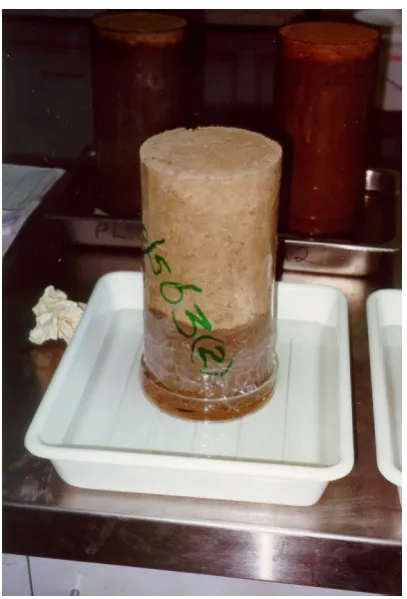
It was decided to take the core samples from the shoulder to minimise impacts on the existing pavement in the travel lanes of the highway. The process involved scarifying the existing asphalt (Figure 3.7) then excavating the pavement gravels to the subgrade. Six core samples were taken from the subgrade (Figure 3.8) for laboratory testing to test three layers within the subgrade material. These were top, middle and bottom sections of the core samples.
Figure 3.7: Asphalt Excavation Figure 3.8: Core Holes in Subgrade
Effectiveness Of Lime Stabilisation On Reactive Soils For Main Roads Page 31
Figure 3.9: Core Sample (End View) Figure 3.10: Core Sample (Side View)
DTMR laboratory specimens are typically compacted in standard compaction moulds with length(to(diameter (L/D) ratio approximately equal to 1. This ratio will influence the UCS values that are obtained from core samples, so it was important that the post construction core samples should have a similar L/D ratio for the values to be relative.
3.4.2 Laboratory Testing
Laboratory testing was performed by the DTMR Materials Section in Herston, Brisbane on 21 June 2011 in accordance with DTMR Material Testing Manual (DTMR 2010).
The core samples were cut to provide representative samples for the top, middle and bottom portions of selected core samples. The core sample details are indicated in Table 3(1.
Table 3+1: Core Sample Details
Core No. (Location) Core Diameter Mm Core Height mm
L/D Insitu
Density T/m3
Mass
Kg
2 (Top) 143 127 0.89 1.844 3.762
2 (Bot) 143 134 0.94 1.794 3.861
6 (Mid) 143 199.4 1.39 1.760 5.635
Unconfined Compressive Strength of Compacted Material was undertaken generally in accordance with Q115 – 2010 from the Department of Main Roads Materials Testing Manual (DTMR 2010).
Effectiveness Of Lime Stabilisation On Reactive Soils For Main Roads Page 32 This method was developed in(house by DTMR using techniques evolved through internal departmental research investigations.
The steps to determine the UCS of core samples were as follows:
• Determine the average diameter (D) of each test specimen to the nearest 0.1 mm from two diameters measured at right angles to each other;
• Place the test specimen centrally on the lower platen of the CBR machine such that the top of the specimen is uppermost;
• Apply a compressive force to the specimen and record the maximum applied force (F) in kN;
• Using the achieved compaction moisture content, calculate the achieved compacted dry density and the achieved relative compaction for each specimen as detailed in Test Method Q145A;
• Calculate the unconfined compressive strength for each specimen to the nearest 0.05 MPa as follows:
=
1273 ∗
Where,
UCS = unconfined compressive strength (MPa) F = applied force at failure (kN)
D = average diameter of specimen (mm)
The UCS formula above is identical to the stress formula which was used to obtain results in this testing.
=
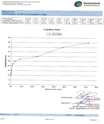
In addition to the UCS test, it was decided to conduct a Capillary Rise test on the core samples to determine the water absorption, swell and capillary rise of water in the compacted stabilised subgrade materials. This test was undertaken in accordance with AS 5101.5 – 2008: Absorption, swell and capillary rise of compacted materials.
3.4.3 Results
Effectiveness Of Lime Stabilisation On Reactive Soils For Main Roads Page 33
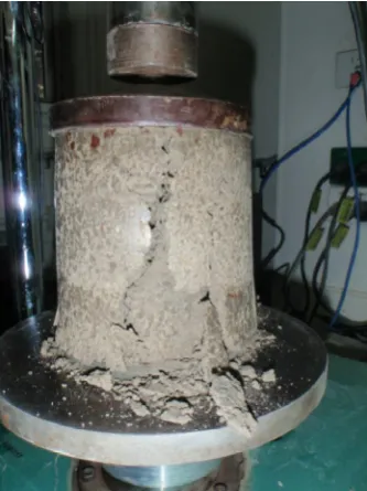
Figure 3.11 Test Specimen Compressed in CBR Machine until Failure
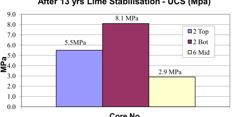
Compressive force results obtained are summarised in Table 3(2 and pictorially represented in Figure 3.12 below.
From these results it can be seen that the target 28 day strength of 1.5MPa was easily achieved.
Table 3+2: Core Sample Strength Results
Core No. (Location)
Core Area mm2
Maximum Force kN
UCS MPa
2 (Top) 16061 87.97 5.50
2 (Bot) 16061 129.9 8.10
[image:45.595.142.309.57.280.2]Effectiveness Of Lime Stabilisation On Reactive Soils For Main Roads Page 34
Figure 3.12: Unconfined Compressive Strength Results
3.4.4 Long Term Unconfined Compressive Strength
[image:46.595.118.526.72.278.2]The UCS test results from June 2011 were averaged and collated against previous UCS test result data which were also averaged between sections. The analysis of these results is shown in Figure 3.13.
Figure 3.13 Strength after 13 Years
Analysis of test results from June 2011 shows that the average UCS has increased to approximately 5.4MPa compared to strength of approximately 4.1MPa two years after construction. 0.0 1.0 2.0 3.0 4.0 5.0 6.0 7.0 8.0 9.0
Core No.
M
P
a
After 13 yrs Lime Stabilisation UCS (Mpa)
2 Top 2 Bot 6 Mid 5.5MPa 8.1 MPa 2.9 MPa 0 1 2 3 4 5 6
0 1 2 3 4 5 6 7 8 9 10 11 12 13 14
U C S ( M p a )
Effectiveness Of Lime Stabilisation On Reactive Soils For Main Roads Page 35 The current strength is still well above DTMRs required 1.5MPa and appears to be on target to reach the expected design life of 20 years and possibly well beyond.
3.4.5 Capillary Rise
[image:47.595.114.318.239.539.2]An assessment was also undertaken of the long term effect on Capillary Rise. There was some sign of visual moisture rising up the side of samples, as seen toward the bottom of sample in Figure 3.14. Moisture appeared to rise all the way to the top of one sample.
Figure 3.14: Capillary Rise Test
Effectiveness Of Lime Stabilisation On Reactive Soils For Main Roads Page 36
Figure 3.15: Capillary Rise Test Result
Deterioration of road conditions in reactive soils mostly results from water entering the pavement gravels which weakens the strength of material. This test clearly demonstrates that the stabilised subgrade material on the Cunningham Highway trial is impermeable to moisture ingress. The lime stabilised subgrade has protected the pavement gravels from moisture rise that could emanate from the insitu material below the subgrade.
Effectiveness Of Lime Stabilisation On Reactive Soils For Main