This is a repository copy of
Coupled Eulerian-Lagrangian (CEL) simulation for modelling of
chip formation in AA2024-T3
.
White Rose Research Online URL for this paper:
http://eprints.whiterose.ac.uk/148458/
Version: Published Version
Article:
Ducobu, F., Rivière-Lorphèvre, E., Galindo-Fernandez, M. et al. (3 more authors) (2019)
Coupled Eulerian-Lagrangian (CEL) simulation for modelling of chip formation in
AA2024-T3. Procedia CIRP, 82. pp. 142-147. ISSN 2212-8271
https://doi.org/10.1016/j.procir.2019.04.071
[email protected] https://eprints.whiterose.ac.uk/ Reuse
This article is distributed under the terms of the Creative Commons Attribution-NonCommercial-NoDerivs (CC BY-NC-ND) licence. This licence only allows you to download this work and share it with others as long as you credit the authors, but you can’t change the article in any way or use it commercially. More
information and the full terms of the licence here: https://creativecommons.org/licenses/
Takedown
If you consider content in White Rose Research Online to be in breach of UK law, please notify us by
ScienceDirect
Available online at www.sciencedirect.com Available online at www.sciencedirect.com
S
D
Procedia CIRP 00 (2017) 000–000
www.elsevier.com/locate/procedia
2212-8271 © 2017 The Authors. Published by Elsevier B.V.
Peer-review under responsibility of the scientific committee of the 28th CIRP Design Conference 2018.
28th CIRP Design Conference, May 2018, Nantes, France
A new methodology to analyze the functional and physical architecture of
existing products for an assembly oriented product family identification
Paul Stief *, Jean-Yves Dantan, Alain Etienne, Ali Siadat
École Nationale Supérieure d’Arts et Métiers, Arts et Métiers ParisTech, LCFC EA 4495, 4 Rue Augustin Fresnel, Metz 57078, France
* Corresponding author. Tel.: +33 3 87 37 54 30; E-mail address: [email protected]
Abstract
In today’s business environment, the trend towards more product variety and customization is unbroken. Due to this development, the need of agile and reconfigurable production systems emerged to cope with various products and product families. To design and optimize production systems as well as to choose the optimal product matches, product analysis methods are needed. Indeed, most of the known methods aim to analyze a product or one product family on the physical level. Different product families, however, may differ largely in terms of the number and nature of components. This fact impedes an efficient comparison and choice of appropriate product family combinations for the production system. A new methodology is proposed to analyze existing products in view of their functional and physical architecture. The aim is to cluster these products in new assembly oriented product families for the optimization of existing assembly lines and the creation of future reconfigurable assembly systems. Based on Datum Flow Chain, the physical structure of the products is analyzed. Functional subassemblies are identified, and a functional analysis is performed. Moreover, a hybrid functional and physical architecture graph (HyFPAG) is the output which depicts the similarity between product families by providing design support to both, production system planners and product designers. An illustrative example of a nail-clipper is used to explain the proposed methodology. An industrial case study on two product families of steering columns of thyssenkrupp Presta France is then carried out to give a first industrial evaluation of the proposed approach.
© 2017 The Authors. Published by Elsevier B.V.
Peer-review under responsibility of the scientific committee of the 28th CIRP Design Conference 2018.
Keywords:Assembly; Design method; Family identification
1. Introduction
Due to the fast development in the domain of communication and an ongoing trend of digitization and digitalization, manufacturing enterprises are facing important challenges in today’s market environments: a continuing tendency towards reduction of product development times and shortened product lifecycles. In addition, there is an increasing demand of customization, being at the same time in a global competition with competitors all over the world. This trend, which is inducing the development from macro to micro markets, results in diminished lot sizes due to augmenting product varieties (high-volume to low-volume production) [1]. To cope with this augmenting variety as well as to be able to identify possible optimization potentials in the existing production system, it is important to have a precise knowledge
of the product range and characteristics manufactured and/or assembled in this system. In this context, the main challenge in modelling and analysis is now not only to cope with single products, a limited product range or existing product families, but also to be able to analyze and to compare products to define new product families. It can be observed that classical existing product families are regrouped in function of clients or features. However, assembly oriented product families are hardly to find.
On the product family level, products differ mainly in two main characteristics: (i) the number of components and (ii) the type of components (e.g. mechanical, electrical, electronical).
Classical methodologies considering mainly single products or solitary, already existing product families analyze the product structure on a physical level (components level) which causes difficulties regarding an efficient definition and comparison of different product families. Addressing this Procedia CIRP 82 (2019) 142–147
2212-8271 © 2019 The Authors. Published by Elsevier B.V.
Peer-review under responsibility of the scientiic committee of The 17th CIRP Conference on Modelling of Machining Operations 10.1016/j.procir.2019.04.071
© 2019 The Authors. Published by Elsevier B.V.
Peer-review under responsibility of the scientiic committee of The 17th CIRP Conference on Modelling of Machining Operations
Keywords: Finite element method (FEM), Machining, Aluminium
1.Introduction
Machining is one of the most common manufacturing processes that involve material removal. Material is removed, usually as small chips, due to an interaction between a hard tool and the component. During chip formation, material undergoes severe plastic deformation in the chip formation zone, and below the machined surface.
There have been several attempts to model chip formation process from the early analytical work to recent finite element models of the problem. In order to predict material behaviour several modelling approaches have been used including the early analytical model of Merchant [1] to the application of Finite Element (FE) methods to simulate continuous and segmented chip formations [2]. The FE modelling methodologies applied in the field of machining have mostly
been dominated by the classical Lagrangian [3, 4], Eulerian [5, 6] and Arbitrary Lagrangian-Eulerian [7, 8] method that are already embedded in available commercial FE packages. The main disadvantage of using these methods relates to the excessive distortion of elements and assumptions required for the chip separation (Lagrangian method), the pre-formed chip geometry (Eulerian and Eulerian ALE methods). Additionally, the Eulerian method can only be used for the steady state chip formation and the results could only be valid for the deformation zones at the chip section. Although the ALE method takes the advantage of the both techniques, it still requires some assumptions about the initial chip geometry and cannot accurately model the chip morphology [9]. The Coupled Eulerian-Lagrangian (CEL) modelling methodology was developed to overcome the disadvantages of ALE. Although the CEL formulation was initially developed for fluid-structure
S
D
17th CIRP Conference on Modelling of Machining Operations
Coupled Eulerian-Lagrangian (CEL) simulation for modelling of chip
formation in AA2024-T3
F. Ducobu
a, E. Rivière-Lorphèvre
a, M. Galindo-Fernandez
b, S. Ayvar-Soberanis
c, P.-J. Arrazola
d,
H. Ghadbeigi
b*
aUniversity of Mons (UMONS), Faculty of Engineering (FPMs), Machine Design and Production Engineering Lab, 20 Place du Parc, B-7000 Mons, Belgium bDepartment of Mechanical Engineering, The University of Sheffield, Mappin Street, Sheffield S1 3JD, UK
cAdvanced Manufacturing Research Centre, The University of Sheffield, Advanced Manufacturing park, Catcliffe, Rotherham, S60 5TZ, UK dMondragon University, Faculty of Engineering, Mechanical and Manufacturing Department, Mondragón 20500, Spain
* Corresponding author. Tel.: +44-114 222 7748. E-mail address: [email protected]
Abstract
F. Ducobu et al. / Procedia CIRP 82 (2019) 142–147 143
interactions [10, 11], it has also been used to model large deformations processes where the material deformation can be estimated as continuous flow [12, 13].
Chip formation mechanics is usually predicted by modelling of material deformation during orthogonal cutting. This is more critical when neither the chip formation is continuous, nor the deformation mechanics can be resembled to a continuous flow. Several damage criteria have been implemented with the Lagrangian formulation to model segmented chips formation including the work by Marusich and Oritz [3] who used Rice and Tracy [14], as a ductile criterion, and a brittle fracture model to predict chip segmentation. Hashemi [15] implemented effective plastic strain criterion to predict shear failure in the chip segments. Other ductile fracture models such as Cockroft-Latham [16], Cockroft-McClintock [17] and Johnson-Cook [18] have also been implemented into FE models of chip formation problems. In addition to the aforementioned damage models, Bao and Wierzbicki [19] introduced an empirical fracture locus that determines the onset of material failure according to stress triaxiality and magnitude of plastic strain. A comparison between this empirical model and other analytical damage models [19, 20] has shown that the Bao-Wierzbicki (B-W) empirical model can predict material fracture at different loading conditions while the others work only for a specific deformation mechanism.
Although the CEL method has already been adopted for modelling of chip formation in orthogonal cutting [21-24], there has been limited attempt to incorporate a physically based damage model with the simulation of orthogonal cutting process. Therefore, this paper aims to incorporate a ductile damage model in simulation of chip formation for an orthogonal cutting process in order to better predict the physics of material deformation at the cutting zones and at the machined surface.
2.Experimental work
Orthogonal tube cutting trials were planned and performed using a Cincinnati Hawk HTC 250 CNC turning center to conduct the experiments. The cutting speeds, vc, of 30, 60 and
120 m/min were selected to replicate the industrial range of cutting parameters. The tube was initially machined to ensure the wall thickness of 4 mm is achieved along the cut length. Cutting forces were measured using a Kistler force dynamometer. A standard TCGT16T308F-Al KX cutting insert together with a modified tool holder STGCL2020K16 manufactured by SECO tools was selected to fit into the dynamometer to ensure the orthogonal requirements. A fresh cutting edge was implemented for each cut in order to remove uncertainties associated with the tool wear. All the data associated to the cutting conditions and the tool geometry are provided in Table 1.
3.Finite element model
The numerical model uses the finite element method to simulate the 2D orthogonal cutting operation with a plane strain assumption. The Coupled Eulerian-Lagrangian (CEL) formulation is adopted. This modelling method, introduced in
Ducobu et al. [24] in a cutting context, offers the main advantage to combine the Eulerian and the Lagrangian formulations. This allows to model the cutting process in an unsteady state without deforming the elements of the mesh, which is usually a strong problem due to the large strains encountered.
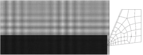
[image:3.595.307.558.310.407.2]The initial geometry of the model is presented in Fig. 1. The workpiece is a rectangular block and the tool moves into it horizontally. The space above the workpiece, in which the chip will form and is initially filled with void, needs to be meshed. This increases the number of elements composing the mesh. In order to reduce it, the height of the model is smaller when the uncut chip thickness, h, is smaller. According to Ducobu et al. [21] ,the elements shape should be a square and their size close to 5 µm in order to avoid influencing the chip formation and cutting forces. Square elements of 5 µm long are therefore used to mesh the workpiece and the space above it (the Eulerian domain). The model is composed of 40,744 nodes for h = 0.1 mm and of 48,780 nodes for h = 0.2 mm.
Fig. 1. Initial geometry of the model for an uncut chip thickness, h, of 0.1 mm; the zone corresponding to the workpiece is in black.
The tool is modelled as an elastic body made of tungsten carbide while the AA2024-T3 workpiece is a thermo-elasto-visco-plastic body with damage properties. The material constitutive model is the well-known Johnson-Cook (JC) model [25] with A, B, C, m and n the material parameters, the reference strain rate, and and the melting and the room temperatures, respectively:
(1)
Table 1 presents the parameters values adopted in this study.
Damage properties are included in the description of AA2024-T3 behaviour. In this model, it is important to stress that material failure is not used as a chip separation criterion, as in [9, 18, 26] for example, because it is not needed thanks to the Eulerian formulation (chip separation occurs therefore thanks to material flow around the tool tip). Material damage and failure are taken into account to accurately model the material behaviour in two stages: the onset of damage (or damage initiation criterion) and the propagation of damage leading to failure (or damage propagation and failure criterion).
The strain value at the onset of damage, f, is calibrated by
(2)
[image:4.595.40.289.191.605.2]with : the stress triaxiality.
Table 1. Materials physical and mechanical properties, cutting conditions and tool geometry [18, 20, 28, 29].
JC constitutive model A (MPa) 350
B (MPa) 675
C 0.0085
m 1
n 0.57
(s-1) 0.0013
(K) 293
(K) 798
Stress intensity factor, mode I KIC (MPa m1/2) 37
Young’s modulus, E (GPa) AA2024-T3 73
Carbide 800
Poisson’s ratio, AA2024-T3 0.33
Carbide 0.2
Density, (kg/m³) AA2024-T3 2,700
Carbide 15,000
Conductivity, k (W/mK) AA2024-T3 120
Carbide 46
Specific heat, cp (J/kgK) AA2024-T3 875
Carbide 203
Friction coefficient 0.2
Limiting shear stress (MPa) 20
Friction energy to heat (%) 100
Heat partition to workpiece (%) 50
Inelastic heat fraction 0.9
Cutting speed, vc (m/min) 30; 60; 120
Uncut chip thickness, h (mm) 0.1; 0.2
Rake angle, (°) 23
Clearance angle, (°) 7
Cutting edge radius, r (µm) 10
Once damage is initiated in the material, it will propagate which induces a softening of the material. The propagation of damage is implemented in the same way as in a Lagrangian model using this 2 steps approach, introduced by Mabrouki et al. [18]. It consists in a linear softening of the material to reach failure at the equivalent plastic displacement value, uf,pl,
estimated from the fracture energy, Gf, and the yield stress, y:
(3)
The fracture energy is computed thanks to the stress intensity factor in mode I, KIC:
(4)
The failure criterion does not depend on the cutting parameters. It is assumed that it has a single value, like the fracture energy. The damage initiation criterion depends on the cutting conditions as they will influence the stress triaxiality.
This material behaviour description has not been adopted previously in the simulation of the cutting process, no matter the formulation (Lagrangian, Eulerian or one of their combinations).
Few data are available in the literature on friction for the couple of materials considered. In accordance with the work of Subbiah and Melkote [29], friction between the tool and the workpiece is modelled with an extended Coulomb friction model. Under a limiting shear stress value of 20 MPa, sliding occurs and the shear stress is related to the normal contact pressure by a friction coefficient of 0.2. Above the limiting shear stress value, the shear stress is equal to this limiting shear stress value and sticking occurs. As usual in finite element modelling of orthogonal cutting, all the friction energy is assumed to be converted into heat and this heat is equally allocated to the tool and the workpiece. In addition, the efficiency of the conversion of plastic dissipation energy to heat is 90%.
All the parameters used in this study come from experiments or from the literature. They will not be modified (“tuned”) to improve the results. This is performed with the objective to develop a predictive model from available inputs without any artificial tuning that would lead to increasing the model performance but only for the limited (set of) cutting condition(s) considered.
4.Results
[image:4.595.317.543.557.721.2]Figure 2, below, shows the measured cutting and feed forces at the selected depth of cuts and cutting speeds where the forces are reduced by an increase in the cutting speed and a reduction of the initial depth of cut. All the obtained chips were continuous.
F. Ducobu et al. / Procedia CIRP 82 (2019) 142–147 145
Fig. 3. Numerical chips, temperature contours (in K), at a length of cut of 0.45 mm for h = 0.1 mm and (a) vc = 120 m/min, (b) vc = 60 m/min, (c) vc = 30 m/min,
at a length of cut of 0.9 mm for h = 0.2 mm and (d) vc = 120 m/min, (e) vc = 60 m/min, (f) vc = 30 m/min.
The numerical chips from the 6 models are provided in Fig. 3. All the chips are continuous as it was expected from the experiments.
The high temperature area is in the secondary shear zone as expected, demonstrating that the chip formation phenomena are qualitatively well captured by the model.
[image:5.595.322.549.378.713.2]In addition, temperature at the tool – chip interface increases with the cutting speed. This is as well an effect that was expected. It contributes to show that the physics of the chip formation is numerically sound. Figure 4 shows the damage variable for a set of cutting conditions; the results are similar for the other cutting conditions. High damage values are only found on the machined surface and on the newly created surface of the chip. This is in accordance with the production of a continuous chip and the stress and strain state of the material in the chip is constant through its length (once regime is reached after the tool entrance in the workpiece).
Fig. 4. Damage variable contours (a value of 1 means a failed material) for vc = 120 m/min and h = 0.1 mm at a length of cut of 0.45 mm.
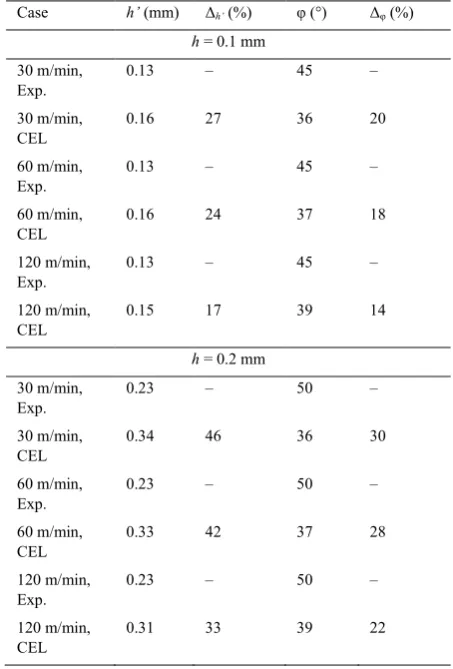
Table 2 compares the numerical chips thicknesses and primary shear angles with the experimental values. The numerical chips are thicker than the experimental ones, with a difference of 22% in average for h = 0.1 mm and of 40% in average for h = 0.2 mm. Experimentally as well as numerically, the cutting speed does not influence much the chip thickness. A slight increase in the shear angle value with the uncut chip thickness is experimentally observed. This
increase is not observed numerically but the shear angle value slightly increases with the cutting speed for both values of the uncut chip thickness.
Table 2. Summary of the results for the chip morphology (h’: chip thickness, : primary shear angle and x: difference with the experimental values).
Case h’ (mm) h’ (%) (°) (%)
h = 0.1 mm
30 m/min, Exp.
0.13 – 45 –
30 m/min, CEL
0.16 27 36 20
60 m/min, Exp.
0.13 – 45 –
60 m/min, CEL
0.16 24 37 18
120 m/min, Exp.
0.13 – 45 –
120 m/min, CEL
0.15 17 39 14
h = 0.2 mm
30 m/min, Exp.
0.23 – 50 –
30 m/min, CEL
0.34 46 36 30
60 m/min, Exp.
0.23 – 50 –
60 m/min, CEL
0.33 42 37 28
120 m/min, Exp.
0.23 – 50 –
120 m/min, CEL
0.31 33 39 22
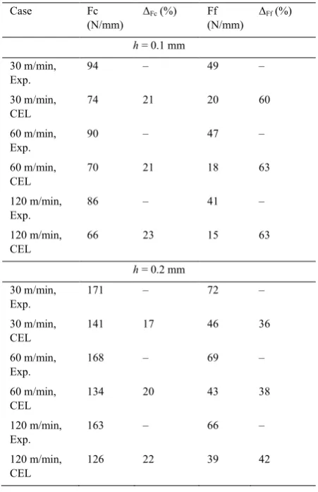
[image:5.595.44.274.524.639.2]underestimated by the model. As usually noticed in finite element modelling of the cutting process, the cutting force is better estimated than the feed force [30, 31].
[image:6.595.46.272.356.705.2]In accordance with the experimental results, the forces increase with the uncut chip thickness and the reduction of the cutting speed. The numerical model correctly captures the experimental trends when the uncut chip thickness and the cutting speed are changed: doubling the cutting speed leads to a small change in the cutting force, while doubling the uncut chip thickness nearly doubles the cutting force. The predictive goal of the model, its main objective when developed is therefore reached. For the cutting force, the difference is in the range of 21% with an increasing tendency with the cutting speed and when the uncut chip thickness decreases. The tendencies are the same for the feed force but, this time, the difference is not in the same range when the uncut chip thickness varies: it is of 62% in average for h = 0.1 mm and of 38% in average for h = 0.2 mm. The closest numerical forces results are therefore obtained at the lowest cutting speed value and the largest uncut chip thickness value, vc = 30 m/min and h = 0.2 mm.
Table 3. Summary of the results for the forces (Fc: cutting force, Ff: feed force and x: difference with the experimental values).
Case Fc
(N/mm)
Fc (%) Ff
(N/mm)
Ff (%)
h = 0.1 mm
30 m/min, Exp.
94 – 49 –
30 m/min, CEL
74 21 20 60
60 m/min, Exp.
90 – 47 –
60 m/min, CEL
70 21 18 63
120 m/min, Exp.
86 – 41 –
120 m/min, CEL
66 23 15 63
h = 0.2 mm
30 m/min, Exp.
171 – 72 –
30 m/min, CEL
141 17 46 36
60 m/min, Exp.
168 – 69 –
60 m/min, CEL
134 20 43 38
120 m/min, Exp.
163 – 66 –
120 m/min, CEL
126 22 39 42
The cutting process is therefore qualitatively correctly modelled and the variations with the cutting conditions are well captured; the influence of the uncut chip thickness is significant, while the influence of the cutting speed on the cutting forces is small.
5.Conclusions and future works
A 2D plane strain orthogonal cutting CEL model with Johnson-Cook material behaviour and Bao-Wierzbicki model to describe the behaviour of the machined material, AA2024-T3, has been introduced. The adopted parameters directly came from the experiments or from the literature. The model predicted qualitatively well the experimental results. The quantitative comparison showed differences with the experimental reference of 20% in average for the cutting force and in average of 40-60% for the feed force. It is of 31% in average for the chip thickness. Better results should be achieved with a tuning of the material parameters. Such a tuning is however not the point of this study as we aim at directly applying known parameters to the numerical CEL model in order to develop a predictive model instead of a model dedicated to the reproduction of a determined set of cutting conditions. Improvement of the friction modelling and influence of the hourglass control method are other ways to reduce the difference between experimental and numerical results that should be explored in the future.
The combination of the damage model and the failure criterion adopted has not been used so far for the modelling of orthogonal cutting, furthermore with the CEL formulation. This study showed that it is able to give reliable results when a predictive model is searched for.
Future works include the comparison of the current results
with a more “conventional” formulation, such as the
Lagrangian formulation, and the extension of the study to a broader range of cutting conditions including the formation of chips that are not continuous (segmented for example).
Acknowledgements
The experimental study was financially supported by research grant #103783 from Innovate UK.
Computational resources for Abaqus have been provided by the supercomputing facilities of the University of Mons (Dragon1/UMONS) and the Consortium des Équipements de Calcul Intensif (CÉCI), funded by the Fonds de la Recherche Scientifique de Belgique (F.R.S.-FNRS) under Grant No. 2.5020.11. François Ducobu gratefully acknowledges Sébastien Kozlowskyj, System Manager of Dragon1, for his help and support to run Abaqus on the cluster, as well as Dr. Martin Bäker (TU Braunschweig) for his Abaqus plugin
“SpectrumBaker” dedicated to results visualization.
References
1. Merchant, M.E., Mechanics of the Metal Cutting Process. I. Orthogonal Cutting and a Type 2 Chip. Journal of Applied Physics, 1945. 16(5): p. 267.
2. Arrazola, P., T. Özel, D. Umbrello, M. Davies,I. Jawahir, Recent Advances in Modelling of Metal Machining Processes. CIRP Annals, 2013. 62(2): p. 695.
3. Marusich, T.D.,M. Oritz, Modeling and Simulation of High-Speed Machining. International Journal for Numerical Methods in Engineering, 1995. 38(21): p. 3675.
4. Sekhon, G.S.,J.L. Chenot, Numerical Simulation of Continuous Chip Formation During Non-Steady Orthogonal Cutting. Engineering Computation, 1993. 10: p. 31.
F. Ducobu et al. / Procedia CIRP 82 (2019) 142–147 147
349.
6. Carroll III, J.T.,J.S. Strenkowski, Finite Element Models of Orthogonal Cutting with Application to Single Point Diamond Turning. International Journal of Mechanical Sciences, 1988. 30(12): p. 899.
7. Movahhedy, M.R., M.S. Gadala,Y. Altintas, Simulation of Orthogonal Metal Cutting Process Using an Arbitrary Lagrangian- Eulerian Finite-Element-Method. Journal of Materials Processing Technology, 2000. 103: p. 267.
8. Movahhedy, M.R., M.S. Gadala,Y. Altintas, Simulation of Chip Formation in Orthogonal Metal Cutting Process: An Ale Finite Element Approach. Machining Science and Technology, 2000. 4(1): p. 15.
9. Ducobu, F., E. Rivière-Lorphèvre,E. Filippi, Numerical Contribution to the Comprehension of Saw-Toothed Ti6al4v Chip Formation in Orthogonal Cutting. International Journal of Mechanical Sciences, 2014. 81: p. 77.
10. Galeati, G., G. Gambolati,S. Neuman, Coupled and Partially Coupled Eulerian Lagrangian Model of Freshwater Seawater Mixing. Water Resources Research, 1992. 28(1): p. 149.
11. Shin, Y.S.,J.E. Chisum, Modeling and Simulation of Underwater Shock Problems Using a Coupled Lagrangian—Eulerian Analysis Approach. Shock and Vibration, 1997. 4(1): p. 1.
12. Al-Badour, F., N. Merah, A. Shuaib,A. Bazoune, Coupled Eulerian Lagrangian Finite Element Modeling of Friction Stir Welding Processes. Journal of Materials Processing Technology, 2013. 213(8): p. 1433.
13. Qiu, G., S. Henke,J. Grabe, Application of a Coupled Eulerian–
Lagrangian Approach on Geomechanical Problems Involving Large Deformations. Computers and Geotechnics, 2011. 38(1): p. 30. 14. Rice, J.R.,D.M. Tracey, On the Ductile Enlargement of Voids in
Triaxial Stress Fields. Journal of Mechanical Physics Solids, 1969. 17: p. 201.
15. Hashemi, J., A.A. Tseng,P.C. Chou, Finite Element Modeling of Segmental Chip Formation in High-Speed Orthogonal Cutting. Journal of Materials Engineering and Performance, 1994. 3(5): p. 712.
16. Rhim, S.H.,S.I. Oh, Prediction of Serrated Chip Formation in Metal Cutting Process with New Flow Stress Model for Aisi 1045 Steel. Journal of Materials Processing Technology, 2006. 171(3): p. 417. 17. Ceretti, E., P. Fallbohmer, W.T. Wu,T. Altan, Application of 2d Fem
to Chip Formation in Orthogonal Cutting. Journal of Materials Processing Technology, 1996. 59(1-2): p. 169.
18. Mabrouki, T., F. Giradin, M. Asad,J.F. Rigal, Numerical and Experimental Study of Dry Cutting for an Aeronautic Aluminium Alloy (Aa2024-T351). International Journal of Machine Tools and Manufacture, 2008. 48(11): p. 1187.
19. Bao, Y.,T. Wierzbicki, A Comparative Study on Various Ductile
Crack Formation Criteria. Journal of Engineering Materials and Technology, 2004. 126(3): p. 314.
20. Ghadbeigi, H., Metal Cutting Mechanics: Investigation and Simulation of Deformation and Damage Mechanisms, in Department of mechanical engineering. 2010, The University of Sheffield: Sheffield.
21. Ducobu, F., E. Riviere-Lorphervre,E. Fillippi, Mesh Influence in Orthogonal Cutting Modelling with the Coupled Eulerian-Lagrangian (Cel) Method. European Journal of Mechanics-A/Solids, 2017. 65: p. 324.
22. Ducobu, F., P.-J. Arrazola, E. Rivière-Lorphèvre, G.O. de Zarate, A. Madariaga,E. Filippi, The Cel Method as an Alternative to the Current Modelling Approaches for Ti6al4v Orthogonal Cutting Simulation. Procedia CIRP, 2017. 58: p. 245.
23. Ducobu, F., E. Rivière-Lorphèvre,E. Filippi, Finite Element Modelling of 3d Orthogonal Cutting Experimental Tests with the Coupled Eulerian-Lagrangian (Cel) Formulation. Finite Elements in Analysis and Design, 2017. 134: p. 27.
24. Ducobu, F., E. Riviere-Lorphervre,E. Filippi, Application of the Coupled Eulerian-Lagrangian (Cel) Method to the Modeling of Orthogonal Cutting. European Journal of Mechanics A/Solids, 2016. 59: p. 58.
25. Johnson, G.K.,W.H. Cook. A Constitutive Model and Data for Metals Subjected to Large Strains Large Strain Rates and High Temperatures. in The 7th International Symposium on Ballistics. 1983. Hague, Netherlands.
26. Zhang, Y., T. Mabrouki, D. Nelias,Y. Gong, Chip Formation in Orthogonal Cutting Considering Interface Limiting Shear Stress and Damage Evolution Based on Fracture Energy Approach. Finite Elements in Analysis and Design, 2011. 47(7): p. 850.
27. Bao, Y.,T. Wierzbicki, On Fracture Locus in the Equivalent Strain and Stress Triaxiality Space. International Journal of Mechanical Sciences, 2004. 46(1): p. 81.
28. Ghadbeigi, H., S.R. Bradbury, C. Pinna,J.R. Yates, On the Modelling of Chip Formation in Orthogonal Cutting: Damage Mechanics Approach, in 12th CIRP Conference on Modelling of Machining Operations, P.J. Arrazola and I.S. Jawahir, Editors. 2009: Donostia-San Sebastian, Spain.
29. Subbiah, S.,S.N. Melkote, Effect of Finite Edge Radius on Ductile Fracture Ahead of the Cutting Tool Edge in Micro-Cutting of Al2024-T3. Materials Science and Engineering: A, 2008. 474(1-2): p. 283. 30. Sima, M.,T. Özel, Modified Material Constitutive Models for Serrated
Chip Formation Simulations and Experimental Validation in Machining of Titanium Alloy Ti–6al–4v. International Journal of Machine Tools and Manufacture, 2010. 50(11): p. 943.
![Table 1. Materials physical and mechanical properties, cutting conditions and tool geometry [18, 20, 28, 29]](https://thumb-us.123doks.com/thumbv2/123dok_us/1824293.138186/4.595.40.289.191.605/table-materials-physical-mechanical-properties-cutting-conditions-geometry.webp)