CFD SIMULATION OF SHELL AND TUBE TYPE HEAT EXCHANGER: EFFECT OF FLOW CONDITION
WILFRED TANG KAH JUNG
This report is submitted
in fulfillment of the requirement for the degree of Bachelor of Mechanical Engineering (Thermal-Fluid)
Faculty of Mechanical Engineering
UNIVERSITI TEKNIKAL MALAYSIA MELAKA
ii
DECLARATION
I declare that this project report entitled “CFD Simulation of Shell and Tube Type Heat Exchanger: The Effect of Flow Condition” is the result of my own work except as cited in the references.
iii APPROVAL
I hereby declare that I have read this project report and in my opinion this report is sufficient in terms of scope and quality for the award of the degree of Bachelor of Mechanical Engineering (Thermal-Fluid).
iv
DEDICATION
v ABSTRACT
vi ABSTRAK
vii
ACKNOWLEDGEMENT
First, I would like to express my gratitude to my supervisor, Dr. Fatimah Al-Zahrah Mohd Sa’at, who has guided me to successfully complete my final year project with her knowledges and ideas. I also would like to thank Dr. Ernie Binti Mat Tokit and Dr. Nazri bin Md Daud for evaluating my final year project. The ideas and suggestion given were important for me to complete this project.
Besides, I also want to thank the Faculty of Mechanical Enginnering(FKM), Universiti Teknikal Malaysia Melaka (UTeM) for allowing me to use the equipment and tools which helped me to complete this project successfully.
viii
TABLE OF CONTENTS
CHAPTER CONTENT PAGE
DECLARATION ii
APPROVAL iii
DEDICATION iv
ABSTRACT v
ABSTRACK vi
ACKNOWLEDGEMENT vii
TABLE OF CONTENTS viii
LIST OF TABLES xi
LIST OF FIGURES xii
LIST OF ABBREVIATIONS xv
LIST OF SYMBOLS xvi
CHAPTER 1 INTRODUCTION
1.1 Background 1
1.2 Problem Statement 2
1.3 Scope 3
1.4 Objective 4
CHAPTER 2 LITERATURE REVIEW 2.1 Heat Exchanger
2.1.1 Counter Flow Heat Exchanger 2.1.2 Parallel Flow Heat Exchanger 2.1.3 Cross Flow Heat Exchanger 2.1.4 Hybrid Heat Exchanger
5 5 7 8 9 2.2 Shell and Tube Heat Exchanger 10
ix
2.3.1 Viscous Versus Inviscid Regions of Flow 2.3.2 Internal versus External Flow
2.3.3 Compressible versus Incompressible Flow 2.3.4 Laminar versus Turbulent Flow
2.3.5 Natural versus Forced Flow 2.3.6 Steady versus Unsteady Flow
2.3.7 One-, Two-, and Three-Dimensional Flows
14 15 15 16 17 17 18 2.4 Flow Characteristics in SNTHE 19 2.5 CFD in Shell and Tube Heat Exchanger 21
CHAPTER 3 METHODOLOGY
3.1 Introduction 25
3.2 Geometry 27
3.3 Mesh Generation 28
3.4 Solver Setup
3.4.1 Assumption
29 29 3.4.2 Boundary Condition
3.4.3 Solver
29 30
CHAPTER 4 RESULT AND DISCUSSION
4.1 Overview 31
4.2 Grid Independency Test and Validation 31 4.3 Ammonia
4.3.1 Ammonia Flow Contour
4.3.2 Ammonia Temperature Contour 4.3.3 Ammonia Velocity Distribution 4.3.4 Ammonia Temperature Distribution
34 34 35 37 38 4.4 Isobutane (R600a)
4.4.1 R600a Flow Contour
4.4.2 R600a Temperature Contour 4.4.3 R600a Velocity Distribution 4.4.4 R600a Temperature Distribution
39 40 41 43 44
x
4.5.1 Carbon Dioxide Flow Contour
4.5.2 Carbon Dioxide Temperature Contour 4.5.3 Carbon Dioxide Velocity Distribution 4.5.4 Carbon Dioxide Temperature Distribution
45 46 47 48
4.6 Analysis and Discussion 48
5.0 Conclusion 53
REFERENCE 55
xi
LIST OF TABLES
FIGURE TITLE PAGE
4.1 Fluid Properties of Ammonia, R600a and Carbon Dioxide 31
4.2 Grid Independency Test Result 32
4.3 Percentage Difference 33
xii
LIST OF FIGURES
FIGURE TITLE PAGE
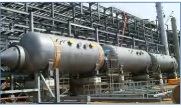
1.1 Shell and Tube Heat Exchanger in food industry 1 1.2 Shell and Tube Heat Exchanger in petrochemical industry 1
2.1(a) Counter Flow 6
2.1(b) Temperature profile of cross flow 6
2.2 Plate Heat Exchanger 7
2.3(a) Parallel Flow 7
2.3(b) Temperature Profile 7
2.4 Cross Flow 8
2.5 Different flow configuration in cross-flow heat exchanger 8
2.6 Cross Flow 9
2.7 Helical coil tube 10
2.8 Schematic of one-shell pass and one-tube pass SNHTE 11
2.9 Fixed Tube Sheet 12
2.10 Floating Heat Exchanger 12
2.11 Heat exchanger with kettle and U-tube 13 2.12 Illustration of Viscous and Inviscid Flows 14
xiii
2.14 Meshing at the tubes 24
3.1 Flow Chart 26
3.2 Geometry of un-baffle SNTHE 27
3.3 Mesh with Tetrahedron and Inflation 28
3.4 Wall Selection 29
4.1 Ammonia Flow Contour at Inlet of theShell 35 4.2 Ammonia Flow Contour at Central Plane 35 4.3(a) Temperature Contours of Ammonia at Central Plane 36 4.3(b) Temperature Contours of Ammonia at Inlet of the Shell 36 4.3(c) Temperature Contours of Ammonia at Outlet Plane 37
4.4(a) Variation of Ammonia Axial Velocity with Dimensionless
Radial Distance 38
4.4(b) Axial Distance 38
4.5(a) Variation of Ammonia Temperature with Dimensionless Axial Distance
39
4.5(b) Radial Distance 39
4.6(a) R600a Flow Contour at Inlet of the Shell 40 4.6(b) R600a Flow Contour at Central Plane 41 4.7(a) Temperature Contours of R600a at Central Plane 42
4.7(b) Temperature Contours of R600a at Inlet of the Shell 42 4.7(c) Temperature Contours of R600a at Outlet Plane 42 4.8(a) Variation of R600a Axial Velocity with Dimensionless
Radial Distance 43
xiv
4.9(a) Variation of R600a Temperature with Dimensionless Axial Distance
44
4.9(b) Radial Distance 44
4.10 CO2 Flow Contour at Inlet of the Shell 45 4.11 CO2 Flow Contour at Central Plane 46 4.12(a) Temperature Contours of CO2 at Central Plane 46 4.12(b) Temperature Contours of CO2 at Inlet of the Shell 47 4.12(c) Temperature Contours of CO2 at Outlet Plane 47 4.13(a) Variation of CO2 Axial Velocity with Dimensionless Radial
Distance 47
4.13(b) Axial Distance 47
4.14(a) Variation of CO2 Temperature with Dimensionless Axial Distance
48
4.14(b) Radial Distance 48
xv
LIST OF ABBEREVATIONS
SNTHE Shell and Tube Heat Exchanger CFD Computational Fluid Dynamics HE Heat Exchanger
LMTD Log Mean Temperature Difference ODS Operating Deflection Shape
AHU Air Handling Unit R600a Isobutane
xvi
LIST OF SYMBOLS
D = inner diameter of the tube
V = average velocity of the fluid
𝜌 = density of the fluid
µ = dynamic viscosity
𝑚̇ = mass flow rate
𝑣 = kinematic viscosity
Re =Reynolds Number
Dh =Hydraulic Diameter
h =Heat Transfer Coefficient
Nu =Nusselt Number
1 CHAPTER 1
INTRODUCTION
1.1 BACKGROUND
[image:17.595.156.453.429.541.2]Shell and Tube Heat Exchangers (SNTHE) are widely used in the industry as they have flexible designs. According to Chunnangad (2006), more than 35-40% heat exchangers are SNTHE. Usually, SNTHE are found in petrochemical and food industries. Their main purpose is to perform heating, cooling, condensation and boiling process. The main reason they are preferred in the industry is because they offer wide range of temperature change, and easy to be maintained.
Figure 1.1: Shell and Tube Heat Exchanger in food industry
[image:17.595.215.395.601.708.2]2
According to Pal (2016), SNTHE are popular in these industries because of its high rate of heat transfer in terms of volume and weight. Not only that, SHTHE can be built easily as it built from ranges tubes sizes with the strength to withstand the fabrication stress, shipping, fields erection stress and operation. Plus, the crucial SHTHE part like gasket, tubes screw can be replaced easily as all these components are easily found in the aftermarket. This makes the SNTHE to be maintained easily and cheaply.
In the industry, SNTHE are important for its ability to handle fluid of different temperature, flow rates, thermal properties and different expansion rates of metals. When mentioning handling fluids, it demotes the involvement of two or more liquids in the heat exchange process of convection and conduction. This is similar to mixing chamber where two different types of liquids with different temperature are mixed to achieve desired temperature. The difference between mixing chamber and SNTHE is that, SNTHE do not mixed the liquids to achieved desired temperature.
According to Aslam (2012), cross flow between tube banks and shell side are important aspects as it represents the ideal process in many important industry processes like flow in filtration, biological system, fibrous media or insulation material.
1.2 PROBLEM STATEMENT
3
SNTHE today are equipped with baffles as the main supporter for the tubes and the baffles also provide certain behaviour of shell-side flow. However, there are some problems encountered by this device. The presence of baffle affects the shell-side flow. The subsequent flow contraction and expansion has caused flow separation at the edge of the baffle causing the pressure to drop significantly.
Besides that, there are issues of ‘dead zones’ at some areas near baffles. The ‘dead zones’ are area near baffles that are not reached by the fluid. The phenomenon could happen at certain condition of fluid flow like low fluid velocity, low mass flow rate, unstable of Reynolds number and poor shell and tube heat exchanger design. This ‘dead zones’ will greatly affect the heat exchange rate between the inner wall and outer wall as the dead zone are the part where the heat is not reach by fluid to carry out the heat exchange process (Wang, 2010).
1.3 SCOPE
1. To use CFD software to stimulate the flow.
2. To study the temperature distribution of three different type of coolants in Shell and Tube Heat Exchanger (SNTHE)
3. To study the flow condition of three different type of coolants in Shell and Tube Heat Exchanger (SNTHE)
4
transfer. The next scope of this study is to study the temperature distribution inside the Shell and Tube Heat Exchanger (SNTHE). Not only that, the flow condition such as velocity vector, velocity penetration are also further studies and identified their effect on the heat exchange process.
1.4 OBJECTIVE
1. To study a functional CFD model of Shell and Tube Heat Exchanger
2. To compare the temperature distribution of three different coolant in Shell and Tube Heat Exchanger.
5 CHAPTER 2
LITERATURE REVIEW
2.1 Heat Exchanger
According to Yong (2015), heat exchangers (HE) are devices that transfers heat between one or more fluids. Fluids are usually separated by the solid wall to prevent the fluid from mixing or contacting each other. HE is very important in the industry as it is widely used in air conditioning, chemical plants, natural-gas processing, sewage treatment, space heating, petrochemical plants, petroleum refineries and power station. One of the conventional HE examples is internal combustion engine where engine coolant flows through radiator coils. At the same time, air passes through coils and cooled the coolant and heats the air. In heat exchanger, there are four basic flow configurations, counter flow heat exchanger, parallel flow heat exchanger, mixed flow heat exchanger and hybrid heat exchanger (Yong et al., 2015).
2.1.1 Counter Flow Heat Exchanger
6
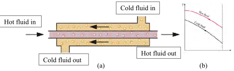
[image:22.595.94.506.65.191.2](a) (b)
Figure 2.1: (a) Counter Flow, (b) temperature profile of cross flow (Cengel and Ghajar, 2015)
According to Zhang (2016), plate heat exchanger is one of the common types of counter flow heat exchanger. Plate heat exchanger is mainly build with plates and frames. The plates are thin and large in surface area and the plates are equally separated. The gaps between the plates are usually small as small fluid flow is required to enhance the heat transfer process.
There are two types of plate heat exchangers, closed loop and open loop. For closed loop plate heat exchanger, the plates are permanently bonded by brazing and welding. Closed looped applications are like refrigeration cycle. Well for open loop plate’s heat exchanger, the plates are mounted and assembled like gasket. Because of these features, it allows the plates to undergo cleaning, inspection or disassembly easily.
The plate heat exchanger will carry out heat transfer by means of conduction and convection. There are two types of plates in the plate heat exchanger. Upward flow plates and downward flow plates. These plates are arranged alternatively and the hot fluid will flow in upward flow plates while the cold will flow in downwards flow plats or vice versa (Zhang et al., 2016).
Hot fluid in
Hot fluid out Cold fluid out
7
Figure 2.2: Plate Heat Exchanger (Cengel and Ghajar, 2015)
2.1.2 Parallel Flow Heat Exchanger
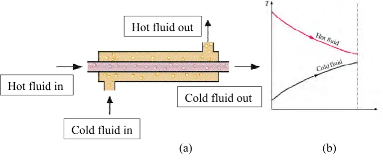
In parallel flow heat exchanger, the fluid flows parallelly in the same direction. Although it is less efficient than counter flow heat exchanger in terms of heat transfer, however, this kind of flow provide a more uniform wall temperature. For parallel flow type of heat exchanger, there is no specific type of heat exchanger as it can be applied for vertical and horizontal flow heat exchanger (Cengel and Ghajar, 2015).
(a) (b)
Figure 2.3: (a) Parallel Flow, (b) Temperature Profile (Cengel et al., 2015) Cold fluid out
Hot fluid out
Hot fluid in
[image:23.595.85.470.529.691.2]8 2.1.3 Cross Flow Heat Exchanger
[image:24.595.178.456.215.380.2]In cross flow heat exchanger, Brogan (2011) stated that the fluid flows at 90 degrees. For this kind flow, its efficiency is lower than counter flow but higher than parallel flows. According to Cengel and Ghajar (2015), cross flow heat exchanger can be classified as mixed and unmixed flow.
Figure 2.4: Cross Flow (Brogan, 2011)
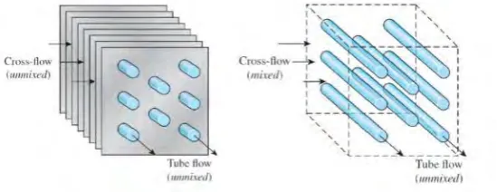
Based on the Figure 2.5 (a), it can be observed that the flow is unmixed as the fluids are forced to flow through plate fins interfin spacing in the transverse direction. Cross-flow in (b) is categorized as mixed as the fluid is free to move in transverse direction without being confined to the plate as the model in Figure 2.5 (a).
(a) Both fluids unmixed (b) one fluid unmixed, one fluid mixed
Figure 2.5: Different flow configuration in cross-flow heat exchanger (Cengel et al., 2015) Cold fluid out
Cold fluid in
[image:24.595.180.455.537.643.2]