WEEKEND
CR
ASH
COURSE
WEEKEND
CR
ASH
COURSE
™UML
THOMAS A.
PENDER
UML modeling tools,
self-assessment
software, and
more on CD-ROM
30 Sessions
That Will Have
You Working
with UML in
Only 15 Hours
UM
L
HOUR
15
15
he big day is Monday. The day you get to show off what you know about the Unified Modeling Language. The problem is, you’re not really up to speed. Maybe it’s been a while since you worked with UML. Or maybe you just like a challenge. In any event, we’ve got a solution for you — UML Weekend Crash Course. Open the book Friday evening and on Sunday afternoon, after completing 30 fast, focused sessions, you’ll be able to dive right in and start modeling business processes, objects, data, XML, and more. It’s as simple as that.
in a Weekend!
in a Weekend!
CD-ROM INCLUDES:
• System Architect trial version
• Describe Enterprise trial version
• Supplemental illustrations and cheat sheets
• Assessment software
• Fully searchable e-version of the book
• Complete UML specification
System Requirements: PC with Pentium 200 or higher, running Windows NT or 2000, 64 MB RAM, CD-ROM drive. See the “What’s on the CD-ROM” appendix for details and complete system requirements.
Category: Programming/ Data Modeling & Design
WEEKEND CRASH COURSE
WEEKEND CRASH COURSE
T
™
ISBN 0-7645-4910-3
,!7IA7G4-fejbag!:p;M;t;t;T
The Curriculum
FRIDAY
Evening: 4 Sessions, 2 Hours • What Is the UML? • UML and Development
Methodologies • How to Approach the
UML
• Defining Requirements for the Case Study
SATURDAY
Morning: 6 Sessions, 3 Hours • Understanding the Use
Case Model
• Building the Use Case Diagram
• Building the Use Case Narrative
• Identifying the Use Case Scenarios
• Modeling the Static View: The Class Diagram • The Class Diagram:
Associations
SATURDAY, continued
Afternoon: 6 Sessions, 3 Hours • The Class Diagram:
Aggre-gation and Generalization • Applying the Class
Diagram to the Case Study • Modeling the Static View:
The Object Diagram • Modeling the Functional
View: The Activity Diagram • Applying the Activity
Diagram to the Case Study • Modeling the Dynamic
View: The Sequence Diagram
Evening: 4 Sessions, 2 Hours • Applying the Sequence
Diagram to the Case Study • Modeling the Dynamic
View: The Collaboration Diagram
• Applying the Collaboration Diagram to the Case Study • Modeling the Dynamic
View: The Statechart Diagram
SUNDAY
Morning: 6 Sessions, 3 Hours • Applying the Basic
Statechart to the Case Study
• Modeling the Extended Features of the Statechart • Applying the Extended
Statechart Features to the Case Study
• Modeling the Development Environment
• Modeling the Static View: The Component Diagram • Modeling the Static View:
The Deployment Diagram
Afternoon: 4 Sessions, 2 Hours • Introduction to Web
Development with Java • Analysis and Architectural
Design of a Web Application • Design of a Web
Application • UML Modeling Tools
WEEKEND
CRASH
COURSE
HOURS
*85555-BADCCb
For more information on Wiley Publishing, Inc., go to www.wiley.com/compbooks/UML
UML
Weekend Crash Course
™
Thomas A. Pender
Wiley Publishing, Inc.
909 Third Avenue New York, NY 10022
www.wiley.com
Copyright © 2002 by Wiley Publishing, Inc., Indianapolis, Indiana LOC: 2002103278
ISBN: 0-7645-4910-3
Manufactured in the United States of America 10 9 8 7 6 5 4 3 2 1
1B/SQ//QW/QS/IN
Published by Wiley Publishing, Inc., Indianapolis, Indiana Published simultaneously in Canada
No part of this publication may be reproduced, stored in a retrieval system or transmitted in any form or by any means, electronic, mechanical, photocopying, recording, scanning or otherwise, except as permitted under Sections 107 or 108 of the 1976 United States Copyright Act, without either the prior written permission of the Publisher, or authorization through payment of the appropriate per-copy fee to the Copyright Clearance Center, 222 Rosewood Drive, Danvers, MA 01923, (978) 750-8400, fax (978) 750-4744. Requests to the Publisher for permission should be addressed to the Legal Department, Wiley Publishing, Inc., 10475 Crosspoint Blvd., Indianapolis, IN 46256, (317) 572-3447, fax (317) 572-4447, E-Mail: [email protected].
Limit of Liability/Disclaimer of Warranty:While the publisher and author have used their best efforts in preparing this book, they make no representations or warranties with respect to the accuracy or completeness of the contents of this book and specifically disclaim any implied warranties of merchantability or fitness for a particular purpose. No warranty may be created or extended by sales representatives or written sales materials. The advice and strategies con-tained herein may not be suitable for your situation. You should consult with a professional where appropriate. Neither the publisher nor author shall be liable for any loss of profit or any other commercial damages, including but not lim-ited to special, incidental, consequential, or other damages.
For general information on our other products and services or to obtain technical support, please contact our Customer Care Department within the U.S. at 800-762-2974, outside the U.S. at 317-572-3993 or fax 317-572-4002.
Wiley also publishes its books in a variety of electronic formats. Some content that appears in print may not be avail-able in electronic books.
Trademarks:Wiley, the Wiley Publishing logo, Weekend Crash Course and related trade dress are trademarks or regis-tered trademarks of Wiley Publishing, Inc., in the United States and other countries, and may not be used without written permission. All other trademarks are the property of their respective owners. Wiley Publishing, Inc., is not associated with any product or vendor mentioned in this book.
About the Author
Credits
Acquisitions Editor
Terri Varveris
Project Editor
Sara Shlaer
Technical Editor
Lou Varveris
Copy Editor
Elizabeth Kuball
Editorial Manager
Mary Beth Wakefield
Vice President and Executive Group Publisher
Richard Swadley
Vice President and Executive Publisher
Bob Ipsen
Vice President and Publisher
Joseph B. Wikert
Editorial Director
Mary Bednarek
Project Coordinator
Nancee Reeves
Graphics and Production Specialists
Beth Brooks Sean Decker Melanie DesJardins Kristin McMullan Heather Pope
Quality Control Technicians
Dave Faust John Greenough Andy Hollandbeck Carl Pierce Dwight Ramsey
Permissions Editor
Carmen Krikorian
Media Development Specialist
Travis Silvers
Proofreading and Indexing
W
elcome to the UML Weekend Crash Course.So why another UML book? The Weekend Crash Course series is designed to give you quick access to the topics you want to learn. You won’t find a ton of reference material in this book. You won’t find a book that assumes you have a specific programming background. Instead, you will find the material you need to get the job done, no matter what your background.You are about to experience the joy of discovering and modeling a complete software system design from start to finish. You will be equipped with tools to work with client and technical professionals alike and to overcome so much of the confusion and frustration common to software projects. You will master one of the most practical and useful tools in current technology, the Unified Modeling Language.
Who Should Read This Book
This crash course is designed to provide you with a set of short lessons that you can grasp quickly — in one weekend. The book is intended for three audience categories:
Programmers who want or need to learn more about design and specifically how the tools of the UML help in design. Perhaps you have seen the modeling tools used on projects and want to know how to use them yourself. This course provides 30 focused sessions on the most practical aspects of the UML modeling tools. You will learn the role of each diagram, the notations to draw them, and how to apply them using a realistic case study.
Team leaders and analysts who need a tool to help communicate what the project is all about. You haven’t written code in a while, but you know what you want the sys-tem to do for your clients. You need a way to express the requirements in a way that all the participants can understand and support throughout the project life cycle. The course sessions break down the diagrams to clearly explain why and how you would use them. I also provide tips on how to make sure that what you’re doing is correct. Business analysts and clients who need to communicate with systems developers.
One of the challenges in projects is finding a common language, a way to communi-cate effectively and consistently. The UML provides a common ground for business and technical professionals. The examples in the course are nontechnical yet very practical for establishing a common language to describe critical business systems.
To get the most out of this book, you should be familiar with software projects and the various participants. I don’t cover project management or much of the technology used in projects. In fact, I assume you know the project-related concepts like code, databases, pro-grams, requirements, business processes, clients, developers, and analysts.
What You Need To Have
The requirements for the course are very basic. You can create all the diagrams with pencil and paper. If you like, you can download any one of the modeling tools mentioned in the book. Nearly all vendors provide an evaluation copy for 15 to 30 days, more than enough time to complete the course and try out the tool. For a list of vendor sites see Session 30. I’ll offer two cautions regarding the use of tools: First, there are a few free tools out there, but most of them are not complete and might get in the way of your work. Second, if you are struggling with the tool, go back to paper until you finish the course. Focus on learning the concepts, then work on using a tool. The concepts are more important than the
mechanics of a particular tool.
What Results Can You Expect?
How realistic is it to try to learn the UML in one weekend? The UML is like many things you learn. Grasping the basics is easy, but it can take years to master the application. The UML defines ten diagrams. Five of those get used a lot; the other five are more specialized and are used less frequently. All of the concepts represented in the diagrams should already be familiar, concepts such as clients, business processes, and messages. The toughest part is learning the terminology. That is why the course focuses on giving you definitions and lots of examples.
There is more to the UML than I could possibly cover in 15 hours. But I can give you a solid understanding of the core concepts that will support 80 percent of your work. You will know the purpose of each diagram, how the diagrams work together, the entire notation to construct each diagram, and even ways to test your work. After you work through the examples and the case study, you should be able to immediately start applying your new understanding at work with confidence.
Weekend Crash Course Layout and Features
This book follows the Weekend Crash Course layout and includes the standard features of the series so that you can be assured of mastering the UML within a solid weekend. You should take breaks throughout. I’ve arranged things so that the 30 sessions last approxi-mately 30 minutes each. The sessions are grouped within parts that take two or three hours to complete. At the end of each session, you’ll find “Quiz Yourself” questions, and at the end of each part, you’ll find part review questions. These questions let you test your knowl-edge and practice your newfound skills. (The answers to the part review questions are in Appendix A.) Between sessions, take a break, grab a snack, and refill that beverage glass, before plunging into the next session!
Part I: Friday Evening
In this part, I provide the background of the UML and how you can approach it to get the most out of it. I cover a brief history of the UML and what exactly the UML defines. Next, I briefly cover some sample methodologies to explain the context in which you will use the UML. I also cover an overview of the diagrams supported by the UML and the fundamental object-oriented concepts used throughout the development of those diagrams.
When the background is complete, you will dive into the Case Study to gather requirements.
Part II: Saturday Morning
This part covers the application of the Use Case Model, from the diagram through narratives and scenarios to fully document user requirements. You will learn to identify and define Use Cases in terms that can be verified by your clients. You will explain the requirements of each Use Case so that they form the foundation for testing throughout the project. Then, based on the requirements, you will begin the construction of the Class diagram, including classes and associations.
Part III: Saturday Afternoon
In the afternoon session, you will learn the rest of the Class diagram notation and apply it to the case study. You will refine the Class diagram by applying aggregation, composition, and inheritance. You will then test the Class diagram using the Object diagram, applying test cases to validate your Class diagram notation. You will also learn to use the Activity diagram to model logic, such as business processes and complex system behaviors. Then you start modeling the interactions between objects using the Sequence diagram by bringing together the test cases and the resources defined in your Class diagram.
Part IV: Saturday Evening
You will continue your application of the Sequence diagram. Then you will learn another, complementary tool, the Collaboration diagram, to model object interactions. You will learn the unique properties of these diagrams and how they can work together to reveal holes in your design. For those objects that are constantly changing, you will learn the Statechart diagram so that you can fully understand and document their behavior over time.
Part V: Sunday Morning
The application of the Statechart will continue into Sunday Morning with lots of practical examples. By this time you will have seen a lot of diagrams. You will learn how to organize your work using Package diagrams. Then, when the design is reaching the point where you need to build the system, you will learn how to model the physical implementation using the Component and Deployment diagrams.
Part VI: Sunday Afternoon
Features
First, as you go through each session, look for the following time status icons that let you know how much progress you’ve made throughout the session:
The book also contains other icons that highlight special points of interest:
This flag is to clue you in to an important piece of information that you should file away in your head for later.
This gives you helpful advice on the best ways to do things, or a tricky technique that can make your UML modeling go smoother.
Never fail to check these items out because they provide warnings that you should consider.
This states where in the other sessions related material can be found.
Accompanying CD-ROM
This Weekend Crash Course includes a CD-ROM. It contains trial software, a skills assessment test, a copy of the UML standard, and some supplemental materials I think you will find it useful. For a more complete description of each item on the CD-ROM, see Appendix B.
Reach Out
The publisher and I want your feedback. Please let us know of any mistakes in the book of if a topic is covered particularly well. You can send your comments to the publisher at Wiley Publishing, Inc., 909 Third Avenue, New York, NY, 10022 or e-mail them to www.wiley.com. You also can e-mail me directly at [email protected].
You are ready to begin your Weekend Crash Course. Stake out a weekend, stockpile some snacks, cool the beverage of your choice, set your seat in the upright position, fasten your seat belt, and get ready to learn the UML the easy way. Turn the page and start learning.
Cross-Ref Never
Preface...ix
FRIDAY...2
Part I—Friday Evening ...4
Session 1–What Is the UML? ...5
Session 2–UML and Development Methodologies ...13
Session 3–How to Approach the UML ...23
Session 4–Defining Requirements for the Case Study ...35
SATURDAY
...46Part II—Saturday Morning
...48Session 5–Understanding the Use Case Model ...49
Session 6–Building the Use Case Diagram ...61
Session 7–Building the Use Case Narrative ...69
Session 8–Identifying the Use Case Scenarios ...81
Session 9–Modeling the Static View: The Class Diagram ...93
Session 10–The Class Diagram: Associations ...105
Part III—Saturday Afternoon
...116Session 11–The Class Diagram: Aggregation and Generalization ...117
Session 12–Applying the Class Diagram to the Case Study ...129
Session 13–Modeling the Static View: The Object Diagram ...139
Session 14–Modeling the Functional View: The Activity Diagram ...149
Session 15–Applying the Activity Diagram to the Case Study ...157
Session 16–Modeling the Dynamic View: The Sequence Diagram ...167
Part IV—Saturday Evening ...178
Session 17–Applying the Sequence Diagram to the Case Study ...179
Session 18–Modeling the Dynamic View: The Collaboration Diagram ...187
Session 19–Applying the Collaboration Diagram to the Case Study ...193
Session 20–Modeling the Dynamic View: The Statechart Diagram ...203
SUNDAY...214
Part V—Sunday Morning
...216Session 21–Applying the Basic Statechart to the Case Study ...217
Session 22–Modeling the Extended Features of the Statechart ...227
Session 23–Applying the Extended Statechart Features to the Case Study ...237
Session 24–Modeling the Development Environment ...245
Session 25–Modeling the Static View: The Component Diagram ...255
Session 26–Modeling the Static View: The Deployment Diagram ...263
Part VI—Sunday Afternoon
...276Session 27–Introduction to Web Development with Java ...277
Session 28–Analysis and Architectural Design of a Web Application ...287
Session 29–Design of a Web Application ...297
Session 30–UML Modeling Tools ...307
Appendix A–Answers to Part Reviews ...317
Appendix B–What’s on the CD-ROM?...329
Glossary...333
Index...345
Preface...ix
FRIDAY...2
Part I—Friday Evening ...4
Session
1–What Is the UML? ...5Establishing Standards ...5
Some History behind the UML ...6
What is and is not included in the UML Specification ...6
The UML metamodel ...6
The organization of the metamodel ...7
UML Extension Mechanisms ...8
Ten Diagrams ...9
The Continuing Refinement and Expansion of the UML ...10
Session 2–UML and Development Methodologies ...13
Some Current Methodologies ...13
The Rational Unified Process ...14
Strengths of the RUP ...15
Weaknesses of the RUP ...16
Shlaer-Mellor Method ...16
Strengths of Shlaer-Mellor ...17
Weaknesses of Shlaer-Mellor ...17
CRC ...18
Strengths of CRC ...19
Weaknesses of CRC ...19
Extreme Programming ...20
Strengths of XP ...20
Weaknesses of XP ...20
Resources ...21
Session 3–How to Approach the UML ...23
Views ...23
Functional View ...24
Static View ...25
Dynamic View ...26
Three views ...27
Object-Oriented Principles ...28
Abstraction ...28
What an object knows ...29
Information ...29
Behavior ...30
Encapsulation ...30
To use the object ...30
To make the object work properly ...31
Giving an object purpose ...32
Encapsulation summary ...32
Session 4–Defining Requirements for the Case Study ...35
The Case Study Problem Statement ...35
Receiving ...36
Stocking ...36
Order fulfillment ...36
Shipping ...36
Types of Requirements ...36
Business process ...37
Constraints ...38
Rules ...38
Performance ...39
An Inventory Control System ...40
Identifying requirements ...40
Users ...40
Resources ...41
Functionality ...42
Avoiding early pitfalls ...42
Pitfall #1: Making assumptions ...43
Pitfall #2: Replicating existing implementations ...43
Pitfall #3: Mistaking preferences for requirements ...43
SATURDAY
...46Part II—Saturday Morning
...48Session 5–Understanding the Use Case Model ...49
The Purpose of the Use Case Model ...50
The Resources of the Use Case Model ...51
Use Case diagram ...51
Use Case narrative ...51
Use Case scenarios ...52
Defining the Elements of the Use Case Diagram ...52
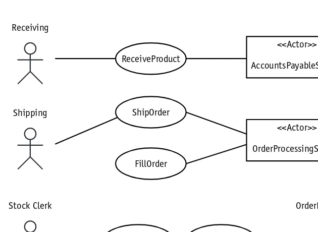
Use Case system ...53
Use Case actors ...53
Use Cases ...54
Use Case relationships ...55
Association notation ...56
Stereotype notation ...56
<<include>> dependency notation ...56
<<extend>> dependency notation ...57
Session 6–Building the Use Case Diagram ...61
Building the Use Case Diagram for the Case Study ...61
Step 1: Set the context of the target system ...62
Step 2: Identify the actors ...62
Step 3: Identify the Use Cases ...63
Step 4: Define the associations between actors and Use Cases ...64
Step 5: Evaluate the actors and Use Cases to find opportunities for refinement ..65
Step 6: Evaluate the Use Cases for <<include>> dependencies ...66
Step 7: Evaluate the Use Cases for <<extend>> dependencies ...66
Step 8: Evaluate the actors and Use Cases for generalization ...67
Session 7–Building the Use Case Narrative ...69
Elements of a Use Case Narrative ...69
Assumptions ...70
Pre-conditions ...70
Use Case initiation ...71
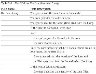
Dialog ...71
Use Case termination ...72
Post-conditions ...72
Additional narrative elements ...73
Writing a Use Case Narrative for the Case Study ...74
Assumptions in the case study narrative ...75
Pre-conditions in the case study narrative ...75
Use Case initiation in the case study narrative ...75
Use Case dialog in the case study narrative ...76
Use Case termination in the case study narrative ...77
Post-conditions in the case study narrative ...77
Session 8–Identifying the Use Case Scenarios ...81
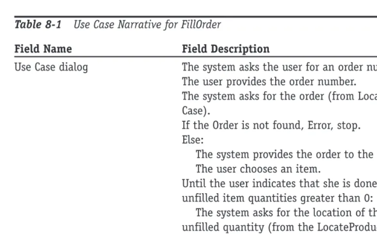
Describing Use Case Scenarios ...81
Why you should care about Use Case scenarios ...82
How to find Use Case scenarios ...83
Finding Use Case scenarios for the case study ...84
Applying Use Case scenarios ...90
Session 9–Modeling the Static View: The Class Diagram ...93
The Object Model ...93
The Class diagram ...94
The Object diagram ...95
Elements of the Class Definition ...95
Modeling an Attribute ...95
Attribute visibility ...96
Creating an attribute specification ...97
Modeling an Operation ...98
Elements of an operation specification ...98
Modeling the Class Compartments ...100
Name compartment ...101
Attribute compartment ...101
Operation compartment ...102
Creating Different Views of a Class ...102
Session 10–The Class Diagram: Associations ...105
Modeling Basic Association Notations ...106
Association name ...106
Association multiplicity ...107
Association roles ...109
Association constraints ...109
Modeling Extended Association Notations ...110
Association class ...110
Reflexive association ...111
Qualified association ...111
Part III—Saturday Afternoon
...116Session 11–The Class Diagram: Aggregation and Generalization ...117
Modeling Aggregation and Composition ...117
Elements of aggregation ...118
Elements of composition ...119
Creating aggregation and composition relationships ...120
Modeling Generalization ...121
Elements of generalization ...122
An illustration: How to model generalization ...124
Session 12–Applying the Class Diagram to the Case Study ...129
Modeling the Inventory Control System for the Case Study ...129
Problem statement: for the inventory control system ...129
Building the Class diagram ...130
Understanding UML Notation for Design Patterns ...133
Using Design Patterns in the Class Diagram ...135
Session 13–Modeling the Static View: The Object Diagram ...139
Understanding the Object Diagram ...139
Introducing Elements of the Object Diagram Notation ...140
Comparing the Object Diagram and the Class Diagram Notations ...140
Applying Object Diagrams to Test Class Diagrams ...142
Test case 1 ...143
Test case 2 ...143
Test case 3 ...145
Test case 4 ...145
Session 14–Modeling the Functional View: The Activity Diagram ...149
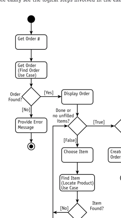
Introducing the Activity Diagram ...149
Modeling workflow and Use Cases ...149
Taking a Look at Activity Diagram Notation ...151
Activities and transitions ...151
Guard condition ...151
Decisions ...152
Merge point ...153
Start and end ...154
Concurrency ...154
Session 15–Applying the Activity Diagram to the Case Study ...157
Building an Activity Diagram for the Case Study ...157
Session 16–Modeling the Dynamic View: The Sequence Diagram ...167
Understanding the Dynamic View ...167
Knowing the purpose of Sequence and Collaboration diagrams ...168
Mapping interactions to objects ...168
Defining the basic notation of the Sequence diagram ...169
Defining the extended notation for the Sequence diagram ...171
Part IV—Saturday Evening ...178
Session
17–Applying the Sequence Diagram to the Case Study ...179Building a Sequence Diagram from a Scenario ...179
Session 18–Modeling the Dynamic View: The Collaboration Diagram ...187
The Collaboration Diagram ...187
Diagram similarities ...188
Diagram differences ...188
Collaboration Diagram Notation ...189
Session 19–Applying the Collaboration Diagram to the Case Study ...193
Building a Collaboration Diagram from a Scenario ...193
Mapping the Sequence and Collaboration Diagram Elements to the Class Diagram ...200
Session 20–Modeling the Dynamic View: The Statechart Diagram ...203
Describing the Purpose and Function of the Statechart Diagram ...203
Defining the Fundamental Notation for a Statechart Diagram ...204
Building a Statechart Diagram ...206
Defining Internal Events and Activities ...210
SUNDAY...214
Part V—Sunday Morning
...216Session 21–Applying the Basic Statechart to the Case Study ...217
Defining Entry and Exit Actions ...217
Defining Send Events ...219
Order of Events ...220
Applying the Basic Statechart Diagram Notation to the Case Study ...221
Inventory control: Problem statement ...221
Session 22–Modeling the Extended Features of the Statechart ...227
Modeling Transition Events ...227
Call event ...228
Time event ...229
Change event ...229
Making events conditional ...230
Send event ...231
Guard conditions as events ...231
Modeling Superstates and Substates ...231
Split of control ...232
Concurrency ...233
Session 23–Applying the Extended Statechart Features to the Case Study ...237
Deriving a Statechart from Sequence Diagrams ...237
Session 24–Modeling the Development Environment ...245
Describing the Purpose and Function of Packages ...245
Packages Provide a Namespace ...246
Defining the Notation for Packages and Package Diagrams ...247
Package stereotypes ...247
Package dependency ...247
Dependency stereotypes ...248
Model elements in a package ...249
Constructing a Package Diagram for the Case Study ...250
Sesssion 25–Modeling the Static View: The Component Diagram ...255
Explaining the Component Diagram ...255
Defining the Notation for Components and Component Dependencies ...256
Component stereotypes ...256
Component interfaces ...257
Component dependencies ...257
Building a Component Diagram for the Case Study ...258
Mapping the Logical Design to the Physical Implementation ...260
Session 26–Modeling the Static View: The Deployment Diagram ...263
Describing the Purpose and Function of the Deployment Diagram ...263
Defining the Notation for the Deployment Diagram ...264
Mapping Software Components to an Architecture ...266
Applying the Combined Diagrams to the Case Study ...266
Part VI—Sunday Afternoon
...276Session 27–Introduction to Web Development with Java ...277
The Value of UML in Web Development ...277
Issues in Using the UML in Web Development ...278
Basic Web Architecture and Static Web Content ...278
Dynamic Web Content ...280
Java servlets ...281
Template pages ...283
Session 28–Analysis and Architectural Design of a Web Application ...287
The Friendly Reminder Case Study ...287 Requirements Gathering ...288
Creating the Use Case diagram ...289 Analysis ...290
Architectural Design ...291
Model View Controller ...291 JavaBeans ...292 MVC pattern in the case study ...294
Session 29–Design of a Web Application ...297
Model 2 Architecture ...297 Uploading Appointments and Contacts ...299 Detailed Design ...300
Querying appointments and contacts ...300 Web technologies on an implementation Class diagram ...302 XML ...302
UML modeling of XML ...303 Appointment XML in the case study ...303 Web Application Extension ...305
Session 30–UML Modeling Tools ...307
Explaining the Purpose and Function of Modeling Tools ...307 Explaining Evaluation Criteria for Modeling Tools ...308
The basics ...309
Type and version of the UML supported ...309
Platform support ...309 Printing ...309 HTML documentation ...309 Repository ...310 Code generation ...310 Integrated editor ...310 Version control ...310
Extended features ...311
Round-trip engineering ...311 Data modeling integration ...311 Customization ...312 XML Metadata Interchange ...312 Team development ...313 Evaluating UML Modeling Tools ...313
UML
Part I
—
Friday Evening
Session 1
What Is the UML?
Session 2
UML and Development Methodologies
Session 3
How to Approach the UML
Session 4
Friday
Evening
I
Session 1
What Is the UML?
Session 2
UML and Development Methodologies
Session 3
How to Approach the UML
Session 4
Session Checklist
✔
Explaining why the UML was created
✔
Defining what is and is not included in the UML specification
✔
Explaining the four-layer metamodel architecture
✔
Explaining the built-in extension mechanisms
✔
Describing how the UML is being refined and extended
T
he Unified Modeling Language (UML) is a hot topic in an even hotter industry. The whole software development industry has been explosive, partly due to the revolutionary nature of software itself, which is driven by worldwide business growth and competition.Establishing Standards
For those who are responsible for delivering these revolutionary business solutions, the challenge is daunting. Every week new developments threaten to make our current skills and experience obsolete. Furthermore, the software industry is relatively young and hasn’t yet established itself as a formal discipline. Consequently, most study is focused on pro-gramming rather than on engineering, with practitioners gravitating toward the tangible implementation products and away from the abstract analysis and design artifacts. But it is this very tendency that has led to many failed systems and disastrous problems.
This need for a more mature industry is behind the drive for the UML and other related standards. Our industry needs a framework for measurable and proven engineering tech-niques. The UML is one of the necessary steps in the right direction. This course helps you understand what this step is and how the UML can help you deliver solutions in a way that will help you and your clients reach a new level of systems development maturity.
The UML is a standard for the creation of models that represent object-oriented software and business systems. It combines the best diagramming practices applied by software devel-opers over the past 40 years. The UML standardizes the notations but it does not dictate how to apply the notations. This approach to the standard provides the greatest freedom for developers’ own styles and techniques, while ensuring consistency in their work products.
Some History behind the UML
The UML is the current stop on the continuum of change in software development techniques. The UML was created out of a storm of controversy over the best methodology to use to spec-ify and to develop software systems. Dozens of methods were (and still are) in use, each with a loyal following.
In 1994, Grady Booch and James Rumbaugh, the two market share leaders in object-oriented (OO) software methods, formally joined forces to develop a notation standard. A year later, they published the Unified Method version 0.8. Ivar Jacobson, yet another leader in object-oriented development, joined the team. The team of Rumbaugh, Booch, and Jacobson were soon after dubbed the “three amigos” within OO circles. At the same time that the three amigos were working on their common notation, the Object Management Group (OMG) was establishing the Object-Oriented Analysis and Design (OOA&D) Task Force. The OMG is the same standards body that defined and still manages the CORBA standard. In June 1996, the task force issued a request for proposal (RFP) for a standardized metamodel to support the exchange of models among modeling tools. By October 1996, a number of the leading application and modeling tool manufacturers, like IBM and i-Logix, had partnered with the three amigos to sponsor the UML proposal to the task force.
What is and is not included in the UML Specification
The UML has a more limited scope than people may assume. The OMG’s RFP was primarily concerned with the development of a metamodelfor object-oriented modeling. A metamodel is a cohesive set of definitions for concepts and their relationships. The metamodel was expected to define an underlying language that could be transmitted between tools that support visual modeling, without constraining the vendors to support a particular method-ology for developing the models.
The UML metamodel
This metamodel, or set of definitions, describes in fairly precise syntax the underlying meaning of each elementused in visual modeling and the relationships among the elements. For example, in the UML metamodel, you find a detailed definition of what a class is; its component parts, attributes, and operations; and the relationships among them. You do not, however, find a process for finding classes or for evaluating a “good” class versus a “bad” class.
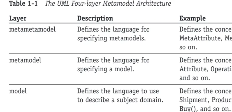
Table 1-1 The UML Four-layer Metamodel Architecture
Layer Description Example
metametamodel Defines the language for Defines the concepts MetaClass, specifying metamodels. MetaAttribute, MetaOperation, and
so on.
metamodel Defines the language for Defines the concepts Class, specifying a model. Attribute, Operation, Component,
and so on.
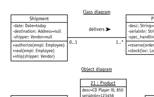
model Defines the language to use Defines the concepts Order, to describe a subject domain. Shipment, Product, Product ID,
Buy(), and so on.
user objects Defines specific subject Defines Order #74653, Shipment domain information. #87649, the product “CD-ROM
435”, the price $50.00, and so on.
Starting from the bottom and working up, the user object layeris where you find a diagram, like a Sequence diagram or Object diagram, populated with the facts from the problem domain like Order #74653 that contains a line item for “CD-ROM 435” with a price of $50.00. The dia-gram is built following the rules defined by the next layer above it, the model layer.
The model layerfully explains the classes that describe the subject domain objects, for example, classes like Order, Shipment, and Product. It tells you what an Order looks like, the fields it contains, the operations it can perform, and so on, without ever telling you about any particular Order. These class definitions conform to the rules specified in the next layer above, the metamodel (2M) layer.
The metamodel (2M) layerdefines what a class is so that the model layer knows how to describe the Order class. It defines a class as a concept having attributes, operations, and associations. It defines an attribute as having a name, a data type, a default value, and con-straints. These definitions in turn conform to the specifications of the metametamodel (3M). The metametamodel (3M) layeris the realm of the philosophers and practitioners of the black arts who determine what makes up a language. Nearly all the definitions at this layer are abstract, that is, they are more like templates that can be used to build a wide variety of concrete concepts.
In case I managed to scare you just now, relax, all you really need to know is the meta-model. That is what this entire course is about, defining the diagrams and the elements used to construct them. Once you understand the diagrams defined by the metamodel layer, you will get enough practice building the model and user object layers to become quite comfortable.
The organization of the metamodel
will find three packagescalled the Foundation, Model Management, and Behavioral Elements packages, as shown in Figure 1-1.
Figure 1-1 Packages of the UML metamodel
Figure 1-1 shows that Behavioral Elements and Model Management depend on the Foundation package. In other words, they won’t work properly if they don’t get help from the contents of the Foundation package (more on the Foundation package in a moment).
The Behavioral Elements package contains everything you need to model behavior like Use Cases, Collaborations, Statecharts, and more.
Model Management explains how to model packages, subsystems, and similar organiza-tional structures.
Figure 1-2 represents the contents of the Foundation package. The Foundation package contains four more packages, the CORE, Auxiliary Elements, Data Types, and Extension Mechanisms packages.
Figure 1-2 The contents of the Foundation package
The Core package defines all the fundamental concepts used in the UML diagrams like Class, Interface, Association, and Data Type. But it also defines some abstract concepts like GeneralizableElement, a high level definition for anything that can implement inheritance, like a class, a Use Case, an actor, and more.
The other three packages support the Core package with items like dependencies; primi-tive data types like integer, string, and time; and some built-in extension mechanisms that I’ll talk about next.
UML Extension Mechanisms
The UML also provides some built-in extensions to the diagram notations. One such tool is called a stereotype.A stereotype appears inside of << >> (guillemets) and characterizes a type of element like a class or relationship without specifying its implementation. For example, you might stereotype a number of classes as <<user interface>>to convey that
Auxiliary Elements Core Data Types
they are all used in the construction of a user interface. But, as Figure 1-3 shows, the indi-vidual classes could be as diverse as Frame, Button, and DropDownList.
Figure 1-3 A stereotype on a class
There are a number of stereotypes already defined in the UML, but you are free to define and use your own. The existing stereotypes are specified in Appendix A of the UML specification.
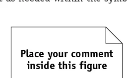
Because no notation can cover every possible type of information, the UML also supports the use of comments.Figure 1-4 illustrates a sample comment icon. You may place as much text as needed within the symbol. The symbol can be placed anywhere on any diagram.
Figure 1-4 Comment notation
Another extension, called a constraint,is used throughout the UML diagrams to limit the use of a model element. You can always spot constraints by the use of { } braces around the text that describes the limitation you want to impose. For example, you might want to limit the values that can be used for the attribute “age” to between 21 and 120. The constraint might look like this: {age > 20 and < 121}. I’ll cover the use of constraints with each dia-gram in the subsequent sessions.
There are two more mechanisms that reach beyond the scope of an introductory book, tagged valuesand profiles.A complete description is available in the UML specification.
Ten Diagrams
Ten diagrams are defined in the UML metamodel. Each is fully described using Class diagrams and textual narrative. A key to the successful application of the UML is in understanding that you can use the notation standard with any number of different development methods, process controls, and quality controls.
In Session 2, I explain the difference between a process and the UML, how they comple-ment one another, and four very different yet popular processes to apply the UML. Session 3 provides an overview of the diagrams. The rest of this course is devoted to explaining the purpose and definition of each UML diagram and their relationships to one another. This understanding should prepare you to apply the models successfully in your own unique environment.
Place your comment inside this figure <<user interface>>
Frame
<<user interface>>
Button
<<user interface>>
The Continuing Refinement and Expansion of the UML
From the outset, the UML was designed to be a public resource. It grew out of a long list of competing notations and methods and continues to be extended and refined. The standard is intended to be a reflection of best practices. Consequently, there is an ongoing need to improve the standard as practices improve and the application of the standard is tested in increasingly diverse and demanding applications.
For these very practical reasons, the UML standard is open for review and change by any-one who wants to contribute to it. The OMG evaluates feedback and incorporates changes into each new release. The OMG has established the UML Revision Task Force (RTF) as a clearinghouse for suggested changes. The suggestions are reviewed for merit, and often scheduled for incorporation into upcoming versions of the product.
The UML is currently in version 1.4. UML version 2.0 is not expected until about the spring of 2003.You can investigate the work being done by the RTF at the UML Revision Task Force Web site (www.celigent.com/omg/umlrtf). You may also access the UML specifi-cations themselves and even download them for free from the OMG Web site: www.omg.org. You will want to refer mostly to the Notation Guide and the Glossary. The Notation Guide covers all the diagram notations and terminology covered in this course and more. It makes a good reference, and it’s free. Regarding the Glossary, you may want to rely as well on the glossary in this text. I found a number of the definitions in the UML Glossary to be circular or simply too thin to be useful.
You can also try some online tutorials at www.celigent.com/omg/umlrtf/tutorials.htm. They aren’t comprehensive, but for free it’s hard to justify a complaint.
R
EVIEWThe UML is a major step toward the standardization of software development. The UML standard has received widespread support from tool vendors and developers alike.
The UML specification describes a metamodel that defines the elements of each diagram, how the diagrams may be assembled, and how they can be extended. The UML standard doesn’t prescribe a process for applying the diagramming
nota-tion. Nor does the standard define the proper use of the notation to create “good” products, or guidelines to avoid bad products. The standard does not dictate how a vendor implements the standard.
The UML metamodel architecture defines four layers: the user object, model, metamodel (2M), and metametamodel (3M) layers.
UML extensions include stereotypes, comments, constraints, tagged values, and profiles.
Q
UIZY
OURSELF1. Who sponsored the UML? (See “Some History behind the UML.”)
2. What part of systems development does the UML define? (See “What is and is not included in the UML Specification.”)
3. What part of systems development is not defined by the UML? (See “What is and is not included in the UML Specification.”)
4. What is a UML stereotype? (See “UML Extension Mechanisms.”)
5. What is a UML constraint? (See “UML Extension Mechanisms.”)
Session Checklist
✔
Explaining methodology
✔
Examining some popular methodologies
A
methodology consists of a process, a vocabulary, and a set of rules and guidelines. The processdefines a set of activities that together accomplish all the goals of the methodology. The vocabularyof the methodology is used to describe the process and the work products created during the application of the process. The rules and guidelines define the quality of the process and the work products.The part of all methodologies that can be standardized is the vocabulary,often expressed in a notation.The UML standard is a common notation that may be applied to many differ-ent types of software projects using very differdiffer-ent methodologies. The variations appear in the use of the UML extensions, like stereotypes, and the emphasis placed on different dia-grams for different types of projects.
One of the challenges inherent in defining a methodology is that it is difficult, if not impossible, to define a single process that works for all projects. For a software development methodology, this would mean a process that works equally well on projects as diverse as arcade games, device drivers, banking, rocket navigation, and life support.
Consequently, even though the UML standardizes the notations gathered from a number of methodologies, the processes used to apply the UML notation are still as diverse as the environments in which they are used.
Some Current Methodologies
The rest of this session is devoted to a brief summary of four of the current methodologies: RUP, Shlaer-Mellor, CRC, and Extreme Programming. They represent the diversity of the cur-rent set of methodologies. I provide a brief summary and then try to point out what I see to
be some strengths and weaknesses in each approach. This should give a fair idea of the opportunities available to you and the factors that may influence your choices.
The list of all methodologies is far too long to cover here, so at the end of the session I’ll point you to a resource where you can check out many of the others and dig a little deeper into the methodologies presented here.
I have selected these four methodologies because they represent the diversity inherent in system development. The Rational Unified Process works well in large projects where quality artifacts and communication are critical. The Shlaer-Mellor Method was developed primarily to address the unique needs of real-time systems long before the UML existed, but has since adopted the UML notation. CRC is almost more of a technique than a method-ology. It was designed as a tool to help people gain an understanding of objects and how they work. Extreme Programming tries to reduce many of the existing development practices to the bare essentials, attempting to optimize the relationship between developers and clients.
The Rational Unified Process
One method that has received a lot of interest recently is the Rational Unified Process (RUP). RUP is the latest version of a series of methodologies resulting from a blending of methodologies. You may have heard the names Objectory Process, the Rational Approach, the Rational Objectory Process, and the Unified Software Development Process. These were all predecessors and have been synthesized into the RUP. Actually, it gets a bit confusing because the Rational Unified Process was a proprietary process within Rational Software, Inc. The merged method was published in 1999 as The Unified Software Development Process. The method has since been made public and the name reverted to the Rational Unified Process (RUP).
The hallmarks of RUP are the two terms incrementaland iterative.These concepts are part of most current methods, but RUP places particular emphasis on their value and their associated artifacts. The goal of the methodology is to deliver an executable release of a product, an increment of the product for every pass, or iteration, through the process. The motivation for this approach is to keep delivery times short and deliveries frequent. This prevents the historical problem of projects that run for months or even years before they actually produce anything. It also supports early review and early problem detection.
Note that in the very early increments, the concept of an executable release is a bit of a stretch. Typically, you might produce prototypes or layouts without anything executable until at least a few iterations into the project. The key is to produce some verifiable output for the clients.
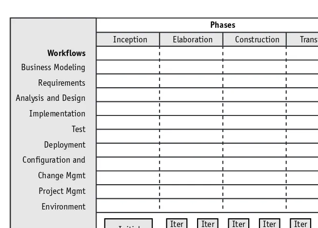
The process is built around the two concepts of project lifecycle phasesand process work-flow.Figure 2-1 shows a two-dimensional matrix. The horizontal axis represents the progress of the project over time. The vertical axis represents the core process workflow. Using this visualization, you can see that in each iteration,or small step through the life of the pro-ject, the team is working through all the steps in the process workflow. In each subsequent iteration, the team digs deeper into each activity in the process workflow.
Figure 2-1 The Rational Unified Process, phases and workflows
For example, the case study presented in this book refers to an inventory control system. The first iteration on this project might focus heavily on requirements and result in a risk assessment, a glossary of inventory control terms, and some screen and forms layouts for receiving and shipping to help the users visualize their requirements. The second iteration might create the Use Case diagram and a set of one or more prototypes from the original screen layouts. A few iterations later you might take one Use Case and actually build the application to support a screen to set the standards for the screen look and feel and to test the basic architecture of the application.
The iterative approach continues until all the requirements have been satisfied and the system is fully implemented.
You may have the impression that the Rational Unified Process is a standard like the Unified Modeling Language. The choice of the name might have been a smart marketing ploy, but that does not make it a standard. There are many other valuable methodologies to consider.
Strengths of the RUP
The emphasis on iterative development and incremental deliveries is a time-tested and valuable approach that prevents many common project problems. However, it must be noted that this approach is common to most of the current methodologies. The process is well defined and supported by the Rational modeling tool.
The artifacts and the roles of the project participants are also very well defined. The process combines many of the best practices from many successful methodologies. The process is comprehensive.
Note
Phases
Workflows
Business Modeling Requirements Analysis and Design Implementation Test Deployment Configuration and Change Mgmt Project Mgmt Environment
Inception Elaboration Construction Transition
Iter #1
Weaknesses of the RUP
In trying to be comprehensive, the RUP becomes very large and difficult, both to learn and to manage.
It is easy to get so caught up in the rules for using the RUP that you forget why you are using it (to deliver software).
A substantial amount of time is spent trying to customize the RUP for each project. Here, too, you run the risk of becoming a slave to the process and losing sight of the reason for the process.
Tool support for the process is limited to Rational’s own products, which are at the high end of the cost range. A few other vendors are now starting to provide limited support.
Shlaer-Mellor Method
The Shlaer-Mellor Method is based on an integrated set of models that can be executed for verification,and an innovative approach to design that produces a system design through a translation of the analysis models.The method is built on a set of well-defined rules for the construction of the diagrams and the translation of those diagrams from analysis to design and finally to implementation. In fact, the most recent generation of modeling tools, like BridgePoint (www.projtech.com/prods/bp/info.html), have created the ability to generate 100 percent of the code.
This achievement is ahead of most other methodologies that generate the operation declarations but cannot provide the method code, the implementation for the operation. The rigorous set of rules also supports verification through simulation. The diagrams can actually be executed to see if they work properly.
One of the primary concepts in Shlaer-Mellor is a domain. A domainis a subject area. Shlaer-Mellor defines three basic types of domains: the application domain, the service domains, and the architectural domain. Each domain has its own unique types of require-ments and diagrams. Together they represent the entire specification for the system.
The Shlaer-Mellor process is broken down into the following steps:
1. Partition the system into domains.
2. Analyze the application domain using object information models, state models, and action specifications (action data flow diagrams — a non-UML diagram).
3. Confirm the analysis through static verification and dynamic verification (simulation).
4. Extract the requirements for the service domains.
5. Analyze the service domains.
6. Specify the components of the architectural domain.
7. Build the architectural components.
The progression from step to step follows a fairly strict set of rules to guide the transla-tion from each version of the diagram to the next. The process sets up a rhythm of build a little and test it, build a little more and test a little more, which helps prevent surprise problems from cropping up deep into the process.
The Shlaer-Mellor Method also places a great emphasis on iterative and incremental development. But this methodology reduces and controls iteration in analysis by confining it to a single domain at a time. Iteration in design is similarly controlled: Modifications to the design are made entirely in the architectural domain and propagated to the entire system through the standardized diagrams.
Reuse is yet another high priority. Because domains are kept completely separate from one another until the final construction steps, they can be transported intact to other sys-tems. This applies particularly to the architectural domain: This domain is commonly reused for other systems that have basically the same loading and performance characteristics.
Strengths of Shlaer-Mellor
By far the greatest strength of the Shlaer-Mellor Method is the ability to test your diagrams through simulation. You actually execute your diagrams.
The process is extremely well defined in terms of rules that govern the construction and testing of the diagrams.
The movement from one step in the process to the next (for example, from analysis-level diagrams to design-analysis-level diagrams) is also defined with enough precision to allow the generation of design diagrams directly from the analysis diagrams. This is a huge time saver and prevents mistakes in the translation. It also speeds up the process of applying changes because they can be propagated through the diagrams automatically.
The method was developed for and maintains a strong emphasis on real-time sys-tems design. As such, it provides support that is largely lacking in other methodolo-gies that gloss over the unique demands of real time in favor of the more common business functionality.
Weaknesses of Shlaer-Mellor
The strengths of the methodology can also be its weaknesses. Like the RUP, the tool support is limited to vendors directly associated with the methodologists. This is changing, but don’t expect it to be quick.
Learning the rules involves a definite learning curve and a serious investment of time and effort. Steve Mellor is currently leading an enhancement to the UML, called Action Semantics, to improve the definition of Statechart diagrams and build much of this knowledge into the UML 1.5 standard. Tool support for this enhance-ment should soon follow.
CRC
CRC stands for Class, Responsibilities, and Collaborators.The CRC methodology was originally developed as a learning tool during the time when object-oriented programming was new; a lot of procedural programmers needed help making the transition to OO thinking. The goal was to provide the simplest possible conceptual introduction to OO modeling.
The heart of the method is the CRC card. A CRC card is a 3-x-5" or 4-x-6" lined index card. The physical nature of the cards emphasizes the division of responsibility across objects. The physical size of the cards also helps to establish limits for the size and com-plexity of the classes. The CRC card technique does not use the UML. Instead it is used to discover information about classes that is then placed into a UML Class diagram.
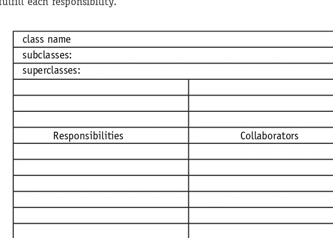
[image:41.639.95.422.278.512.2]Figure 2-2 is a sample blank CRC card. The class name is written at the top of the card. The next two lines are reserved for the listing of superclasses and subclasses. The body of the card is divided in half. The left column or half lists the responsibilities of the class and the right column or half lists the other objects that it works with, the collaborators, to fulfill each responsibility.
Figure 2-2 A CRC card sample
The CRC process requires a team that includes people in two distinct roles: domain expert and object-oriented technology facilitator. The domain experts provide knowledge of the subject area, and the OO facilitator coaches the team through the development of the cards and the eventual model.
The CRC process centers on working through scenarios. The process breaks down into four stages:
class name subclasses: superclasses:
1. Before the Scenario Execution
a. The Problem: Everyone agrees on the problem definition.
b. Brainstorming for Classes: Based on the problem statement, the team identi-fies candidate classes using the vocabulary of the problem.
c. Filtering Classes: The team works on definitions for each class, eliminating synonyms and conflicts.
d. Assigning Cards: Each team member is assigned responsibility for one or more classes.
2. The Scenario Execution
a. Each scenario expresses something that the system is supposed to do. The team walks through the scenario identifying the responsibilities of each class in the scenario.
b. Each discovered responsibility is recorded on the card of the corresponding class.
3. During the Scenario Execution
a. Grouping the Cards: The team identifies similar classes.
b. Scenario List: The team reviews the scenario coverage for completeness.
c. Collaboration Drawings: The cards are combined on a wall or white board to show how they cooperate in the execution of the scenarios.
4. After the Scenario Execution
a. The team reviews the resulting model and plans the implementation.
Strengths of CRC
The simplicity of the method has remained a major selling point and the method has been incorporated into many different methodologies. It is still a valuable tool for helping a programmer transition from procedural to OO concepts.
It is extremely easy to use and very visual. It is difficult for any participant to claim he didn’t know exactly what was going on.
The technique is very responsibility-driven. It keeps the participants focused on the value of an object based on what that object contributes to the proper operation of the system. The result is a system with the minimum number of objects needed to make it work.
The technique helps the participants think like objects and to understand why objects work well or work poorly. This understanding helps ensure a good design.
Weaknesses of CRC
The most significant limitation, however, is also its simplicity. It only really addresses the problem of finding and modeling classes. There is a lot more to com-plete systems development. So the bulk of the work still rests on the programmers. The success of the process is very dependent upon the participants and especially
Extreme Programming
Extreme Programming (XP) shocked a lot of people, including myself, when it first showed up. The goal of XP is much like that of CRC (that is, keep it simple). This is not surprising when you learn that the originator, Kent Beck, was also instrumental in the CRC method. XP does not advocate the UML. I present it here because the goal of this session is to provide you with an understanding of the diversity of methodologies and the views or attitudes that various methodologies hold toward the application of the UML standard.
XP strives to strip away anything that is not essential. XP requires a complete and unwa-vering commitment from the clients to work side-by-side with the programmers. Working through stories or scenarios of how the system should work, the teams eventually develop the entire system. Every iteration of the project (typically one to four weeks each), the teams deliver something functional. The minimum deliverable is a set of tests.
XP basically says that the code is everything, so there is a very heavy emphasis on cod-ing standards and design principles. The process includes numerous standup meetcod-ings to keep everyone on the same page. Furthermore, programmers work in pairs so that they can learn from one another, provide insights, share design alternatives, and generally help each other out.
Because XP is completely devoted to the code, there is very little use of up-front model-ing. If modeling is used, it is usually thrown away when a decision is reached. XP does use the CRC method because of its simplicity and utility. Instead of design up front, the method encourages design through integration and refactoring. In other words, XP advocates believe that as you learn more about the code, you are in a better position to make the design decisions and update your code. In one sense, it could be seen as bottom-up design.
Strengths of XP
XP is the first that I know of that truly cared about the programming environment and its affects on the participants. The bibliography for Extreme Programming Explained, Embrace Change, by Kent Beck, reads more like a sociology text than a programming text. No one since Tom DeMarco, writing the book Peopleware,has devoted as much time to finding ways to make the programming job livable. XP encourages an extremely close relationship between clients and developers. XP faces the fact that change is inevitable and often uncontrollable and builds that
fact into the development approach.
Kent Beck has been brave enough to describe what it really takes to create a high-caliber development environment instead of bowing to the status quo of impossible deadlines, inadequate user involvement, ill-defined requirements, and programmer isolation.
Weaknesses of XP
XP relies heavily on setting up the ideal development environment. It starts from several questionable assumptions: