Article
A Novel Approach for Centralized 3D Radio Resource
Allocation and Scheduling in Dense HetNets for 5G
Control-/User-plane Separation Architectures
Rony Kumer Saha
1,a,*, Yan Zhao
2,b, and Chaodit Aswakul
1,c1 Wireless Network and Future Internet Research Unit, Department of Electrical Engineering, Faculty of Engineering, Chulalongkorn University, Bangkok 10330, Thailand
2 International School of Engineering, Faculty of Engineering, Chulalongkorn University, Bangkok 10330, Thailand
E-mail: a[email protected] (Corresponding author), b[email protected], c[email protected]
Abstract.This paper presents a centralized 3-dimensional radio resources (namely, time, frequency, and power) allocation and scheduling approach for control-plane and user-plane (C-/U-plane) separation architectures for fifth generation mobile networks. A central station is considered where schedulers of all base stations (BSs) are located. We consider a multi-tier network that comprises of a macrocell BS (MCBS), several outdoor picocell BSs, and a number of indoor femtocell BSs (FCBSs) deployed in a number of multi-storage buildings. The system bandwidth is reused in FCBSs within each building orthogonally. In contrast to the conventional almost blank subframe, we consider a fully blank subframe based time-domain enhanced intercell interference coordination to split completely C-/U-plane traffic such that the control-plane can be served only by the MCBS and the user-control-plane of user equipments by their respective BSs. We propose two power management schemes for FCBSs based on whether or not the coordinated multi-point communication with joint transmission (JT CoMP) is employed during off-state of a FCBS and develop a power control mechanism for both a single user and multi-user per FCBS scenarios. An optimal value of average activation factor (OAF) for a FCBS is derived to trade-off its serving capacity and transmit power saving factor. It is shown that in order to improve the network capacity, a FCBS needs to operate at an average activation factor (AAF) greater than its OAF using JT CoMP to serve neighboring on-state FCBSs during its normal off-state, whereas at an AAF less than the OAF to improve the energy efficiency. With a system level simulation, we show that the capacity of a FCBS increases, whereas its power saving factor decreases linearly with an increase in its AAF because of serving increased traffic, and an OAF of 0.5 for the capacity scaling factor 12and greater than 0.5 for
1are found.Keywords:3D, 5G, centralized, control-/user-plane separation, HetNet, resource scheduling, small cell.
ENGINEERING JOURNAL Volume 21 Issue 4
Received 1 March 2017 Accepted 15 May 2017 Published 31 July 2017
1.
Introduction
1.1. Background
Radio resource allocation and scheduling (RRAS) plays a crucial role on achievable capacity, spectral efficiency, and energy efficiency of cellular networks. For providing a high data rate service demand and network capacity, supporting a large traffic volume, and achieving a high spectral and energy efficiencies of fifth generation (5G) cellular networks, the development of an effective RRAS strategy for the major 3-dimensional (3D) radio resources (i.e., time, frequency, and transmit power) has been found inevitable due to their limited availability. Though most existing research addressed either 1-dimensional or 2-dimensional radio resources of these three in decentralized network architectures (i.e., distributed heterogeneous base station (BS) cellular network architectures), a number of research addressed 3D RRAS by now.
For example, authors in [1], proposed a joint power-frequency-time resource allocation algorithm for wireless mesh networks. Whereas, authors in [2] proposed a joint time-frequency-power resource allocation for low-medium-altitude platforms based Worldwide Interoperability for Microwave Access (WiMAX) networks to improve the performances and services of emergency communications. In [3], authors also proposed a joint subchannel and power allocation algorithm for the downlink of an orthogonal frequency-division multiple access (OFDMA) femtocell (FC) and macrocell (MC) based network. However, decentralized architectures lead to scaling small cell base stations (SCBSs) with the number of user equipments (UEs) and the amount of traffic volume per unit area, which cause such architectures to suffer from a number of pitfalls, e.g. increase in network operational expense, severe inter-cell interference, and low system hardware resource utilization rate. Hence, decentralized architectures are not widely considered suitable for 5G, and the idea of centralized cellular architecture has come into being [4].
1.2. RelatedWork
Numerous proposals on centralized wireless networks are existing in literature, e.g. cloud radio access network architecture [5], wireless network cloud [6], and LightRadio [7], which are based on decoupling radio frequency and baseband processing tasks from physical nodes and shifting them to a centralized location. Similar to these architectures, authors in [4] also proposed a super BS based centralized architecture for 5G where the global centralized resource management center allocates resources to virtual BSs. Recently, software defined networking (SDN) has been considered as an effective centralized resource management for 5G. Authors in [8] proposed SDN-based resource management algorithms for 5G heterogeneous networks (HetNets) that exploit an SDN controller’s global view of the network and take optimized resource allocation decisions. Further in [9], authors proposed to combine network function virtualization (NFV) and SDN to achieve better radio resource management performance in fourth generation (4G) and 5G HetNets.
Besides, because of an expected ultra-densification of small cells (SCs) in 5G networks, extensive research on SC energy efficiency has been ongoing. Authors in [10] proposed an energy efficient small cell activation mechanism to offload traffic from the MC to SCs in energy saving mode to reduce the total energy consumption of the network. In [11], authors quantified the tradeoff between energy consumption and throughput in a heterogeneous cellular network by considering SCBSs with four distinct power-saving modes. Authors in [12] studied the on and off (on/off) operation of SCBSs to enhance energy efficiency by applying belief propagation optimization framework into on/off operation of access points.
1.3. ConsiderationandContribution
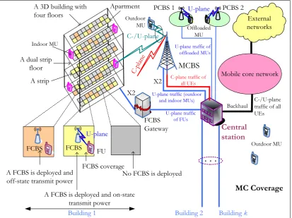
We consider a multi-tier network that comprises of a MCBS and a number of outdoor picocell BSs (PCBSs) and indoor femtocell BSs (FCBSs). All FCBSs are deployed within multi-storage buildings. A central station is considered where schedulers of all BSs are located, and the RRAS of C-plane and user-plane (U-plane) traffic of all BSs is performed. Assume that the distance between neighboring buildings and external wall penetration loss of any buildings are significant enough to overcome co-channel interference between FCBSs of neighboring buildings when reusing the same frequency in them. Hence, we consider reusing fully the whole system bandwidth in FCBSs within each building by allocating them orthogonally in any transmission time interval (TTI).
To split C-/U-plane completely such that the C-plane of all UEs is served only by the MCBS, and the U-plane of a UE is served by its respective BS, we consider a fully blank subframe (FBS) as opposed to an almost blank subframe (ABS) based time-domain enhanced inter-cell interference coordination (eICIC) to avoid co-channel cross-tier interference. We propose two transmit power management schemes for FCBSs based on whether or not coordinated multi-point communication with joint transmission (JT CoMP) is employed during the off-state of a FCBS. The JT CoMP is considered during the off-state of any FCBSs to increase the received signal strength at a UE of any FCBSs with an active traffic request to improve the network capacity. However, to improve the energy efficiency, FCBSs with no active traffic requests are considered switching off their transmit powers during their off-states. A transmit power control mechanism of FCBSs is proposed where the on-state and off-state of a FCBS is modelled as conventional on/off traffic source model for both single user and multi-user per FCBS. An optimal value of average activation factor (AAF) of a FCBS is derived to trade-off its capacity and transmit power saving.
With a system level simulation, the impact of varying the AAF of a FCBS on its capacity and transmit power saving performances is analyzed, and an optimal value of AAF (OAF) is presented. Also, to improve the serving capacity only, a FCBS needs to operate at an AAF greater than its OAF using JT CoMP, whereas an AAF less than the OAF is required to improve only the energy efficiency. In addition, the impact of varying the number of FBSs per FBS pattern period (FPP) on the overall system capacity as well as FC capacity is also shown. Since the delay from switching on/off operation of transmit power of a FCBS as well as the delay from processing UE traffic requests by exchanging control signaling between the MCBS and a FCBS influence greatly the capacity and transmit power saving of a FCBS, these effects are captured by varying AAF from 0 to 1 (i.e., switching the transmit power of a FCBS from always on-state to always off-state) over an FPP.
The paper is organized as follows. In section 2, the system architecture, operation, and mechanism of the proposed centralized radio resource allocation and scheduling (CrrAS) are presented. In section 3, we present two transmit power management schemes for FCBSs based on whether or not the JT CoMP is considered during the off-state of any FCBSs. The modelling of transmit power of any FCBSs and the effect of FBS and switching and processing delay are given in section 4. Section 5 covers the problem formation, including multi-tier network model, capacity estimation, transmit power saving factor of FCBSs, optimal average activation factor of FCBSs, effect of power management schemes on OAF, and proportional fair scheduling. Simulation parameters and assumptions are given, and performance evaluations are carried out in section 6. Finally, we conclude the paper in section 7. The list of abbreviations is given in Table 1.
2.
Proposed Centralized Radio Resource Allocation and Scheduling System Architecture,
Operation, and Mechanism
2.1. System Architecture and Operation
PCBSs, and femto UEs (FUs) by FCBSs. All these U-plane traffic is then routed through the central station, then backhauls, mobile core networks, and finally to external networks. However, C-plane of all UEs under the coverage of the MCBS is served by only the MCBS, and routed through the central station, then mobile core networks via backhauls, and finally to external networks.
Table 1. A list of abbreviations.
Abbreviation Full Form
2D 2-Dimensional
3D 3-Dimensional
3GPP Third Generation Partnership Project
4G Fourth Generation
5G Fifth Generation
AAF Average Activation Factor ABS Almost Blank Subframe
BS Base Station
C-/U-plane Control-plane and User-plane CoMP Coordinated Multipoint C-plane Control-plane
CSG Closed Subscriber Group
CUSA Control-plane and User-plane Separation Architecture
dB Decibel
dBi Decibel Relative to an Isotropic Radiator dBm Decibel-Milliwatts
eICIC Enhanced Inter-Cell Interference Coordination ETSI European Telecommunications Standards Institute FBS Fully Blank Subframe
FC Femtocell
FCBS Femtocell Base Station FPP FBS Pattern Period
FU Femto User Equipment
HetNets Heterogeneous Networks
JT Joint Transmission
MC Macrocell
MCBS Macrocell Base Station MU Macro User Equipment
OAF Optimal Average Activation Factor on/off on and off
PC Picocell
PCBS Picocell Base Station
RB Resource Block
SC Small Cell
SCBS Small Cell Base Station TTI Transmission Time Interval
UE User Equipment
U-plane User-plane
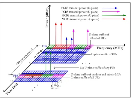
[image:4.595.129.469.169.664.2]characteristics, and fairness factor. To serve U-plane traffic, we consider one proportional fair scheduler for all outdoor and indoor MUs, one for all offloaded MUs, and one for all FUs per building. Also, to serve C-plane traffic, one proportional scheduler for all UEs is considered.
Because of allocating resources to all MUs and FUs at the central station, Unlike traditional decentralized CUSA [15-16], the main advantage of CrrAS is that there is no need for exchanging control signaling between C-plane and U-plane BSs for synchronization, FCBSs’ transmit power switching on/off, and SC discovery and wake up mechanism required in CUSA. This results in reducing the control signaling overhead and increasing the user data traffic capacity in the backhaul.
2.2. Mechanism
We consider a FBS based eICIC to avoid transmitting any control signals, in contrast to a traditional ABS, to switch off the transmit power of a FCBS completely during an FBS. A static allocation of the number of FBSs per FPP, comprising 8 TTIs, by a time-domain scheduler at the central station is considered. Also a number of on/off transmit power management schemes are considered, which is detailed in a following section. All indoor MUs, offloaded MUs, and outdoor MUs in the MC coverage are allocated to RBs orthogonally. The whole system bandwidth of the MCBS is reused in FCBSs per building. Like all categories of MUs, RB allocations to all FUs within a building are considered orthogonal. If a MU is detected within any buildings, the time-domain FBS based eICIC is applied to FCBSs of that building to avoid co-channel interference between indoor MUs and FUs.
External networks
FCBS
Gateway Central
station
MCBS
U-plane traffic of FUs
Mobile core network
C-plane traffic of all UEs
U-plane traffic (outdoor
and indoor MUs) C-/U-plane
traffic of all UEs
C-pl ane
X2 PCBS 1
U-plane traffic of offloaded MUs
Apartment
A FCBS is deployed and on-state transmit power
No FCBS is deployed A dual strip
floor A strip
A 3D building with four floors
FCBS coverage
Indoor MU
PCBS 2
FU FCBS FCBS
A FCBS is deployed and off-state transmit power
Offloaded MU Outdoor
MU
C-/U-plane
U-plane
U-plane
X2
Outdoor MU
MC Coverage
Building 1
. . .
Building 2 Building k
Backhaul
Fig. 1. System architecture of a multi-tier heterogeneous network for CrrAS with k multi-storage buildings.
[image:5.595.92.506.340.649.2]FCBS has only two states, either zero or maximum, based on the FU traffic requests and other factors as shown in Fig. 4.
TTI RB
Time
F
re
qu
en
cy
. . .
. .
.
All categories of MUs can be scheduled
All outdoor MUs, offloaded MUs, and FUs in buildings can be scheduled
FBS Non-FBS
Fig. 2. FBS based time-domain eICIC.
Frequency (MHz)
Tim e (m
s)
P
ow
er
(
dB
m
)
C-plane traffic of all UEs
RB 180 kHz
FBS
TTI
U-plane traffic of offloaded MUs
U-plane traffic of outdoor and indoor MUs U-plane traffic of FUs
No U-plane traffic of any FUs
. .
.
. . .
FBS pattern perio
d
0
8
5
9 10
FCBS transmit power (U-plane)
MCBS transmit power (U-plane) MCBS transmit power (C-plane) PCBS transmit power (U-plane)
FBS
TTI
Fig. 3. An illustration of 3D RRAS concerning a FCBS.
3.
FCBS Transmit Power Management
[image:6.595.119.475.121.254.2] [image:6.595.79.517.284.610.2]FCBSs to offer joint transmission (JT) coordinated multi-point (CoMP) communications to improve the UE’s received signal strength.
Hence, when network capacity or spectral efficiency is concerned, cooperative or opportunistic resource allocation can be explored during the off-state of any FCBSs such that neighboring FCBSs with no active traffic requests can form a CoMP set to help increase the received signal strength of any FCBSs with an active traffic request. In contrast, when energy efficiency is concerned, FCBSs with no active traffic requests can be muted for transmission by switching their transmit power off. Hence, based on whether or not a FCBS is considered transmitting power during its off-state, we propose two power management schemes of any FCBSs as described in the following.
3.1. Without Exploiting JT CoMP during Off-state of a FCBS Transmit Power
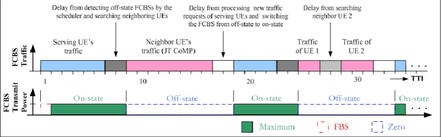
In this scheme, FCBSs are not always active. Rather, each FCBS is switched on/off based on active data traffic requests. An FCBS is considered switching on as long as an active data traffic session exists, and switching it off after a certain number of TTIs as shown in Fig. 4,which can be modeled as the on/off traffic source model. Switching on/off any FCBSs is governed by the respective scheduler at the central station. When there is no further active data requests from a UE (i.e., FU) under the coverage of a FCBS, the scheduler then sends a power-off message to that FCBS to keep its transmit power switched off until any further request is made by any UEs. In switching on an FCBS, a UE first sends a random access channel request
to the MCBS in the uplink. Assuming that a mechanism exists for selecting an appropriate FCBS by the MCBS, the MCBS informs of the UE request to the corresponding frequency-domain scheduler at the central station. The scheduler then sends a power-on message to the FCBS to which the FU may get connected with in the downlink and creates necessary data bearers through that FCBS. The scheduler also informs the UE over the backhaul via the MCBS to create relevant radio resource control (RRC) connections with the FCBS. After acknowledging the RRC connection complete message from the FCBS, the UE then starts communicating via the FCBS to mobile core networks and then to external networks.
Fig. 4. An illustration of the transmit power on/off scheme of a FCBS without exploiting JT CoMP during its off-state
.
3.2. With Exploiting JT CoMP during Off-state of a FCBS Transmit Power
Fig. 5. An illustration of the transmit power on/off scheme of a FCBS with exploiting JT CoMP during its off-state.
An off-state FCBS serves a UE of one of its nearest neighbor FCBSs either at the same frequency as that of the serving FCBS or at a different frequency in any TTIs based on the operator’s policy for an efficient bandwidth utilization. Typically, the frequency-domain scheduler has the knowledge of physical cell identity (PCI) and on/off-state status of each FCBS in order to determine and inform any off-state FCBSs to serve during its off-state. Since the scheduler has all the UEs’ CSIs and traffic data rate demands, if there exists more than one UE to serve during its off-state, the off-state FCBS is being informed by the scheduler to serve the UE with the maximum service data rate demand, for example. Further, if all the neighbor UEs has the same service data rate demand, the off-sate FCBS may serve any UEs by choosing randomly.
Once an off-state FCBS is chosen to serve any neighbor UEs, it continues to serve the same UE so long as either that UE’s data transmission is finished, or until there is a new request from its own serving UE. Hence, even though other neighbor UEs’ either CSIs or data rate demands are higher than that of the UE, which has been already chosen by the off-state FCBS, it continues to serve it in order to reduce control signaling overhead (Fig. 5). Also, if during the off-state, the existing UE’s (UE1) traffic is finished to serve, the off-state FCBS starts searching to serve another neighboring UE (UE2) if any, and continues to serve as long as any new traffic requests from its own serving UEs is not made. When any such new request is made, the FCBS then stops serving the neighboring UE and starts serving its own UE. All these activities are shown in Fig. 5 where UE 1 and UE 2 are neighboring UEs served by a FCBS during its off-state.
So, based on switching on/off operations (i.e., if there is any FU traffic requests) of transmit power of FCBSs during the off-state, inactive FCBSs can be considered transmitting other neighboring active FUs at any RB i in TTI t to enhance the overall network capacity and spectral efficiency further while keeping the energy efficiency within a limited range. Hence, a tradeoff between the network capacity and energy efficiency is needed, which is addressed in a later section by deriving an OAF.
4.
Modeling FCBS Transmit Power and Effect of FBS and Switching and Processing
Delay
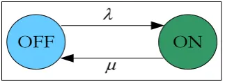
4.1. FCBS Transmit Power Modeling
The 3rd Generation Partnership Project (3GPP) European Telecommunications standards Institute (ETSI)
[image:8.595.74.525.99.239.2]in Fig. 6, wheredenotes the power off-state to on-state transition rate, and denotes the power on-state to off-state transition rate of any FCBSs.
OFF
ON
Fig. 6. Two-state on/off transmit power model for a FCBS.
The randomness in switching any FCBS’s transmit power to on/off states can be modelled by the average duration of each state such that the average time at an on-state is given by
1
and at an off-state by1
[17]. Hence, the AAF, which is defined as the probability that a FCBS is at the on-state, is given by,
1 1 1
state on
P
(1)Hence,
state 1
off
P
(2)
For a single FU per FCBS, because a FU also has two states (i.e., there is either a traffic request or not at all), the FU state diagram is the same as its FCBS’s on/off state diagram (Fig. 6). Hence, for a single FU per FCBS, the average on/off state probabilities of transmit power of any FCBSs are given by Eq. (1) and Eq. (2).
However, for multi-user per FCBS, finding the values of on-state and off-state durations is not immediate since there exists more than one UE, and the FCBS may have to be active with an activity factor of 100% at the extreme case. To find the on/off state probabilities of FCBS for such multi-user per FCBS scenario, a more general and simple way is to calculate the probability of no UE traffic requests in progress such that the probability of off-state can be given by,
off
-
state
1
p
0
P
(3)And the probability of on-state can be given by,
p
p
p
N
sP
on
-
state
1
2
(4)where
p
0
,
p
1
,
p
2
,
,
p
N
s represent the state probability for is=0,1,2, …, Ns. Ns is the number ofusers with in-progress traffic with the FCBS. The values of these probabilities can be found following the Birth-Death process as follows.
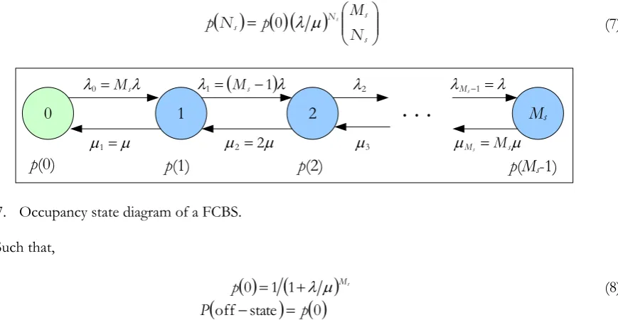
Consider that there are Ms users per FCBS of which Ns users have in-progress traffic with the FCBS at
any time t as shown in Fig. 7. Let
Nsand
Nsdenote the birth rate and the death rate respectively. Then,according to [17, 19-20], the followings hold.
otherwise ,
0
0
, s s
s s N
M N N
M
s
(5)
[image:9.595.217.379.119.178.2]And the probabilities for any Ns (Fig. 7) can be given by,
s s N s N M p Np 0
s(7)
0
1
0 Ms
1
2
1 Ms1 22
M
s Ms1
Ms Ms
2
3
. . .
p
(0)
p
(1)
p
(2)
p
(
M
s-1)
Fig. 7. Occupancy state diagram of a FCBS.
Such that,
Msp 0 1 1 (8)
Msp P
1 1 0 state off (9)
MsP
1 1 1 state on (10)Hence, for a particular duration of time Ts, the average on-state duration of any FCBSs is given by,
s state
on
T
t
(11)Similarly, the off-state duration is given by,
sstate
off
1
T
t
(12)For evaluation, we consider an average value of probabilities, e.g. given by Eq. (1) and Eq. (2), per FCBS per FPP so that an average value is estimated in ratio of the number of TTIs per FPP per FCBS.
4.2. Effect of FBS and Switching and Processing Delay
Let onoff denote an average aggregate delay per FPP T from switching on-state to off-state of any FCBSs, whereas offondenote delay from switching off-state to on-state, for traffic request processing of any FUs, e.g. discovery of any FCBSs and C-/U-plane cooperation for synchronization. Let fbsdenote percentage duration of FBSs, and sand nsdenote percentage average durations of any progress active and in-active FU traffic respectively per FPP T.
The average on-state duration of any FCBSs can be given by,
TT t off on s state on (13)
Similarly, the average off-state duration of any FCBSs is given by,
T [image:10.595.90.525.106.331.2]Equivalently,
T
t
offstate
ns
offon
fbs
(15)Such that,
state off state
on
t
t
T
(16)5.
Problem Formulation
5.1. Multi-Tier Network Model
Consider that there are M RBs in the system bandwidth, and N MUs in the system. Let SP denote the
number of PCs in the MC coverage. Consider that the number of offloaded MUs is uniformly distributed in the interval [1, UOFL]. If all PCs have an equal number of offloaded MUs UP, i.e.qUPqUP, then the total
number of offloaded MUs, UOFL=SP×UP. However, in general, Uq
Pis a random variable, which varies from one PC to another, and the realization of q
UPfor a PC is mutually independent from the others. If µMI denotes the ratio of the number of indoor MUs, then the total number of indoor MUs is UMI=µMI×N,
outdoor MUs is UMO= N-UOFL-UMI, and MUs served by the MC is UM=UMO+UMI.
Let NM denote the set of indices of all MUs such that NM={1, 2, 3,…, N}. Denote NMO, NP, and NMI respectively the set of indices of all outdoor MUs, offloaded MUs, and indoor MUs. Note that NM is partitioned randomly into three disjoint subsets NMO, NP, and NMI. Let L denote the maximum number of buildings in a MC coverage, and SF denote the number of active FCs in each building. Assuming that SF is the same for all buildings, the total number of active FCs in the system is SFS=L×SF. Consider that the number of FUs in buildings are independent and uniformly distributed in the interval [1, UF]. In general, UF is a random variable, which varies from one building to another, and the realization of UF for a building is mutually independent from the others where a realization is defined as a simulation run time.
Let Uw
F denote the number of FUs served by a FCSFw in a building such thatwUFw0, UFw,max. If all FCs have an equal number of FUsUFC, i.e.wUFw UFC, then the total number of FUs in any buildings, UF=SF×UFC. However, in general, Uw
Fis a random variable, which varies from one FCBS to another, and
the realization of Uw
Ffor a FCBS is mutually independent from the others. If each FC in a building serves one UE, i.e.UFC1, the total number of FUs in a building is UF=SF, and in the system is UFS=L× UF.
Let NF denote the set of all FU indices in a building such that NF={1, 2, 3,…, UF}.
The realization of MUs served by the MC and PCs are not mutually independent since MUs served by PCs are MUs offloaded from the MCBS, and the schedulers have a complete knowledge when a MU is offloaded. FC buildings and PCs are located randomly and uniformly in the MC area. The indoor MUs are distributed randomly and non-uniformly within buildings. All outdoor MUs, offloaded MUs, and FUs are distributed randomly and uniformly within their respective BSs’ coverage area.
Let T denote simulation run time with the maximum time of Q (in time step each lasting 1 ms) such that T={1, 2, 3, …, Q}. Let TFBS denote a set of FBS indices over all FPPs for Q TTIs, and TFPP denote
the number of subframes per FPP such that TFBS T and TFBS={t: t=(v×TFPP)+n; v=0, 1, 2, …, Q/TFPP;
n=1, …, TFBS} where TFBS=1, 2, …, TFPP corresponds to FBS patternsfbs=1/TFPP,2/TFPP, …, TFPP/TFPP
respectively. Let tFBSand tnonFBSdenote respectively an FBS and a non-FBS such that tFBSTFBS and
FBS non
t T\TFBS.
Let ton-state denote a set of subframes over all FPPs for T, and ton-state denote the number of subframes
per FPP such that ton-state T. In general, ton-state is an integer random variable, which varies from one TFPP
to another for Q TTIs and depends mainly on in-progress active UE traffic requests and characteristics over any TFPP.
LetdMU,dPC, and dFCL denote respectively the distances of any MUs, PCs, and buildings from the MCBS,
and dFC denote the distance between a FCBS and a FU. The distances of all UEs of each category in a
realization are generated following the respective distribution functions as mentioned earlier. The received signal-to-interference-plus-noise ratio (SINR) for a UE at RB i in TTI t at power p can be expressed as
ti p ti p ti p
ti pp i
t,, Ptr,, (Ns,, I,, )H,,
(17)
where tr , ,ip t
P is the transmission power; s , ,i p t
N is the noise power; It,i,pis the total interference signal
power; and Ht,i,pis the link loss for a link between a UE and a BS at RB i in TTI t at power p, which can be
expressed in dB as
dB ( ) ( ,, ) ( ,, ,, ),
,i p t r F ti p ti p ti p
t G G L PL LS SS
H (18)
where(GtGr)and LFare respectively the total antenna gain and connector loss, andLSt,i,p,SSt,i,p, and
p i t
PL,, respectively denote shadowing effect, small-scale Rayleigh fading or Rician fading, and distance dependent path loss between a BS and a UE at RB i in TTI t at power p. Let denote implementation loss factor. Using Shannon’s capacity formula, a link throughput at RB i in TTI t at power p in bps per Hz is given by [21-22],
dB 22 , 4 . 4 dB 22 dB 10 , 10 1 log dB 10 , 0 , , , , 10 dB 2 , , , , , , ,, p i t p i t p i t p i t p it tip
(19)
Since any FCBSs transmits only u-plane traffic during its on-state, using Eq. (13), the aggregate average capacity of FCBSs is given by,
Q t M i p i t p i t 1 1 , , , , sFC
(20)
wheret,i,p
t,i,p
denotes the throughput response of all FUs in tton-state over M RBs.The total system capacity over the whole system bandwidth for Q TTIs can be expressed as the sum throughput of all UEs as follows.
Q t M i p i t p i t 1 1 , , , ,S
(21)
where
and
are responses of all MUs in tTFBS, outdoor and offloaded MUs in tT\TFBS, and allFUs in tton-state.
5.3. FCBS Transmit Power Saving and Optimal Average Activation Factors
5.3.1. FCBS transmit power saving factor
Using Eq. (13) and Eq. (14), the power saving factor of any FCBSs can be given by the average on-state and off-state durations as follows.
on state off state
state
off
t t t
(22)
11 T T
Hence, the percentage power saving factor is given by,
1
100% (24)
5.3.2. FCBS optimal average activation factor
Since both the capacity and power saving factor of any FCBSs are proportional to AAF, an OAF that can trade-off these demands can be defined as its corresponding value of a point where the capacity and power saving responses are equal so that the optimization problem can be formulated as follows.
0to subject maximize
max FC,
FC
whereFC,maxdenotes the maximum capacity of FUs in t
T over M RBs, whereas FCimplies the actual aggregate capacity of FCs as given by Eq. (20).From Eq. (20), since FCis a function of link quality irrespective of the value of s,FC,maxcan be defined and fixed in prior as a system parameter by setting the maximum value of the average link quality of an FUlqbased on, e.g. the operating band of FCBSs such that FCFC,max. The inequality comes from the fact that the average actual link quality of any FUs is upper bounded bylq, which is incorporated in
FC
by a capacity scaling factorsuch that01.
The solution of the above optimization problem for s can be found as follows, which is proved in the following.
FC FC,max
* 1
Proof. From Eq. (20),
s lq maxFC,
QM
Applying the constraint,
max FC, FC
max ,
1FC FC
FC FC,max
1
(25)
From Eq. (13),
off on s
Assuming sonoffsuch thats. Hence, by omitting the inequality with as explained above and using Eq. (20), FC can be expressed in terms of FC,maxas follows.
max , FC FC
Further from Eq. (25), the solution for
*can be found as follows.
FC,max FC,max
* 1
* 1 (26)
2 1
*
(27)
5.3.3. Effect of power management schemes on OAF
When considering JT CoMP to improve network capacity further from that can be achieved at*,
the solution of the above optimization problem can be given by,
* * nc
FC FC,max
*
nc 1
(28)
wherenc* denotes an OAF that corresponds to the improved network capacity set by the network
operator.
Similarly, when considering energy efficiency to improve further from that can be achieved at*,
the solution for an OAF can be given by,
FC FC,max
*
ee 1
(29)
whereee* denotes an OAF that corresponds to the improved energy efficiency also set by the network
operator. Note that a FCBS operates as a typical single network entity to serve UEs only within its coverage when considering its AAF less than that of its OAF*. Hence, there is no need for JT CoMP to address
energy efficiency improvement.
5.4. Proportional Fair Scheduling
Since proportional fair scheduler provides an optimal trade-off between fairness and throughput performances, we consider it to schedule time and frequency resources among UEs. Based on the current and past average throughputs of a UE, it schedules a UE
x
i
t
in TTI t at RB i with the maximumperformance metric given by [23],
t
t
t
x xi xi
x
i argmax
,
~, (30)wherex,i
t and ~x,i
t represent respectively the current and past average throughputs of UE x at RBi in TTI t. The past average throughput ~x,i
t at RB i is updated in every TTI as follows [24] where tcdenotes adjustable time constant.
t x x t t t x x t t t t t i i x i i x i x i x , 1 1 ~ , 1 1 1 ~ 1 ~ c , , c c , , (31)6.
Simulation Parameters, Assumptions, Performance Results
6.1. Simulation Parameters and Assumptions
6.2. Performance Results
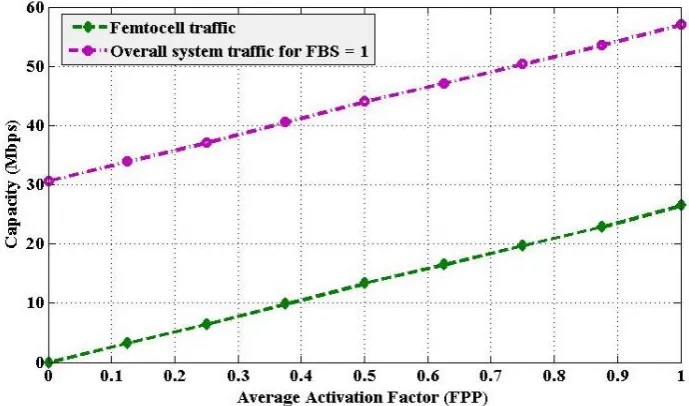
For simplicity in evaluation, because of considering the average value of probability of each factor over an FPP, influencing on-state and off-state durations, we consider one FCBS for performance evaluation. However, this will not affect the performance trends as indoor channels are less susceptible to Doppler Effect and delay spread because of less movement of objects and small coverage of a FC. We defineFC,max as the average sum throughputs of FUs in tT over M RBs per realization. Since we consider one realization per FBS,FC,maxFC.
From Fig. 8, it can be found that the capacity of a FC increases linearly with an increase in its AAF (s), which influences directly the overall system level capacity. The maximum capacity of a FC attains when the FC serves over the whole FPP. However, this is possible only if there is no existence of MU within the building such that the FCBS can be allowed to transmit in all TTIs of any FPPs. In Fig. 8, the overall system capacity of all UEs is shown for FBS=1. However, irrespective of the number of FBSs per
Table 2. Default simulation parameters and assumptions.
Parameter and Assumptions Value
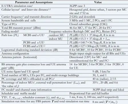
E-UTRA simulation case1 3GPP case 3
Cellular layout2 and Inter-site distance1,2 Hexagonal grid, dense urban, 3 sectors per MC
site and 1732 m Carrier frequency2 and transmit direction 2 GHz and downlink
System bandwidth and cells 5 MHz and 1 MC, 2 PCs, and 1 FC
Type of FCs Closed subscriber group (CSG)
Total BS transmit power1 (dBm) 46 for MC1, 37 for PC1, 20 for FC1
Fading model1 Frequency selective Rayleigh (MC and PC), Rician (FC)
Path loss (PL) MCBS and a UE1 outdoor MU PL(dB)=15.3 + 37.6log10R, R is in m
indoor MU PL(dB)=15.3 + 37.6log10R + Low
PCBS and a UE1 PL(dB)=140.7+36.7log10R, R is in km
FCBS and a UE1,2 PL(dB)=127+30log10(R/1000), R is in m
Lognormal shadowing standard deviation (dB) 8 for MCBS2 , 10 for PCBS1, 10 for FCBS2
Antenna configuration Single-input single-output for all BSs and UEs Antenna pattern (horizontal) Directional (1200) for MC1 and
omnidirectional for PC1 and FC1
BS antenna gain plus connector loss and UE antenna gain2 (dBi)
14 for MCBS2, 5 for PCBS1, 5 for FCBS1, 0
for UE
UE noise figure2and UE speed1 9 dB, 3 km/hr
Total number of MUs, UEs per FC, and multi-storage buildings 30, 1, and 1 PC coverage and MUs offloaded to all PCs1 40 m (radius), 2/15
Percentage of indoor MUs1, external wall penetration loss1 (Low), and 3the value of β
35% , 20 dB, and 0.6
FC model2 and channel state information 3GPP dual strip and Ideal
Scheduler and traffic model Proportional Fair and full buffer
TTI1, T, onoff, scheduler constant (tc), and offon 1 ms, 8 ms, 0, 100 ms, and 0 respectively
Simulation run time for any FBS pattern T and total simulation run time 8 ms and (T ×|fbs|)
taken 1from [26] , 2from [25], and 3from [27-29].
FPP, the aggregate capacity of all MUs does not change considerably as shown in Fig. 9. Hence, the system level capacity shows also a linear response and increases with an increase in AAF of the FCBS.
[image:15.595.73.522.299.664.2]better channel condition of offloaded MUs than that of outdoor MUs. Since an indoor MU experiences a high external wall attenuation loss of a building, they are relatively less scheduled and can gain lower throughput than that of other MU categories.
The number of FBSs per FPP has a negligible impact on the aggregate capacity of all MUs (Fig. 9) and a significant impact on the capacity of FCBS (Fig. 8). Moreover, the switching delay from the transmit power on/off operation of FCBS and the UE traffic request processing delay from exchanging control signaling between the MCBS and the FCBS influence greatly the capacity of FCBS, particularly in indoor regions such as hotspots, indoor stadiums, and airports where the movement of UEs is frequent enough to cause to originate a large number of UE traffic requests for both connection and disconnection with the FCBS. All these effects are captured in Fig. 8 by varying AAF from 0 (always off) to 1 (always on) over an FPP to show how the FCBS capacity varies with a change in environment.
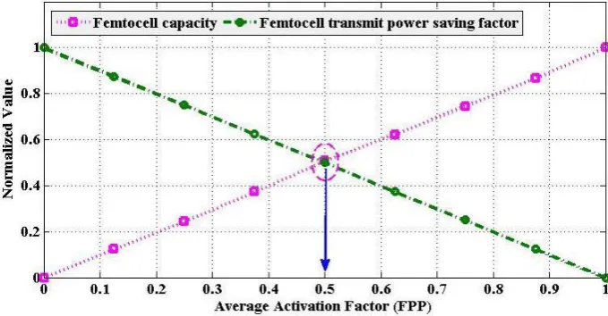
In Fig. 10, the transmit power saving response of the FCBS is shown. As expected, the transmit power saving decreases with an increase in AAF. This calls for a trade-off between the high capacity and the power saving demands of a FCBS. We address this issue by deriving an OAF in Eq. (27). As shown in Fig. 10, the OAF is about 0.5, which complies with the derived OAF in Eq. (27). Hence, an optimization of both the capacity and energy efficiency of FCBSs can be achieved when each FCBS has on an average an equal or near equal on-state and off-state durations subject to 1 2. In general, for12 1, the slope
[image:16.595.125.470.309.512.2]Fig. 9. Capacity of different categories of MUs with a variation in FBS.
Fig. 10. Femtocell capacity, transmit power saving factor, and OAF with a variation in AAF.
of capacity of the FCBS (Fig. 10) decreases, which results in an obvious increase in the value of OAF from 0.5 in order to compensate the capacity of the FCBS corresponding to the amount of decrease in slope from that ofFC,max.
Further, a FCBS can be considered serving neighboring on-state FCBSs during its normal off-state, which corresponds to its OAF
*, using JT CoMP to improve the network capacity only. In such case, a FCBS needs to operate in a CoMP set for duration greater than that corresponds to the OAF. However, if the energy efficiency is concerned only, a FCBS can operate for duration less than that corresponds to the OAF. In such case, no JT CoMP set is needed to form, and a FCBS can operate as a usual single entity. If both network capacity and energy efficiency are concerned, as mentioned already, a FCBS needs to operate for duration corresponds to the OAF.7.
Conclusion
In this paper, we propose a centralized 3D radio resources, namely time, frequency and power, allocation and scheduling strategy for a multi-tier control-/user-plane separation architecture (CUSA). Centralized scheduling is performed by considering schedulers of all BSs located at a central station acting as a hub for scheduling resources to all BSs. We propose a fully blank subframe (FBS) based eICIC to split completely C-/U-plane such that C-plane of all UEs can be served by the MCBS only, and U-plane of a UE by its respective BS. The cross-tier interference is avoided in time-domain, and the co-tier interference is avoided in frequency-domain by allocating frequency resources orthogonally in each tier.
The transmit power of any FCBSs is controlled by proposing a power control mechanism, modeled its on-state and off-state as conventional on/off traffic source model for single user per FCBS. However, for multiple user per FCBS, the transmit power of a FCBS is modeled as conventional Birth-Death process. We also derive an optimal value of average activation factor (OAF) over a FPP to trade-off capacity and power saving factor of any FCBSs to address both spectral and energy efficiency demands of 5G cellular. The performance evaluation is carried out with a multi-tier network that consists of a MCBS and a number outdoor PCBSs and indoor FCBSs deployed in a multi-storage building. The whole system bandwidth is reused in FCBSs within the building.
[image:17.595.127.467.108.285.2]lower than the OAF as a usual single entity if the energy efficiency needs to improve. This contribution will give operators insights on scheduling time, frequency, and power centrally particularly for SCs in CUSA in order to address the demands of the high indoor capacity and energy efficiency of future 5G mobile networks.
Acknowledgements
The initial results of this paper were presented partly in the conference article [30]. The research grant funds have been provided by “The 100th Anniversary Chulalongkorn University Fund for Doctoral
Scholarship” upon submission of application of research expenses for “The 90th Anniversary
Chulalongkorn University Fund (Ratchadaphiseksomphot Endowment Fund)” and “The Electrical Engineering Chulalongkorn University PhD (EECU-PhD) Honors Program Scholarship” at Chulalongkorn University, Bangkok, Thailand. The research is also graciously supported by the STAR Project, Department of Electrical Engineering, Chulalongkorn University, Thailand.
References
[1] H. T. Cheng and W. Zhuang, “Joint power-frequency-time resource allocation in clustered wireless mesh networks,” IEEE Netw., vol. 22, no. 1, pp. 45-51, Jan./Feb. 2008.
[2] L. Zhao, L. Cong, F. Liu, K. Yang, and H. Zhang, “Joint time-frequency-power resource allocation for low-medium-altitude platforms-based WiMAX networks,” IET Commun., vol. 5, no. 7, pp. 967-974, 2011.
[3] D. T. Ngo, S. Khakurel, and T. Le-Ngoc, “Joint subchannel assignment and power allocation for OFDMA femtocell networks,” IEEE Trans. Wireless Commun., vol. 13, no. 1, pp. 342-355, Jan. 2014. [4] M. Qian, Y. Wang, Y. Zhou, L. Tian, and J. Shi, “A super base station based centralized network
architecture for 5G mobile communication systems,” Digital Commun. & Netw., vol. 1, no. 2, pp. 152-159, 2015.
[5] China Mobile Research Institute, “C-RAN the road towards green RAN,” White Paper, ver. 2.5, Oct. 2011.
[6] Y. Lin, L. Shao, Z. Zho, Q. Wang, and R. K. Sabhiki, “Wireless network cloud: Architecture and system requirements,” IBM J. Research &Development, vol. 54, no. 1, pp. 4:1-4:12, Jan.-Feb. 2010. [7] Alcatel-Lucent, “LightRadio,” White Paper: Technical Overview, 2011.
[8] X. Duan, A. M. Akhtar, and X. Wang, “Software-defined networking-based resource management: data offloading with load balancing in 5G hetnet”, EURASIP J. Wireless Commun. & Netw., vol. 181, pp. 1-13, 2015.
[9] F. Zhang, S. Sun, N. Chen, and H. Huang, “Radio resource management based on NFV and SDN in 4G and 5G hetnet,” S. Sun and J. Li (Eds.) Self Organizing Networks, ICSON 2015, Lecture Notes of the Institute for Computer Sciences, Social Informatics and Telecommunications Engineering, Vol. 149, pp. 165-172, 2015.
[10] A. Prasad, A. Maeder, and C. Ng, “Energy efficient small cell activation mechanism for heterogeneous networks,” in Proc. Globecom Workshop-Heterogeneous and Small Cell Networks, 2013, pp. 754-759.
[11] C. Liu, B. Natarajan, and H. Xia, “Small cell base station sleep strategies for energy efficiency,” IEEE Trans. Veh. Technol., vol. 65, no. 3, pp. 1652-1661, Mar. 2016.
[12] G. Lee and H. Kim, “Green small cell operation using belief propagation in wireless networks,” in
Proc. Globecom Workshop-Heterogeneous and Small Cell Networks, 2014, pp. 1266-1271.
[13] R. K. Saha, P. Saengudomlert, and C. Aswakul, “Evolution toward 5G mobile networks - A survey on enabling technologies,” Engineering Journal, vol. 20, no. 1, pp. 87-119, 2016.
[14] R. K. Saha and C. Aswakul, “Incentive and architecture of multi-band enabled small cell and UE for up-/down-link and control-/user-plane splitting for 5G mobile networks,” Frequenz J. RF-Engineering & Telecommun., vol. 75, no. 1-2, pp. 95-118, Nov. 2016.
[16] A. Mohamed, O. Onireti, M. A. Imran, A. Imran, and R. Tafazolli, “Control-data separation architecture for cellular radio access networks: a survey and outlook,” IEEE Commun. Surveys & Tuts., vol. 18, no. 1, pp. 446-465, 2016.
[17] J. D. Chimeh, M. Hakkak, and S. A. Alavian, “Internet traffic and capacity evaluation in UMTS downlink,” in Proc. Future Generation Communication and Networking (FGCN), 2007, pp. 547-552.
[18] ETSI, “Universal mobile telecommunications system (UMTS); selection procedures for the choice of radio transmission technologies of the UMTS,” European Telecommunications Standards Institute (ETSI), TR 101 112,UMTS 30.03, ver. 3.2.0, 1998-2004.
[19] L. Kleinrock, Queueing Systems, Vol I: Theory. Wiley-Interscience, 1975.
[20] J. Perez-Romero, O. Sallent, R. Agusti, and M. A. Diaz-Guerra, Radio Resource Management Strategies in UMTS. Wiley, 2005.
[21] 3GPP, “Technical specification group radio access network; evolved universal terrestrial radio access (E-UTRA); FDD home eNodeB (HeNB) radio frequency (RF) requirements analysis (release 9),” 3rd
Generation Partnership Project (3GPP), TR 36.921, Ver. 2.0.0, Mar. 2010.
[22] J. Ellenbeck, J. Schmidt, U. Korger, and C. Hartmann, “A concept for efficient system-level simulations of OFDMA systems with proportional fair fast scheduling,” in Proc. IEEE GLOBECOM Workshops, 2009, pp. 1-6.
[23] Y. Wang, K. I. Pedersen, T. B. Sørensen, and P. E. Mogensen, “Carrier load balancing and packet scheduling for multi-carrier systems,” IEEE Trans. Wireless Commun., vol. 9, no. 5, pp. 1780-1789, 2010.
[24] H. J. Bang, T. Ekman, and D. Gesbert, “Channel predictive proportional fair scheduling,” IEEE Trans. Wireless Commun., vol. 7, no. 2, pp. 482-487, 2008.
[25] 3GPP, “Simulation assumptions and parameters for FDD HeNB RF requirements,” 3rd Generation
Partnership Project (3GPP) TSG RAN WG4 (Radio) Meeting #51, R4-092042, May 2009.
[26] 3GPP, “Evolved universal terrestrial radio access (E-UTRA); radio frequency (RF) system scenarios,” 3rd Generation Partnership Project (3GPP), TR 36.942, ver. 1.2.0, Jul. 2007.
[27] R. K. Saha and P. Saengudomlert, “Novel resource scheduling for spectral efficiency in LTE-Advanced systems with macrocells and femtocells,” In Proc. International Conference on Electrical Engineering/Electronics, Computer, Telecommunications and Information Technology(ECTI-CON), pp. 340-343, 2011.
[28] R. K. Saha and C. Aswakul, “A tractable analytical model for interference characterization and minimum distance enforcement to reuse resources in three-dimensional in-building dense small cell networks,” Int. J. Commun. Sys.,(early view) pp. e3240, 2017, doi: 10.1002/dac.3240
[29] R. K. Saha, “Modified proportional fair scheduling for resource reuse and interference coordination in two-tier LTE-Advanced systems,” Int. J. Digital Info.& Wireless Commun., vol. 3, no. 2, pp. 9-28, Jul. 2013.
[30] R. K. Saha and C. Aswakul, “Centralized 3D radio resource allocation and scheduling for multi-tier control-/user-plane split architecture for 5G mobile network,” in Proc. 2017 International Conference on
Electronics, Information, and Communication (ICEIC), (to appear in IEEE Xplore), Phuket, Thailand, 11-14