DYNAMIC ANALYSIS OF A LIGHTWEIGHT CLUTCH DISC
ZA WEER AKRAM BIN ZAINAL ABIDEN
This report is submitted in accordance with requirement for the Bachelor of Mechanical Engineering (Automotive)
Faculty of Mechanical Engineering Universiti Teknikal Malaysia Melaka
. l MAY 2012
SUPERVISOR DECLARATION
'I admit that had read this thesis and in my opinion this thesis was satisfied from the aspect of scope and quality for the purpose to be awarded
Bachelor of Mechanical Engineering (Automotive)'
Signature
Name of Supervisor
Date
©
Unlverlltl Teknlkal Malaysia Melalali
• •••• !'-r! ••••••••••••••••••••••••DECLARATION
"I verify that this report is my own work except for the citation and quotation that the source has been clarified for each one of them"'
Signature
Name of Author Date
.
10
©
Unlverlltl Teknlkal Malaysia MelalalIll
To my father, Zainal Abiden bin Sayadi, my mother, Zauyah binti Abd Hamid, my siblings, my friends and my supervisor, Encik Fudhail bin Abdul Munir, for supporting me throughout
this project and for their understanding in the way I am.
iv
ACKNOWLEDGEMENT
First, I want to express my gratitude to Allah S. W. T for hjs blessings and guidance that I was able to complete the fmal year project report successfully. I would like to express my sincere appreciation to Encik Fudhail Bin Munir for his insight and guidance. It is being a big opportunity to work and learn under your supervision. He enlightens me not only on academic researchbut also on personal life. I would also like to thank Encik Mohd Adrinata Bin Shaharuzaman and Encik Mohd Rody Bin Mohamad Zin for their careful exammation on this dissertation and for very helpful comments. Thanks also go to my other colleagues; their friendship is eternal treasure for me. I thank all members, sister and brother. Without their continuous love, I would not have the courage to purse a degree. Special thanks to my parents who have already sacrificed a lot of support me through this period of my study.
v
ABSTRACT
The name of clutch has become established due to its meaning of grasp or grip tight. The clutch has the function to enable one rotary drive shaft to be coupled to another shaft,
either when the both shaft are stationary or when there is relative motion between them.
In this project, we are focusing on the designing of dry clutch disc by using software of Computer Aided Drafting (CAD) that is CA TIA V5. The method that arc we will go through of the designing in engineering which consist of research, observation, application of theory and justifying the result obtained and also analysis process. The designed parts are compatible and efficient with a companion parts.
In this study, both fmite element analysis are conducted to explore the effects of design parameters on the slipping torque of lightweight clutch. Modeling by the Finite Element Model (FEM) which can result from the choice of numerical parameters such as:
symmetry conditions, contact parameters, convergence parameters or mesh density. This dynamic analysis can be done using software of Finite Element Analysis (FEA) that is ANSYS.
It is found out in this study that the maximum shear stress value is 3.9109e5 Pa for spindle part, meanwhile the disc composition maximum shear stress is 1.0853e5 Pa. The total deformation value for spindle part is 6.8442e-7m and for disc composition is 6.063Se-7m.
TABLE OF CONTENT
CHAPTER TITLE
DECLARATION
DEDICATION
ACKNOWLEDGEMENT
ABSTRACT
TABLE OF CONTENT
LIST OF TABLE
LIST OF FIGURE
LIST OF SYMBOL
LIST OF APPENDIX
1.0 INTRODUCTION
1. 1 Background
1.2 Objectives
1.3 Scopes
1.4 Problem Statement
2.0
LITERATURE REVIEW2.1 Overview of Clutch
2.1.1 History of Clutch Disc Development
2.1.2 Lightweight Clutch Disc
©
Unlverlltl Teknlkal Malaysia MelalalPAGE 11 111 IV v Vl X XI
X Ill
vii
CHAPTER TITLE PAGE
2.2
Disc Clutch6
2.2.1
Type of clutch disc 92
.
3
Components of Disc Clutch10
2
.
3.1
Pressure Plate10
2.3.2
Flywheel 112
.
3
.
3
Release Bearing12
2
.
3.4
Clutch Housing13
2.
3
.5
Clutch Fork13
2
.
3
.
6
Clutch Adjustment14
2.4
Automotive Clutch Mechanism16
2.4
.
1
Mechanically Clutch Control Mechanism16
2.4
.
2
Hydraulically Operated Clutch Arrangement17
3.0
METHODOLOGY18
3.1
Designing the Clutch Disc18
3.1.1
Analysis Clutch Disc Design20
3.1.2
Dimension of Clutch Disc22
3.2
Material Selection23
viii
CHAPTER TITLE PAGE
3.2.1
Carbon-carbon Composite23
3.2.2
Properties of Carbon-carbon Composite24
3.3 Meshing
25
3.4 Finite Element Analysis
26
3.5
Software of Finite Element Analysis27
3.5.1
Dynamic Stress Analysis28
3.6
Boundary Condition29
4.0 RESULT AND DISCUSSION
31
4.1
Calculation31
4.1.1
Calculating the Shear Stress, r31
4.1.2
Calculation ofTotal Deformation, E33
4.2
Static Structural35
4
.
3
Shear stress37
4.3.1
Shear Stress for Spindle Part37
4.3.2
Shear Stress for Disc Composition Part38
CHAPTER TITLE
4.4 Total Deformation
4.4.1 Total Deformation for Spindle Part
PAGE
39
39
4.4.2 Total Deformation for Disc Composition Part 40
5.0 CONCLUSION AND RECOMMENDATION
5.1 Conclusion
5.2 Reconunendation
REFERENCES
APPENDICES
©
Unlverlltl Teknlkal Malaysia Melalal41
41
44
45
48
NO.
3.1
3.2
5.1
5.2
LIST OF TABLE
TITLE PAGE
Dimension of the clutch disc
Properties of Carbon-carbon Composite
Results of Static Structural Analysis for Spindle part
Results of Static Structural Analysis for Disc Composition part 22
24
42
43
©
Unlverlltl Teknlkal Malaysia Mellllalxi
LIST OF FIGURE
NO. TITLE PAGE
2.1 View ofthe clutch
7
2.2 Detailed design of the clutch disc
8
2
.
3
Cushion Disc9
2.4
Pressure Plate11
2
.5
Flywheel12
2.6
Release Bearing12
2
.
7
Clutch Housing13
2.8
Clutch Fork14
2
.
9
Clutch adjustment and Linkage15
3
.1
Clutch Design19
3.2
Disc and spindle part20
3
.3
Disc, mid disc and pressure plate21
3.4
Named of Geometry22
3.
5
Meshing for both parts25
3
.
6
Boundary Condition for spindle part29
3
.
7
Boundary Condition for Disc composition part30
4.1
Apply Torque and Fix support for spindle part35
4
.
2
Apply Torque and Fix support for disc composition part36
4
.
3
Isometric view Shear Stress for spindle part37
4.4
Isometric view Shear Stress for disc composition part38
4.5
4.6
Isometric view total deformation for spindle part
Isometric view total deformation for disc composition part
©
Unlverlltl Teknlkal Malaysia Melalal39
40
xiii
LIST OF SYMBOL
T
=
torque transmitted, NmPmax maximum pressure applied onto the clutch, Pa
F force act
ro
=
outer radius, mri
=
inner radius, mDi
=
inner diameter of the clutch, mDo
=
outer diameter of the clutch, m() stress (Yield Strength)
E
=
modulus of elasticity (Young's Modulus)£ strain
= change in length (deformation)
L
=
original length (thickness of clutch disc)T shear stress
J
polar moment of inertia (hollow shaft)A area of part.
xiv
LIST OF APPENDIX
NO. TITLE PAGE
A Flow Chart
48
B Gantt Chart 49
c
Clutch Disc (benchmark) 50D Clutch Disc (inCA TIA V5) 51
E Clutch Drafting 52
F Clutch isometric view 53
G Shear Stress Spindle 54
H Shear Stress Disc Composition 55
Total Deformation Spindle 56
J Total deformation Disc Composition 57
1
CHAPTER 1
INTRODUCTION
1.1 Background
A clutch is a mechanical device, by convention understood to be rotating,
which provides driving force to another mechanism when required, typically by
connecting the driven mechanism to the driving mechanism. The name of clutch has
become established due to its meaning of grasp or grip tight (Heinz Heisler, 1999).
Clutches are useful in devices that have two rotating shafts. ln these devices,
one shaft is typically attached to a motor or other power unit (the driving member),
and the other shaft (the driven member) provides output power for work to be done.
The clutch connects the two shafts so that they can either be locked together and spin
at the same speed (engaged), or be decoupled and spin at different speeds
(disengaged).
2
Dry clutch are widely used on large trucks and heavy industrial units. The
main advantages of dry clutch are its large contact area and the main components of
a dry disc clutch are pressure plate and the disc.
1.2 Objective
The objectives of this project are:
1. To design a lightweight dry clutch disc
2. To study dynamic analysis for lightweight dry clutch disc using CAE
software.
3. To investigate the behavior of lightweight clutch disc under axial force.
1.3 Scopes
The scopes of study for this project are:
I. To generate 3-dimensional geometry model of a lightweight clutch disc by using CATIA V5Rl2.
2. To study the dynamic stress of a lightweight clutch for capacity under the
torque of 150Nm.
3. Simulation analysis will be done by ANSYS 12.1 or ABAqus 6.9.
3
1.4 Problem Statement
This project will enable me to understand more about the clutch disc of a
vehicle. As we know clutch system are crucial in the performance of a vehicle. Due
to the project we will investigate the performance of vehicle by doing the dynamic
analysis on the clutch disc.
Nowadays, lightweight disc clutch is an essential part for vehicle. The lighter
the overall weight, the higher the fuel efficiency will be. Apart from that, the light
clutch enables the manoeuvre without the feel of high contact pressure, it is driver
friendly. There are not many references that can be obtained pertaining to methods
need to be employed in order to design a proper clutch disc. The resources are very
limited. Therefore, a reverse engineering for a design need to be done, this method
are mostly base on a real model of clutch disc that available in market. Therefore, by
embarking into this project, the methods to design a clutch disc can be acquired.
Then, dynamic analysis will be conducted onto the designed disc to investigate the
parameter that affected the performance of the clutch disc.
By reducing weight are able to reduce fuel consumption and enhance the
performance that can be obtained and knowing how to design clutch disc, we are able
to manipulate the parameters involves to improve the design feasibilities.
4
CHAPTER2
LITERATURE REVIEW
2.1 Overview of Clutches
A clutch is a mechanical device for quickly and easily connecting or
disconnecting a pair of rotating coaxial shafts. It is usually placed between the
driving motor and the input shaft to a machine, permitting the engine to be started in
an unloaded state. Single plate, dry clutch is among the popular type of clutches in
use (Lee and Cho 2006). Mechanical clutches fall into two main categories: positive
engagement and progressive engagement. (Garret et al. 200 1 ).
2.1.1 History of Clutch Disc Development
In 1885, it was reported that when Karl Friedrich Benz has invented the first
commercial gas powered automobile, the famous Tri-Cycle, he also was the first
person to invent and use the clutch system to the car (Wikipedia website 2007).
Exedy Corp., one of the major players for clutch technology, which manufactured clutches under the brand name of Exedy and Daikin, was reported to produce rigid
type disc clutch since 1918, which was a clutch disc with the plate and spline hub
5
secured by rivets (Daikin Clutch website 2007). Until now, clutch manufactures has
come out with new and efficient technologies for clutch system to compensate higher
torque produced by bigger engine created especially for heavy vehicles.
2.1.2 Lightweight Clutch Disc
The heaviest components of the clutch system are the clutch cover, plates and
flywheel. Full Carbon clutches utilize carbon clutch and intermediate achieving a
reduction in total weight. Semi-Carbon clutches incorporate an improved cover
configuration and lightened flywheel also enabling a reduction in vehicle weight. In
1995 Exedy supplied Carbon clutch products for use in the pinnacle series of motor
sport, Formula One. This same technology is now applied to Carbon clutches
developed by Exedy for use in various forms of motor-sport providing an explosive
shift feeling and dramatic improvement in engine response. ·(www.exedy
racing.com.). The carbon material exhibits a low density, excellent heat and wears
resistance, high mechanical strength and excellent dimension stability. (www.
sicom-brake.com).
The common materials for clutch disc are asbestos. Asbestos is nearly an
ideal friction material for brake lining and clutch facing because it has a very good
coefficient of friction, excellent heat characteristics, and low cost (Thomas Birch,
1999). However, it has the possibility to cause cancer from inhaling its fibers. Due to
this, the use of asbestos has been decreased significantly. Asbestos has been replaced
with fiberglass and aramid nonmetallic compounds and metalJic friction facings
using various mixtures of powdered iron, copper, graphite, and ceramics to obtain the
desired friction and wear characteristics.
Some clutches use a ceramic material of clay and metal. Frequently a
composite metallic friction material or a cellular paper material is used. These
materials have good durability and friction capacity in oil. However, ceramics have
several disadvantages. Firstly, it is difficult to be manufactured and secondly is
ceramics can cause the mated pairs to wear excessively.
6
2.2 DISC CLUTCH
Disc clutch can be either dry or wet. Dry here means the clutch operates in
dry condition. On the other hand, wet here means, the clutch operates in oil bath or
spray. Dry clutch are widely used on large trucks and heavy industrial units. The
main advantage is it large contact area. However, dry clutch are not recommended to
be used in condition where frequent disengaging or slipping is required due to the
heat build up (Donald etc al. 1974). Wet clutch are actuated either mechanically or
hydraulically. Operation in oil reduces wear and provides cooler operation. The
major difference between the dry and the wet clutch is that the disc facing material.
In a wet clutch, this material must grip when soaked in oil.
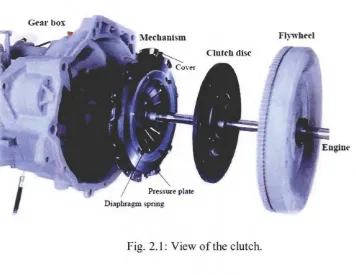
Today's passenger cars and light trucks are now almost exclusively equipped
with conventional friction clutches (i.e. diaphragm spring clutches). In this work,
We only consider dry friction clutches. It is composed of the clutch disc, the
flywheel, and the mechanism, which is itself composed of a cover, a diaphragm
spring, and a pressure plate (Fig. 2.1). When the engine rotates freely (no gear
engaged) no torque is transmitted because the clutch disc is not in contact with the
mechanism and rotates freely (Fig. 2.1 ). When a gear is engaged, the clutch disc is
compressed by the diaphragm spring between the pressure plate of the mechanism
and the flywheel transmitting the rotary motion and the torque to the mechanism and
thus to the wheels.
7
Fig. 2.1: View of the clutch.
The clutch disc is crushed between the mechanism pressure plate and the flywheel to
transmit the torque from the combustion engine to the transmission. The necessity of
coupling or decoupling the engine and transmission during gearshift induced the
development of optimized clutch components that aim to transmit the torque between
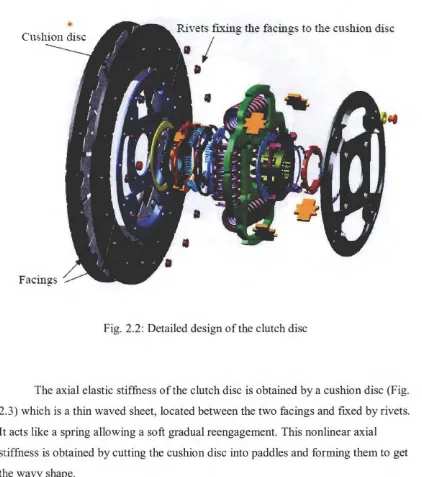
the pressure plate and the flywheel. In this work, we investigate the behavior of the
clutch disc (Fig. 2.2). It allows a soft gradual re-engagement of torque transmission.
This progressive re-engagement obtained by the clutch disc characteristics in the
axial direction preserves the driver's comfort and avoids mechanical shocks. It also plays the role of a damper through the springs disposed around the hub. They enable
the clutch disc to filter the torque variations of the combustion engine (Fig. 2.2).
[image:22.557.98.454.61.336.2]8
• RiYets fL"X.ing the facings to the cushion disc
• I
•
Facings
Fig. 2.2: Detailed design of the clutch disc
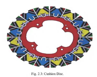
The axial elastic stiffness of the clutch disc is obtained by a cushion disc (Fig.
2.3) which is a thin waved sheet, located between the two facings and fixed by rivets.
It acts like a spring allowing a soft gradual reengagement. This nonlinear axial
stiffness is obtained by cutting the cushion disc into paddles and forming them to get
the wavy shape.
[image:23.557.87.509.63.540.2]9
Fig. 2.3: Cushion Disc.
2.2.1 Type of clutch disc
The name of clutch has become established due to its meaning of grasp or
grip tight. The clutch has the function to enable one rotary drive shaft to be coupled
to another shaft, either when the both shaft are stationary or when there is relative
motion between them (Heinz Heisler, 1999). The need for the clutch stems is mainly
from the characteristics of the turning effort developed by the engine over its lower
speed range. When idling, the engine develops insufficient torque for the
transmission to be positively engaged. The engine speed has to be increased before
complete coupling without slip may be made. Basically, in agricultural machinery,
there are three main clutches that normally used. These clutches are disc clutch, cone
clutch, and overrunning clutch (Donald etc. al. 1974). All these types of clutches
come under axial friction clutches (Sand.hu, 2001 ).
[image:24.557.128.462.53.318.2]