MODELLING AND SIMULATION OF DISC BRAKE CONTACT ANALYSIS AND SQUEAL
A. R. A. Bakar1, H. Ouyang2, D.Titeica3 and M.K.A. Hamid1 1
Department of Aeronautic and Automotive Technology Universiti Teknologi Malaysia
81310 UTM Skudai 2
Department of Engineering University of Liverpool
Brownlow Street L69 3GH , Liverpool
United Kingdom 3
Sensor Product Inc 188 Route 10, Suite 307
East Hanover NJ 07936-2108, USA
ABSTRACT
Predicting disc brake squeal by means of the complex eigenvalue method has been a popular approach in the brake research community owing to its advantages over the dynamic transient method. The positive real parts of the complex eigenvalue reflect the degree of instability of the brake system and are thought to indicate the likelihood of squeal occurrence. This paper studies the disc brake squeal using a detailed 3-dimensional finite element (FE) model of a real disc brake. A number of structural modifications for suppressing unstable vibration are simulated. Influence of contact pressure distribution on squeal propensity is also investigated. A plausible modification that results in reduced positive real parts of the eigenvalues is proposed.
Keywords: disc brake; contact analysis; complex eigenvalue; squeal; structural modifications INTRODUCTION
Nowadays, passenger cars become one of the main transportation for people travelling from one place to another. Thus, comfort issues of the passenger cars should a major concern. One of vehicle components that occasionally generate unwanted noise and vibration is the disc brake system. As a result, carmakers, brake system and friction material suppliers face challenging tasks to reduce high
warranty payouts. Akay (2002) stated that the warranty claims due to the brake noise, vibration and harshness (NVH) including brake squeal in North America alone were up to one billion dollars each year. Furthermore, Abendroth and Wernitz (2000) noted that many friction material suppliers had to spend up to 50 percent of their engineering budgets on the NVH issues.
The brake noise and vibration phenomena can be described based on the mechanism of generation. Disc brake noise and vibration can be divided into three categories, i.e. creep-groan, judder and squeal (Ouyang et al. 2003). The most troublesome and annoying noise is squeal, which is an irritant to both car passengers and the environment, and expensive to the brake and the car manufacturers in terms of warranty costs (Crolla et al. 1991). Brake squeal is defined as a friction induced vibration and it generally occurs at frequencies above 1kHz.
In recent years, finite element method becomes the most popular tool in studying disc brake squeal (Ripin 1995; Tirovic and Day 1991; Abu bakar and Ouyang 2004; Mahajan et al. 1999). This is owing to the fact that experimental methods could not predict any squeal at early design stage. In addition, the finite element method is capable of simulating any changes made on the disc brake components much faster and easier than experimental methods. In order to predict the onset of squeal most researchers prefer the complex eigenvalue analysis. Discussions on such analysis in comparison with other analyses are given in details in references (Ouyang et al. 2003; Mahajan et al. 1999). The essence of the complex eigenvalue method lies in the inclusion of the asymmetric friction stiffness matrix that may be derived from contact pressure analysis. The positive real parts of the complex eigenvalues reflect the degree of instability of the (linearised) brake system and are thought to indicate the likelihood of squeal occurrence.
The contact pressure distribution in disc brakes has been investigated by a number of people. However, to date, measuring dynamic contact pressure distribution remains impossible. Tumbrink (1989) attempted to measure static pressure distribution using a ball pressure method. Contact pressure prediction by means of numerical method was studied in (Ripin 1995; Tirovic and Day 1991; Abu bakar and Ouyang 2004). There are various models of different degrees of sophistication to predict contact pressure through numerical methods. Figure 1 shows the static contact pressure distribution for a typical disc brake using a sensitive pressure film.
FIGURE 1 Contact Pressure Distribution: Topography on Sensitive Pressure Film (left) and Analysed Image (right)
FINITE ELEMENT MODEL
The finite element model of a disc brake of floating caliper design consists of a solid disc, a caliper, a carrier bracket, a piston, two pads and two guide pins as illustrated in Fig. 2. There are about 8000 solid elements and a total of approximately 70,000 degrees of freedom (DOFs) in the model. Validation of the disc brake components is the first step towards a valid assembly model. A good correlation at the assembly level between FE prediction and experimental result is crucial to accurately predict the onset of squeal using the complex eigenvalue analysis.
FIGURE 2 Finite Element Model of the Disc Brake
Modal analysis was normally carried out to validate components and assembly model. Table 1 and Table 2 show the validation results of the disc and assembly model, respectively. It is shown that FE predictions agree well with the experimental results.
TABLE 1 Modal result of the solid disc at free-free condition
Mode 2ND* 3ND 4ND 5ND 6ND 7ND
Test (Hz) 937 1809 2942 4371 6064 7961
FEA (Hz) 944 1819 2942 4357 6029 7922
Error (%) 0.8 0.6 0.0 -0.3 -0.6 -0.5
ND* stand for Nodal Diameters
TABLE 2 Modal result of the assembly model measured on the disc
Mode 2ND 3ND 3ND 4ND 5ND 6ND 7ND
Test (Hz) 1287.2 1750.7 2154.9 2980.4 4543.7 6159.0 7970.0 FE (Hz) 1295.9 1713.9 2193.2 3044.7 4535.1 6077.9 8050.0
Error (%) 0.7 -2.1 1.8 2.2 -0.2 -1.3 1.0
COMPLEX EIGENVALUE ANALYSIS
)
=In general, the eigenvalue problem of the finite element model is given by
(
2 MN MN MN N 0 (1)M C K
λ
+λ
+φ
where λ is the eigenvalues, MMN is the mass matrix, CMN is the damping matrix,KMN is the stiffness matrix ( for the case of disc brake squeal, initial stress and friction effects are included and therefore generate unsymmetrical matrix), φN is the eigenvectors (mode of vibration). Both eigenvalues and eigenvectors can be complex.
Four different pressures and rotational speeds of the baseline model are examined. Table 3 shows squeal frequencies generated in the experiment. Squeal prediction by finite element model is illustrated in Fig. 3. The prediction shows more unstable frequencies and this is simply due to neglect of the components’ material damping. Nevertheless, there is good agreement between FE calculations and experimental results. The predicted contact pressure distributions about centerline of the pad are depicted in Fig. 4.
TABLE 3 Squeal Frequencies Generated in the Experiment
Operating Conditions Mode Squeal
Pressure (MPa) Speed (rad/s) Nodal Diameter Frequency (Hz)
0.16 26.0 4 2944.4
0.16 26.0 6 6797.1
0.22 6.3 5 4275.1
0.34 3.2 3 1755.6
0.83 6.3 7 7540.2
FIGURE 3 Prediction of Unstable Frequencies at Different Pressure
and Disc Speeds of Baseline Model
FIGURE 4 Contact Pressure Distribution at Piston Pad (left) and Finger Pad (right). Right Hand Side of the Diagram is the Leading Edge of the Pad.
STRUCTURAL MODIFICATIONS
Generally, structural (including material) modifications are a favourite means of improving squeal performance of the disc brake. In this paper, several structural modifications are carried out and they are explained in Table 4. Figure 5 shows predicted unstable frequencies of modified structures and material at pressure of 0.83MPa and speed of 6.3rad/s. It is shown that M1, M4 and M5 do not make any improvement since they generated the same unstable frequencies as obtained in the baseline model. While M3, M1+M2 and M2+M4 are not favourable modifications since more unstable frequencies are generated than the baseline model. These modifications generated more unstable frequencies above 7000Hz as shown in Fig. 5. By removing some spring elements at certain location between the piston and the piston-pad back plate, and the finger and the finger-pad back plate (M2), unstable frequencies above 6000Hz are eliminated, however, most of the unstable frequencies remain below this frequency. Thus, this is not a favourable modification either. Combining M2 with M3 and M5 seems to be a promising solution as most of the unstable frequencies are eliminated except one at frequency 8600Hz. Therefore, the authors regarded this modification as a plausible one. Now, it is interesting to see the distributions of contact pressure of these modifications. The contact pressure distributions at the piston and finger pad are shown in Fig. 6.
TABLE 4 Structural and Material Modifications
No Modifications Descriptions
1 Baseline Unmodified
2 Slotted pad (M1) Centre of the pad
3 Finger & piston partial connection (M2) See Fig. 7
4 Stiffer disc (M3) E=150GPa
5 Vented disc (M4) 22 slots
6 Stiffer calliper (M5) E=700GPa
7 M1+M2
8 M2+M4
9 M2+M3+M5
FIGURE 5 Unstable Frequencies of Modified Structures and Material
FIGURE 6 Contact Pressure Distribution of Structural Modifications at Piston
Pad (left) and Finger Pad (right)
For the piston pad, M1, M4 and M5 follow exactly the trend of the baseline model whilst M3 almost produced the same magnitude of the baseline model except in the middle of the pad, where the pressure fluctuated mildly due to the presence of the slot. The rest of the modifications produced slightly different results, where the contact pressure is much higher at the trailing edge and slightly lower at the leading edge, than those of the baseline model. Fluctuation also occurred in the middle of the pad for M1+M2. For the finger pad, M1, M3, M4 and M5 lead to exactly the same trend of the baseline model whilst the rest produced slightly higher contact pressure at the trailing edge.
a) Piston Pad b) Finger Pad
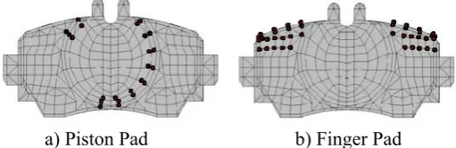
FIGURE 7 Partial Connections in the Axial Direction (the Red Dot Represents Removal of One Axial Connection)
Comparison of different structural modifications in terms of the respective contact pressure distribution at the piston and the finger pads and the unstable frequencies obtained previously seems to suggest that a favourable contact
pressure distribution alone is not good enough to suppress the occurrence of squeal. It can be seen that even though M2 produces almost the same magnitude of the contact pressure of M2+M3, the resultant unstable frequencies are different. The reason M2+M3+M5 eliminates most of the unstable frequencies below 8000Hz is due to mode decoupling between and/or within the pad, the disc and the caliper (Kung 2000) .
CONCLUSIONS
This paper studies the influence of contact pressure distributions on the squeal occurrence as a result of structural modifications. Prior to the complex eigen value analysis finite element model of a real disc brake was validated through modal analysis, where good correlations are obtained at components and assembly level. There is also good agreement in squeal predictions between the FE model and experimental results. Several structural modifications are simulated. From the results, it is suggested that combined modification, i.e. partial connection and stiffer disc can eliminate unstable frequencies below 8000Hz, which are dominant in the baseline model. Therefore this modification is regarded as a plausible one. From the contact pressure point of view it seems that shifting the pressure towards the trailing edge alone is insufficient to suppress unstable frequencies. Mode-decoupling between and/or within the components stated aforementioned is believed to be another factor in eliminating unstable frequencies below 8000Hz.
ACKNOWLEDGEMENTS
The authors would like to thank the following for their contributions and supports: Dr S James (University of Liverpool), Dr Q Cao (University of Aberdeen), TRW Automotive, Sensor Products Inc. and the Government of Malaysia.
REFERENCES
Akay, A. 2002. Acoustic of friction, Journal of Acoustical Society of America, 111 (4) : 1525-1548.
Abendroth, H. and Wernitz, B. 2000. The integrated test concept dyno-vehicle; performance and noise, SAE Technical Paper, 2000-01-2774.
Ouyang, H., Nack, W., Yuan, Y. and Chen, F. 2003. On automotive disc brake squeal Part II: Simulation and Analysis, SAE Technical Paper, 2003-01-0684.
Crolla, D.A. and Lang, A.M. 1991. Brake noise and vibration- the state of the art, Vehicle Tribology (18), Leeds: 165-174.
Ripin, Z.B.M. 1995. Analysis of disc brake squeal using the finite element method, PhD Thesis, University of Leeds.
Tirovic, M. and Day, A.J. 1991. Disc brake interface pressure distributions, Proceedings of ImechE, Part D (205): 137-146
Abu Bakar, A.R. and Ouyang, H. 2004. Contact pressure distributions by simulated structural modifications, Proceedings of Braking 2004: Vehicle Braking and Chassis Control: 123-132.
Mahajan, S.K., Yu,Y. and Zhang, K. 1999. Vehicle disc brake squeal simulation and experiences, SAE Technical Paper, 1999-01-1738.
Tumbrink, H.J. 1989. Measurement of load distribution on disc brake pads and optimization of disc brakes using the ball pressure method, SAE Technical Paper, 890863.
ABAQUS Analysis User’s Manual Version 6.4, 2003
Kung, S.W., Dunlap, K.B. and Ballinger, R.S. 2000. Complex eigenvalues analysis for reducing low frequency brake squeal, SAE Technical Paper, 2000-01-0444.