International Journal of Innovative Technology and Exploring Engineering (IJITEE) ISSN: 2278-3075, Volume-8 Issue-8 June, 2019
Abstract: This paper exhibits an investigation on various cold formed steel channel sections which are placed Back-to-Back and Face-to-Face column members. The thickness of cold formed steel is confined to 3mm. A methodological investigation of uniaxial compression was performed numerically and experimentally. For this purpose, a total of four back-to-back channel sections and four face-to-face channel sections are assessed numerically using ANSYS 18.2 workbench. Breaking down the results of numerical investigation, three sections have demonstrated promising outcomes in carrying up the uniaxial load. Due to the clear evidence obtained in the test that three different sections show higher load carrying capacity and henceforth recommended for experimental investigation. Experimental tests are carried upon the chosen sections with a uniaxial load supported using pin-ended joints. The finite element model made utilizing numerical analysis demonstrates great concurrence with the test results. Using the experimental results and numerical results it is shown that the chosen sections provide better load carrying capacity. Inference of the results show that the section FF200-S0-C20- 3 takes up higher load carrying capacity of about 1.73 times the basic back-to-back channel section, which is viewed as better among the remainder of sections. Local buckling is the kind of failure accomplished when the section gets pass the ultimate strength.
Keywords: Cold Formed Steel, Compression, Buckling behaviour, Channel sections.
I. INTRODUCTION
A. General
Cold-formed steel (CFS) elements have predominantly been operated as secondary load carrying members in a wide range of applications such as purlins for roof, wall girts and cladding. In latest trend CFS elements are also increasingly being used as primary structural members, especially in low-to-mid rise multi-storey buildings. Compared to their hot-rolled counterparts, CFS individuals can potentially give increasingly economical and effective structure arrangements because of several advantages, for example, a light weight, a high flexibility in obtaining various cross-sectional shapes. however, as a result of the nature of the manufacturing process, CFS components are limited in wall thickness (usually less than 6-8 mm), which makes them more
Revised Manuscript Received on June 8, 2019
Praveen Kumar S, M.E. in Structural Engineering from SRM Valliammai Engineering College, Kattankulathur, Tamil Nadu, India.
Suresh Babu S, Assistant Professor, Department of Civil Engineering, SRM Valliammai Engineering College, Kattankulathur, Tamil Nadu, India
vulnerable to local, distortion and global buckling as well as their interactions. In this paper, the analytical results of eight new finite element tests on back-to-back and face-to-face built-up cold formed steel section, with the sections acting as columns. These eight different sections have been built-up in different ways and one of a kind. Gapped sections are being introduced with bolted connection in steel trusses and columns in portal frames, increasing the lateral stability of such columns. Analysing the results, three different sections are being chosen for which the ultimate strength is higher compared with the rest of the sections. The results of finite element analysis and experimental tests are being compared to check the efficiency of the section.
B. Specimen geometry
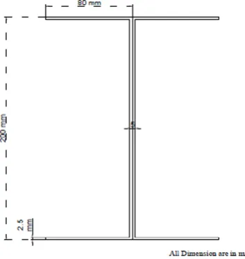
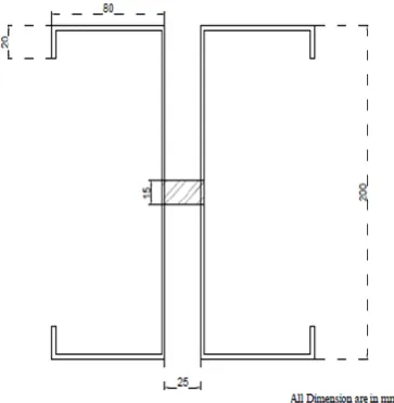
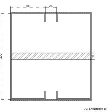
This paper exhibits the comparative study of eight contrary cold formed steel (CFS) sections by performing finite element analysis and experimental analysis. Indian Standard codal provisions IS 811: 1987 Cold Formed Light Gauge Structural Steel Section recommends different sections which can be used as load carrying members. Fig. 1-8 shows the
[image:1.595.335.512.504.691.2]cross-section details of various sections which are being used in this paper. Channel sections are being arranged in various positions as shown in Fig. 1-8.
Fig. 1 cross-section of BB200-S0-C0- 1
Performance Evaluation on Compressive
Behaviour of Contrary Cold Formed Steel
Sections
Fig. 2 Cross-section of GBB200-S25-C0- 2
Fig. 3 Cross-Section of BB200-S0-C20- 3
[image:2.595.70.249.51.237.2]Fig. 4 Cross-Section of GBB200-S25-C20- 4
[image:2.595.327.502.75.258.2]Fig. 5 Cross-Section of FF200-S0-C0- 1
Fig. 6 Cross-Section of GFF200-S25-C0- 2
[image:2.595.76.258.508.694.2]International Journal of Innovative Technology and Exploring Engineering (IJITEE) ISSN: 2278-3075, Volume-8 Issue-8 June, 2019
Fig. 8 Cross-Section of GFF200-S25-C20- 4
C. Sectional Naming
The sections were named such that the kind of section, spacing between two channel sections, width of lip and specimen no. were indicated by the label. Fig. 9 presents the naming of the section “BB200-S0-C20- 3” are detailed as follows:
“BB200” indicates back-to-back built-up channels with 200mm web depth.
“S0” indicates the distance between two channel sections
“C20” indicates the width of the lip section.
“3” indicates the specimen number as 3.
Fig.9 Sectional Naming
Table 1a)
Measured specimen dimensions for built-up back-to-back channel sections
Specimen Web Flange Lip Length Spacing between sections
A’ B’ C’ L S
(mm) (mm) (mm) (mm) (mm)
BB200-S0-C0- 1 200 80 0 1000 0
GBB200-S25-C0- 2 200 80 0 1000 25
BB200-S0-C20- 3 200 80 20 1000 0
GBB200-S25-C20- 4 200 80 20 1000 25
b) Measured specimen dimensions for built-up face-to-face channel sections
Specimen Web Flange Lip Length Spacing between sections
A’ B’ C’ L S
(mm) (mm) (mm) (mm) (mm)
FF200-S0-C0- 1 200 80 0 1000 0
GFF200-S25-C0- 2 200 80 0 1000 25
FF200-S0-C20- 3 200 80 20 1000 0
GFF200-S25-C20- 4 200 80 20 1000 25
II.NUMERICALSTUDY A. General
A finite element model is being created using ANSYS workbench. The model is being created using the cross-sectional dimensions from table1.
The total geometry was demonstrated for all the different sections as portrayed before. The connection between two specimens or sections are given utilizing bonded connections. Gapped sections are connected each other utilizing bolted connections. Uniaxial load was connected on to the example through its Centre of Gravity (CG). The segments were loaded from the top and checked for its compressive behaviour.
C. Geometry & Material
ANSYS 18.2 examination programming is being utilized to display the entire geometry of the developed sections. The Yield quality of the material is 280MPa and rigidity is 410Mpa which are gotten from Indian Standards IS 513: 2008 Cold Reduced Low Carbon Steel Sheets and Strips.
D. Meshing
The sections are modelled using ANSYS software. Tetrahedron mesh is being added to the model whose mesh size is 0.1m
E. Support and Load
Axial load is provided on the top of the specimen through the centre of gravity.
F. Analytical result
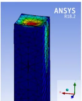
[image:4.595.356.497.83.249.2]This section provides the results of total number of 8 different specimens which are checked numerically using Ansys workbench 18.2 software. The results show that the failure pattern of 8 different sections which are one of its kind. The analytical results portray that the specimens BB200-S0-C20- 3, GBB200-S25-C20- 4, FF200-S0-C20- 3 provides superior structural stability and load carrying capacity compared with the rest of the sections. The specimens suggested above are suggested for experimental analysis to check the structural stability and load carrying capacity experimentally and thereby suggested for practical use as primary member.
[image:4.595.360.494.309.474.2]Fig. 10. Typical results for total deformation (BB200-S0-C20- 3)
Fig. 11. Typical results for total deformation (GBB200-S25-C20- 4)
Fig. 12. Typical results for total deformation (FF200-S0-C20- 3)
International Journal of Innovative Technology and Exploring Engineering (IJITEE) ISSN: 2278-3075, Volume-8 Issue-8 June, 2019
b) back-to-back channel sections
Specimen Ultimate load Deflection at Ultimate
load
Stress at Ultimate load
(KN) (mm) (N/mm2)
BB200-S0-C0- 1 126.3 1.65 120
GBB200-S25-C0- 2 113.9 4.52 346
BB200-S0-C20- 3 156.3 2.83 365
GBB200-S25-C20- 4 206.8 6.62 372
c) Analytical results for built-up face-to-face channel sections
Specimen Ultimate load Deflection at Ultimate
load
Stress at Ultimate load
(KN) (mm) (N/mm2)
FF200-S0-C0- 1 156.8 6.77 332
GFF200-S25-C0- 2 192.7 4.45 336
FF200-S0-C20- 3 315.6 2.92 353.1
GFF200-S25-C20- 4 280.4 3.32 352.8
III. EXPERIMENTAL TESTS
A. Test Sections
Fig. 3, 4 and 7 are the cross-sections of the specimens which are to be tested experimentally. Experimental tests are done in the research facility for three different sections which are picked utilizing the aftereffects of numerical examination for which the structural stability and load carrying capacity are higher contrasted and the remainder of the sections. In this examination three sections BB200-S0-C20-3, GBB200-S25-C20-4 and FF200-S0-C20-3 are being performed experimentally in the lab. The experimental test program contains 9 specimens, subdivided into three unique areas with three preliminaries each. All columns are supported by pin ended supports.
B. Testing Procedure
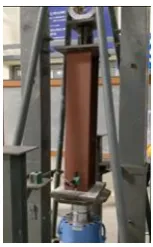
The specimen is being put on the testing frame of 1000 KN capacity. Two LVDT's are put, one is set to the mid-range of the segment to quantify most extreme distortion and another is set on the pivot of the base plate to measure axial shortening of the section. Two strain checks are set, one is fixed at 250mm separation from the base of the segment and another is fixed to the inside mid-range of the area. The strain gauges are associated with the multi-channel data logger. The column is stacked using Self Restraining jack. Uni-axial load is being applied through the jack on to the section and the segment is being checked for its buckling behaviour.
[image:5.595.130.207.622.746.2]13 (b) Test setup of the specimen (GBB200-S25-C20- 4)
[image:6.595.131.206.582.715.2]13 (c) LVDT positioning Table 3
Comparative results of different sections
Specimen Experimental Results
Finite Element
Results
Comparison Deflection at Ultimate
load
Deflection at Ultimate
load
Failure mode
PEXP PFEA PEXP/ PFEA DEXP DFEA -
(KN) (KN) - (mm) (mm) -
BB200-S0-C20- 3 190 156.3 1.21 6.6 2.83 Local
GBB200-S25-C20- 4 250 206.8 1.21 10.68 6.62 Local
FF200-S0-C20- 3 340 315.6 1.07 3.30 2.92 Local
IV EXPERIMENTAL RESULTS
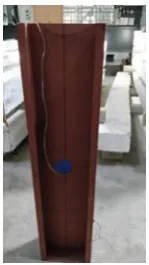
Experimental failure loads and buckling failure modes for the test examples are appeared Table 3. As can be seen, the segment FF200-S0-C20-3 has higher load carrying capacity and structural stability comparing with the rest of the sections. This area achieves the most extreme PEXP load of about 340KN. Fig. 14 demonstrates the buckling failure caused in the specimen when utilization of the Uniaxial load. The failure of the specimen is visualised near the ends of the specimen giving a conclusion that it is local buckling type of failure acting in the column.
(a) Buckling of the specimen (BB200-S0-C20-3)
International Journal of Innovative Technology and Exploring Engineering (IJITEE) ISSN: 2278-3075, Volume-8 Issue-8 June, 2019
(c) Buckling of the specimen (FF200-S0-C20- 3)
IV. RESULTS & DISCUSSION
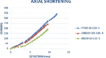
A. Load Vs Deflection (Axial shortening)
Axial shortening of the section is the buckling behaviour of the specimen where the section compresses on application of load. Fig.15 shows the axial compression of the specimens.
B. Load vs Deflection (Buckling)
[image:7.595.334.535.176.283.2]Fig.16 shows the graph plotted for buckling of the specimens by recording the deflection using LVDT’s placed at the mid-span of the specimen.
[image:7.595.79.263.255.356.2]Fig. 15 Load Vs Deflection (axial shortening)
Fig. 16 Load Vs Deflection (Buckling)
C. Load Vs Strain (Axial)
[image:7.595.71.269.421.510.2]Fig. 17 presents the graph plotted for uniaxial load vs strain recorded for the specimen at the axial position. It is used to impact the material performance of the specimens under the provided uniaxial load.
Fig. 17 Load Vs Strain (Axial)
D. Load Vs Strain (buckling)
Fig. 18 presents the graph plotted for uniaxial load vs strain recorded for the specimen at the buckling position. It is used to determine the material quality of the specimens under the provided uniaxial load.
Fig. 18 Load Vs Strain (Axial)
V. CONCLUSIONS
A broad examination has been done on the axial strength of contrary cold formed steel built-up sections are exhibited in this paper. A complete number of 8 distinct sections have been analysed for its compressive behaviour utilizing finite element analysis (ANSYS 18.2). Inspecting the consequences of finite element analysis, 3 sections shows promising load carrying capacity and structural stability contrasted with residual sections. These 3 sections have been decided for carrying out experimental investigation. A total number of 9 tests I.e. 3 distinct sections with 3 trials each have been checked for experimental analysis. By breaking down the experimental investigation results, FF200-S0-C20-3 section furnishes higher load carrying capacity with less deformation contrasted with the remainder of the sections. This section gives about 1.78 times higher load carrying capacity than the basic back-to-back section. The outcomes talked about are on failure modes, load-axial shortening, load-axial strain and deformed shapes amid extreme failure.
REFERENCES
1. Ben Young (2008) “Research on cold-formed steel columns” Thin walled structures 46
2. Benjamin W. Schafer, David C. Fratamico , Kim J.R. Rasmussen, Shahabeddin Torabian , Xi Zhao, , (2018) “Experiments on the global buckling and collapse of built-up cold-formed steel columns” Thin-walled structures 114
3. Dongyu Liu, Hongbo Liu, Xiangwei Liao Zhihua Chen, (2016) “Structural behavior of extreme thick-walled cold-formed square steel columns” Journal of Construction Steel Research 128
4. Hieng Ho Lau, James B.P. Lim, Krishanu Roy, Tina Chui Huon Ting, (2018) “Nonlinear behaviour of back-to-back gapped built-up cold-formed steel channel sections under compression” Thin-walled structures 147
5. Ben Young, Ju Chen (2008) “Column tests of cold-formed steel non-symmetric lipped angle
sections” Journal of
[image:7.595.69.268.665.782.2]AUTHORS PROFILE
Praveen Kumar. S is currently pursuing M.E. in Structural Engineering from SRM Valliammai Engineering College, Kattankulathur, Tamil Nadu, India. Having Bachelor’s degree (2016) from Tagore Engineering College, Chennai, Tamil Nadu, India.