i
SHORT RANGE PHASED ARRAY RADAR SYSTEM FOR LIGHTNING REMOTE SENSING APPLICATION
VENGADESHWARAN KANATHASAN
This Report Is Submitted in Partial Fulfillment of Requirements For The Bachelor Degree of Electronic Engineering (Telecommunications Electronics) With
Honours
Faculty of Electronics and Computer Engineering
Universiti Teknikal Malaysia Melaka
v
DEDICATION
vi
ACKNOWLEDGEMENT
vii
ABSTRACT
viii
ABSTRAK
Projek tahun akhir ini bertujuan untuk membina sistem radar pelabagai peringkat yang boleh beroperasi dalam jangka jarak dekat bagi aplikasi lightning remote sensing. Projek radar pelbagai peringkat ini merupakan satu projek penyelidikan yang mempunyai potensi untuk menyampaikan kajian analisis berdasarkan kilat dalam masa akana datang. Projek ini, mengkompromi reka bentuk, simulasi dan analisis linear antena slot tirus (LTNA). Terdapat unsur-unsur penting yang dianalisis untuk menentukan prestasi antena seperti s-parameter, directivity, corak sinaran, keuntungan dan saham. Kedua-dua keputusan simulasi dan pengukuran telah diperolehi dan dibandingkan, untuk menentukan prestasi antena pada 2.4GHz frekuensi yang ditetapkan. Return loss kurang daripada
-10dB. Dari segi gain, bandwidh dan directivity, masing masing memperoleh sebanyak
ix
TABLE OF CONTENT
CHAPTER SUBJECT PAGE
PROJECT TITLE I DECLARATION ERROR! BOOKMARK NOT DEFINED. SUPERVISOR DECLARATION ERROR! BOOKMARK NOT DEFINED.
DEDICATION V
ACKNOWLEDGEMENT VI
ABSTRACT VII
ABSTRAK VIII
TABLE OF CONTENT IX
LIST OF TABLES XIII
LIST OF FIGURES XIV
LIST OF ABREVIATIONS XVI
x
1.1 Overview of the Project 2
1.2 Objective of the project 3
1.3 Problem statement 3
1.4 Scope of project 4
1.5 Project outcome 4
1.6 Methodology 5
2 LITERATURE REVIEW 6
2.1Introduction 7
2.2Basic antenna parameters 8
2.2.1 Radiation pattern 8
2.2.2 Bandwidth 9
2.2.3 Beamwidth 10
2.2.4 Gain 12
2.3 Directivity 12
2.3.1 Efficiency 13
2.4 Tapered Slot Antenna 13
2.4.1Types of taper profile 14
2.4.2Linear Taper profile 16
2.4.3Aperture width and length 17
2.4.4 Slot line width of LTNA 17
2.4. 5 Microstrip line 18
2.4.6 Antenna port 20
xi
3 PROJECT METHODOLOGY 26
3.1 Design process methodology 29
3.1.1 Substrate Material specifications 30
3.1.2 Micro-strip trace width 30
3.1.3 Antenna length 31
3.1.4 Antenna width 31
3.1.5 Slot-line width of linear tapered slot antenna. 31
3.2 Taper profile of LTSA antenna 32
3.3Simulation of LTNA antenna 32
3.4 Fabrication process of LTNA antenna 34
3.5 Measurement process 36
3.5.1 Return loss measurement 36
3.5.2 Gain measurement 37
3.5.3Radiation pattern measurement 38
4 INTRODUCTION 39
4.1 Initial design 40
4.2 Parametric study 42
4.2.1 Aperture width 43
4.2.2 Antenna length 45
4.2.3 Slot length 48
4.2.4 Slot width 48
4.3 Optimized design parameter 49
4.4 Return loss measurement 52
xii
4.6 Radiation pattern measurement 54
4.7 Antenna testing 56
5 CONCLUSION 57
5.1 Conclusion 58
5.2 Recommendation 60
5.3 Future work 60
REFERENCES 62
xiii
LIST OF TABLES
NO TITLE
RGR
PAGES 2.1 The information on related research papers 21-26
3.1 Substrate specifications 29
4.1 Initial design parameter of LTNA antenna 39
4.2 Fixed design parameter of LTNA antenna 39
4.3 Simulation of initial LTSA design 40
4.4 Varying Parameters for Parametrical Study 41
4.5 Optimized antenna parameters 49
4.6 Optimized antenna results 50
xiv
LIST OF FIGURES
NO. TOPICS PAGES
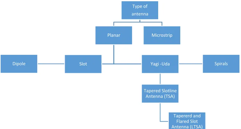
2.1 General category and types of antenna. 8
2.2 Basis geometry of tapered Antenna 10
2.3 Field pattern 11
2.4 Tapered Slot Antenna (TSA) dimensions 14
2.5 Types of taper profile for TSA antenna 15 2.6 Unilateral (left) slotline vs Bi-lateral slotline (right) 16
2.7 Slotline structure 17
2.8 Cross section of microstrip line 19
2.9 Radiation field of microstrip line 19
2.10 SMA connector specifications 20
3.1 LTNA design flow chart 29
xv
3.3 Simulation design process 33
3.4 LTNA antenna fabrication process. 35
3.5 Soldered SMA connector 36
3.6 Calibration of VNA 36
3.7 Return loss measurement setup 37
3.8 Antenna gain measurement setup 37
4.1 Initial design return loss 41
4.2 Analyzed parameters Line 43
4.3 Return loss 44
4.4 Directivity 44
4.5 Half Power Beamwidth (HPBW) 45
4.6 Return loss of varied antenna length 46
4.7 Directivity of varied antenna length 46
4.8 HPBW of varied antenna length. 47
4.9 Return loss of varied slot length 48
4.10 Return loss of slot line parametric study 49
4.111 Return loss for optimized design. 51
4.122 E-field for optimized design. 51
4.13 H-field for optimized design 52
4.14 Return loss (Measured vs Simulated). 52
4.15 Measure radiation pattern for LTNA structure 54-55
4.16 Monitoring setuP 56
4.17 inSSIDer monitoring result 56
5.1 Tapered antenna price 58
5.2 Tapered antenna price 58
xvi
LIST OF ABREVIATIONS
WLAN – Wireless Local Area Network UTeM – Universiti Teknikal Melaka Malaysia
IEEE - The Institute of Electrical and Electronic Engineers FYP – Final Year Project
LTSA – Linear Tapered Slot Antenna TSA - Tapered Slot Antenna
FR – Flame Retardant
1
CHAPTER 1
INTRODUCTION
1 HEADING 3 – CHANGE COLOR TO WHITE BEFORE PRINTING
2
1.1 Overview of the Project
The project is basically a research based project, in which the short term goal has been set to develop a short range phased array radar system. Radar is a detection system that relies on the usage of radio waves to determine the distance, velocity and angle of object. A basic radar system consists several subsystems which compromises of a transmitter antenna, an emitting antenna, a transmitter, a receiver and a processor. According to Gregory L. Chavart [1], the author of Small and Short Range Radar System, phase array radar has been very expensive and conventionally used in air defense system. At MIT Lincoln Laboratory, along with John Peabody and Tyler Ralston, Gregory L.Chavart successfully built a high performance through-wall imaging system using Wi-Fi antennas and pegboard. This has been taken as an inspiration or basis, to create low cost phased array radar that could operate at short range.
In recent years, there has been an increase of popularity to operate radar system at Wi-Fi frequencies. Numerous device operating at 2.4GHz band that complies with Bluetooth, Home RF and IEE 802.11b are widely available in market now. IEEE 802.11b refers to the Wi-Fi adapters that incorporated with commercial pc’s to read Wi-Fi signal. Since, this devices are low in cost, an antenna will be developed to be integrated with the IEE802.11b devices. With that the radio frequency could be interfaced with any computer and therefore enabling the development of radar signal analyzing algorithms by using software such as MATLAB or LabVIEW. One such algorithm is the SAR algorithm. Synthetic Aperture Radar (SAR) is a modern ground mapping technique where high resolution is achieved by a very large aperture that is synthesized over the flight path of an aircraft. This is done by recording reflected radar pulses at known locations along the flight path. The radar must accurately know the aircraft’s position and back-out perturbations in flight path so that all scattered pulses are aligned in time and phase. After that the SAR imaging algorithm is applied to the data to process an image
3
study the scattering particles of clouds and analyzing them. Cloud particles can be divided into three types which are water droplets, supercool water droplets and ice crystal which are located in the intermediate layer of cloud , lower layer of cloud and top of thundercloud respectively. The study an analysis on the cloud particles could lead to the harnessing energy from lightning. Harvesting energy from lightning has been taken up as a solution to depleting unrenewable source by many advanced countries and the race to develop the technology in harvesting the lightning energy among the scientist and engineers is ongoing. However, there are no established and mature studies on this technology and the scientific literature can hardly be found, therefore this project is carried out to be as a sensible part of the research studies [2][3]. Therefore as a stepping stone, the project is initialized with the development of the antenna that could accommodate the radar application. Thus this project will be focusing on the design and development of Linear Tapered Slot Antenna (LTSA) antenna that is capable to operate at 2.4GHz.
1.2 Objective of the project
The objective of the project is to design, simulate, fabricate and measure Linear Tapered Slot Antenna (LTSA) which can function as a radar antenna. The required frequency is 2.4GHz with an operating bandwidth of 200MHz.
4
This problem that will be apprehended in this project is the high cost of the radar system and also the accountability of the radar antenna to function at 2.4GHz. Since, the antenna will be implemented in capturing the scattering particles of cloud, an antenna with an aperture is required. A solution is seek by developing a printed Linear Tapered Slot Antenna that could operate at higher frequencies.
1.4 Scope of project
The scope of the project is to design LTNA antenna that could operate in S-Band region particularly at 2.4GHz. The antenna will be simulated in the CST Microwave studio and fabricated on a negative FR4 board. The simulation results of the antenna in terms of return loss, radiation pattern and gain will be analyzed.
1.5 Project outcome
5
1.6 Methodology
6
CHAPTER 2
LITERATURE REVIEW
2 HEADING 3 – CHANGE COLOR TO WHITE BEFORE PRINTING
7
2.1 Introduction
Antennas are key components of any radar system. A radar antenna is a device that can act as a transmitter or as a receiving device that receives reflected or echo signal and delivers it to the receiver. To be precise, the term antenna is defined as means for radiating or receiving radio waves in free space as per the IEEE Standards of Terms for Antennas [4][5][6]. Basic antenna parameters comprises of return loss, gain, Half-Power Bandwidth (HPBW), First-null Beamwidth (FNBW), directivity, radiation pattern and efficiency. There are many different type of antennas with their respective performance value, however these are the parameters that will characterize the type of antenna and the performance of the antenna based on the application it is being implemented.
8
Figure 2.1: General category and types of antenna.
2.2 Basic antenna parameters
2.2.1 Radiation pattern
Generally, the radiation of antenna is caused by moving electrons. Acceleration and deceleration of charges within the antenna produces different radiation pattern depending on the antenna structure. An antenna radiation can be also defined as a mathematical function or graphical representation of the radiation properties of the antenna as a function of space coordinates [6][7]. The representational of the radiation properties of the radio wave conducting device as a capacity for precise position might make as far as energy pattern and also amplitude field pattern [6].
Type of antenna
Planar
Slot Yagi -Uda