UNIVERSITI TEKNIKAL MALAYSIA MELAKA
MICROCONTROLLER- BASED VOLTAGE AND CURRENT
STABILITY CONTROLLER FOR DOMESTIC APPLICATION
This report is submitted in accordance with the requirement of the Universiti Teknikal Malaysia Melaka (UTeM) for the Bachelor of Electrical Engineering
Technology (Industrial Power) with Honours.
By
NURUL FATIN BINTI ROSDANI B071410114
920813-15-5010
BORANG PENGESAHAN STATUS LAPORAN PROJEK SARJANA MUDA
UNIVERSITI TEKNIKAL MALAYSIA MELAKA
TAJUK: Microcontroller- Based Voltage and Current Stability Controller for Domestic
Application.
SESI PENGAJIAN: 2016/17 Semester 2
Saya NURUL FATIN BINTI ROSDANI
mengaku membenarkan Laporan PSM ini disimpan di Perpustakaan Universiti Teknikal Malaysia Melaka (UTeM) dengan syarat-syarat kegunaan seperti berikut:
1. Laporan PSM adalah hak milik Universiti Teknikal Malaysia Melaka dan penulis.
2. Perpustakaan Universiti Teknikal Malaysia Melaka dibenarkan membuat salinan untuk tujuan pengajian sahaja dengan izin penulis.
3. Perpustakaan dibenarkan membuat salinan laporan PSM ini sebagai bahan pertukaran antara institusi pengajian tinggi.
4. **Sila tandakan ( )
SULIT
TERHAD
TIDAK TERHAD
(Mengandungi maklumat yang berdarjah keselamatan atau kepentingan Malaysia sebagaimana yang termaktub dalam AKTA RAHSIA RASMI 1972)
(Mengandungi maklumat TERHAD yang telah ditentukan oleh organisasi/badan di mana penyelidikan dijalankan)
Disahkan oleh:
** Jika Laporan PSM ini SULIT atau TERHAD, sila lampirkan surat daripada pihak berkuasa/organisasi berkenaan dengan menyatakan sekali sebab dan tempoh laporan PSM ini perlu dikelaskan sebagai SULIT atau TERHAD.
Alamat Tetap:
SBT 0143, Simpang 39,
Kampung Sungai Bangat
87000, W.P Labuan.
Tarikh: ________________________
Cop Rasmi:
DECLARATION
I hereby, declared this report entitled “Microcontroller- Based Voltage and Current Stability Controller for Domestic Application” is the results of my own
research except as cited in references.
Signature : ………..
Author’s Name : NURUL FATIN BINTI ROSDANI
APPROVAL
This report is submitted to the Faculty of Engineering Technology of UTeM as a partial fulfilment of the requirements for the degree of Bachelor of Electrical Engineering Technology (Industrial Power) with Honours. The member of the supervisory is as follow:
……….
i
ABSTRAK
ii
ABSTRACT
iii
DEDICATION
To my beloved parents
Rosdani bin Mohamad
Kartini binti Awi
Farizal bin Zainal
Rosenita binti Mohd Hussin
Siblings
Norsyafiqah binti Rosdani
Saiddatul Syazwina binti Farizal
Syazriel Sufian bin Farizal
Luqman Hakim bin Rosdani
Athirah binti Rosdani
Supervisor
Associate Professor Mohd Ariff bin Mat Hanafiah
iv
ACKNOWLEDGEMENT
v
TABLE OF CONTENT
Abstrak i
Abstract ii
Dedication iii
Acknowledgement iv
Table of Content v
List of Table viii
List of Figure ix
List Abbreviations, Symbols and Nomenclatures xi CHAPTER 1: INTRODUCTION
1.0 Background of Project 1
1.1 Problem Statement 1
1.2 Objectives of Project 2
1.3 Scope of Project 2
1.4 Organization of Report 3
1.5 Summary 3
CHAPTER 2: LITERATURE REVIEW
2.0 Introduction 4
2.1 Theory and Literature Review: The Voltage and Current Stability Controller for Domestic Application.
2.1.1 Definition of Over Current and Over Voltage 4 2.1.2 Causes of Under and Over Voltage
2.1.2.1Cause of Under Voltage 6
2.1.2.2Cause of Over Voltage 8
2.1.3 Important of Protection System 11
2.1.4 Type of Protection System
2.1.4.1 Non-Unit Protection 12
2.1.4.2 Unit Protection 13
2.2 Summary 14
CHAPTER 3: METHODOLOGY
vi
3.1 Research Flow 16
3.2 Software Development 16
3.2.1 Schematic Circuit 17
3.2.2 Coding 18
3.2.3 Burning Coding to the Microcontroller 20
3.3 Hardware Development 22
3.3.1 Operation of the Circuit 22
3.3.2 Device and Component Used in the Circuit 23
3.3.2.1Microcontroller 23
3.3.2.2Isolator Switch 25
3.3.2.3Step Down Transformer 26
3.3.2.4Liquid Crystal Display(LCD) 27
3.3.2.5 Capacitor 28
3.3.2.6Resistor 28
3.3.2.7 Diode 29
3.3.2.8 Transistor 30
3.3.2.9Relay 31
3.4 Summary 32
CHAPTER 4: RESULT AND DISCUSSION
4.0 Introduction 33
4.1 Simulation Result 33
4.2 Hardware Result 39
4.3 Summary 41
CHAPTER 5: CONCLUSION
5.0 Introduction 42
5.1 Summary of Research 42
5.2 Achievement of Research Objectives 42
5.3 Recommendation 43
APPENDIX A 44
APPENDIX B 51
vii
APPENDIX D 81
APPENDIX E 84
APPENDIX F 88
APPENDIX G 91
viii
LIST OF TABLES
2.1.3(a) Power System Protection Area 11
2.1.3(b) Effect of Live Current on Human 12
ix
LIST OF FIGURE
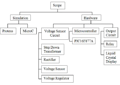
1.3 Division of Work Scope Project 2
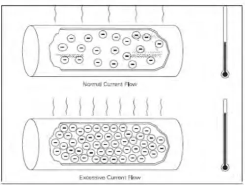
2.1.1 Over Current Flow 4
2.1.2.1(a) Under Voltage Waveform 6
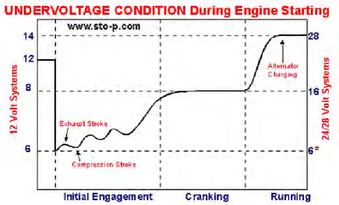
2.1.2.1(b) Graph of Under Voltage Condition during Engine Starting 7
2.1.2.2(a) Over Voltage Waveform 9
2.1.4.1 One Line Diagram Typical Non-Unit Protection 13 2.1.4.2 Differential Fault Current Measurement 14
3.1 Research Flow Activities 16
3.2.1 Schematic Circuit Constructed Using Proteus Software 17 3.2.2 Flow Chart of under and Over Voltage Protection System 19
3.2.3(a) SK40C 21
3.2.3(b) UIC00B 21
3.3 Block Diagram of Smart Under and Over Voltage
Protection System 22
3.3.2.1(a) Microcontroller 16F877A 23
3.3.2.1(b) Pin Diagram of PIC16f877A 24
3.3.2.1(c) Crystal 20MHz 24
3.3.2.1(d) Configuration of Crystal Oscillator 25
3.3.2.2 Isolator Switch 25
3.3.2.3 Step Down Transformer 26
3.3.2.4(a) Liquid Crystal Display 27
3.3.2.5 22pF Ceramic Capacitor 28
3.3.2.6(a) Fixed Resistor 28
3.3.2.6(b) Potentiometer 29
3.3.2.7 Diode 29
3.3.2.8 2N3904 of NPN Type of Transistor 30
3.3.2.9 Relay 31
xi
LIST ABBREVIATIONS, SYMBOLS AND
NOMENCLATURES
MCB - Miniature Circuit Breaker ASD - Adjustable Speed Drive
PLC - Programmable Logic Controller R.M.S - Root Mean Square
L - Inductance kHz - Kilohertz HZ - Hertz I - Current R - Resistor V - Voltage
A - Ampere
Ω - Ohm
mA - Mili Ampere
AC - Alternating Current IDMT - Definitely Minimum Time CT - Current Transformer F - Fault
DC - Direct Current kΩ - Kilo Ohm D - Diode
LCD - Liquid Crystal Display ADC - Analogue to digital converter CPU - Central Processing Unit NO - Normally Open
1
CHAPTER 1
INTRODUCTION
1.0 Background of Project
The main intention of this project is to design a microcontroller based voltage and current stability controller for domestic application. This project is to develop a device that can be installed in the domestic distribution board in order to detect the instability of the current and voltage, hence securing the outage caused by the tripping of the main MCB. This project intended to design a microcontroller based system that will intelligently monitor the stability and the safety, hence protect the equipment in the main MCB and facilitates in case any problem occur which contributed to the instability of the current and voltage.
1.1 Problem Statement
2
1.2 Objective Project
The specific objectives for this project are to:
1. To design a controller for domestic application by using microcontroller PIC16F877A.
2. To develop a device that can be installed the domestic distribution board. 3. To analyse the instability of the current and voltage.
1.3 Scope of Project
[image:17.595.117.518.415.700.2]The investigation carried out in this project is limited to protection that will focuses in domestic distribution board at home. The project is divided into two parts, the first one is simulation using software and the second is hardware development. The division of scope:
3
1.4 Organization of Report
This report consists of five chapters begin with report introduction and end with conclusion. The remainder chapters are literature review, methodology and results as well as discussion. Literature review covers overview and method to provide protection in instability of the current and voltage. Meanwhile, methodology shows sequence of works in order to develop this project. Results of implementation of this project will be written in chapter four along with its discussion. Chapter five will delivers conclusion and recommendation for future planning. However, results with discussion and conclusion will be continued in Bachelor Degree Project II.
1.5 Summary
4
CHAPTER 2
LITERATURE REVIEW
2.0 Introduction
This chapter will discuss the significant part of the voltage and current stability controller for domestic application; how this abnormality happened continue with voltage and current protection. Information gains from this research will be used all over project assessment.
2.1 Theory and Literature Review: The Voltage and Current Stability Controller for Domestic Application.
[image:19.595.211.461.495.684.2]2.1.1 Definition of Over Current and Over Voltage
5 According to National Electrical Code on over current protection for equipment and conductors by Mike Holt (2012) determines the over current as any current more than rated current of equipment or ampacity a conductor. It may result from overload, short circuit, or ground fault. Electric current flow in a conductor always generates heat. That larger electric current flows, that warmer the conductor. Damaging excess heats to electronic component. For that purpose, conductor have a consider carrying capacity during continuous or ampacity. Over current protection equipment applied to protect conductor from excess electric current flow.
The over current or excess current is a larger than intended electric current flows through a conductor, lead to heat excess generation, and fire risk or damage to equipment. A few possible causes to over current is short circuit, ground fault, mechanical failure of components, reduction in flux, failure one of supply phase, insulation excess burden failure, and incorrect design.
6
2.1.2 Causes of Under and Over Voltage
2.1.2.1 Cause of Under Voltage
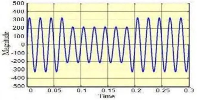
[image:21.595.186.517.323.492.2]Under voltage defined as a fall suddenly in root mean square (r.m.s) voltage and is usually characterized by remained (detained) voltage. Under voltage is short period reduction in r.m.s voltage, mainly attributable short circuit, starting of large motor beginning and equipment failure. Furthermore, under voltage may be classified by their period as shown in
Figure 2.1.2.1(a): Under Voltage Waveform
7 Under voltage irregularity also may result from nature and system failure whether by damaging equipment or operating condition. One of the factors which caused under voltage is unsuitable cable usage or equipment. Based on Ponnle (2015) usage under assessed cable is from substation into industry or house cause large voltage drop in every termination to building. Hence, it provide loss or power or voltage finally consumer distribution unit. Apart from that, most of substation installed under assessed transformer due to low energy request in a few previous year. When high demand, this under voltage problems occur because of incomprehensive planning on energy consumption in the future leads.
[image:22.595.188.537.464.675.2]The Kapoor et al. (2014) states that another factor that leading to under voltage problem heavily payload operations from distribution voltage that is low. The Paul et al. (2015) states that when induction motor in three load balanced phase, start them increase will attract beginning that is less identical high much current in all phases that leading to under voltage problem.
8 The equipment failure also became one of the factors which made presence of under voltage. Failure equipment can cause whether from breakdown the insulation, heating or short circuit. Furthermore, fault happened will make circuit breaker open suddenly and then decided feeding line temporarily. It will form under voltage in other feeder line from same substation (Paul et al. 2015).
Extraordinary nature powers and atmospheric condition (Ponnle 2015) is also one of the factors which caused under voltage problems. Based on Paul et al. (2015), a total that is important under voltage happen when power line face lightning strike. Pollution that came from salt in power line in coast produce lightning on when storm enter since salt is a good conductor.
2.1.2.2 Cause of Over Voltage
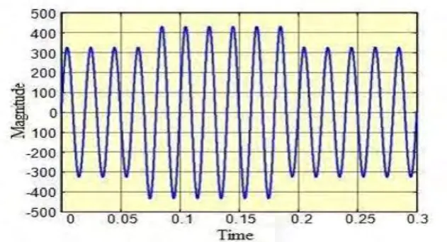
9 Figure 2.1.2.2(a): Over Voltage Waveform
This is cause of over voltage are mostly due to energization capacitor bank. It also could be generated by sudden load deduction. Due to load determining have decline suddenly current, which will cause voltage of which L is line induction. The effect of over voltage is more severe and destructive. It can cause the electrical appliances fail, expected overheated due to high voltage. Also electronic and tool that is other sensitive is inclined towards malfunction.
Over voltage in power system is due to purposes that various. Over voltage emerges at a power system can be usually classified to two main categories (Ram & Vishwakarma 2011) which are external over voltage and internal over voltage.
i) External Over Voltage
The atmospheric disturbance especially light is this main cause over voltage. This over voltage is take form a unidirectional impulse that highest amplitude possibility has no direct relationship with operating of systems voltage (Ram & Vishwakarma, 2011, pg592).