Technical Note
Repeatable pre-cracking preparation for fracture testing
of polymeric materials
Nithiananthan Kuppusamy, Rachel A. Tomlinson
⇑Department of Mechanical Engineering, The University of Sheffield, Mappin Street, Sheffield S1 3JD, UK
a r t i c l e i n f o
Article history:
Received 7 December 2015 Accepted 9 December 2015 Available online 17 December 2015
Keywords: Fracture parameter
Linear elastic fracture mechanics (LEFM) Natural crack
Notch Pre-crack
a b s t r a c t
Currently, in order to create a sharp pre-crack in a polymeric material for fracture tough-ness testing, a hand-held razor blade is used. This technique produces cracks of varying angle, length, and crack-front shape. Additionally, there are considerable safety concerns regarding the handling of sharp razor blades. A repeatable, safe method of producing a consistent, sharp pre-crack of a specified length, orientation and crack front is presented here, by use of a simple custom fixture. The specimen preparation procedure has wide applicability for fracture analysis of many brittle materials.
Ó2015 The Authors. Published by Elsevier Ltd. This is an open access article under the CC BY license (http://creativecommons.org/licenses/by/4.0/).
1. Introduction
Composite materials are substituting more conventional materials in load-bearing applications in many industries in order to reduce the weight of a component and provide bespoke material properties. As a result, composite materials are being used in applications in which structural integrity of the component is critical. Therefore, the accurate determination of fracture toughness parameters is becoming increasingly important in the characterisation of the mechanical properties of a composite material in the development process. Several standards exist to assist in this testing process, for example, ASTM E399[1], for the determination of plane strain fracture toughness of metals which was first issued in 1970. A similar proce-dure for testing plastic materials, ASTM D5045[2]was issued in 1990; followed by aStandard Test Method for Determining JR Curves of Plastic Materials(ASTM 6068), issued in 1996. BS ISO 13586:2000,Plastic – Determination of Fracture Toughness (GICand KIC) – Linear Elastic Fracture Mechanics (LEFM) Approachwas issued in 2000.
This long history of standards could lead a person to naively assume that performing a plane strain fracture toughness test for a polymeric material would be straightforward. A fracture toughness test requires a number of notched specimens all containing a pre-crack, of known length, which is introduced to simulate a natural crack into the material. Both the British International Standard (BS ISO) 13586:2000[3]and American Standard Test Method (ASTM) D5045[2], which guide testing for the plane strain fracture toughness of polymers, indicate that the pre-crack should be created naturally by tapping at the centre of the notch with a new razor blade. The standards alternatively suggest creating a pre-crack by sliding a new razor blade in either a sawing motion (side-to-side) or slicing repeatedly in a single direction. If it is not possible to create a pre-crack using the above methods, the standards warn not to apply pressure to the new razor blade on to the centre of the notch, since this could introduce residual stresses at the tip of the natural crack and effectively alter the measuredKIcvalues [2,3]. It is suggested in the ASTM D6068[4], that pre-cracking may be performed by induced fatigue cycles, however this is
http://dx.doi.org/10.1016/j.engfracmech.2015.12.007
0013-7944/Ó2015 The Authors. Published by Elsevier Ltd.
This is an open access article under the CC BY license (http://creativecommons.org/licenses/by/4.0/). ⇑Corresponding author.
E-mail addresses:[email protected](N. Kuppusamy),[email protected](R.A. Tomlinson). Contents lists available atScienceDirect
Engineering Fracture Mechanics
time consuming and it is quite difficult to achieve a fatigue crack in a brittle material without unwanted fast fracture. Additionally, for testing of plastics (E1820), the shape of the notch is strictly defined, whereas in fracture testing of metals (ASTM E399[1]and ASTM E1820[5]), the production of the notch is less restrictive.
If the notch and the pre-crack are not introduced correctly and consistently then this has a detrimental effect on the frac-ture parameters determined, therefore accurate, repeatable specimen preparation is vital. Fracfrac-ture specimen preparation is more challenging in brittle, polymer materials, since very little energy is required to propagate a crack in such materials, thus more controlled procedures are needed.
The aim of this paper is to evaluate critically the methodologies for introduction of pre-cracks recommended in the frac-ture testing standards for polymeric materials, particularly focusing on ease of use and repeatability. A more efficient, repeat-able method to generate a pre-crack of specified length is then developed.
2. Development of methodology
It is observed in BS ISO 13586:2000[3]that it is vitally important to use specimens containing a sharp, pre-crack in order for the Linear Elastic Fracture Mechanics (LEFM) theories to be valid. Good experimental practise dictates that several tests should be performed. The standard states that these specimens should have similar crack lengths to within 0.5 mm of each other. The current hand-held technique used to introduce a pre-crack into a test specimen utilises a razor blade and some skill is needed in avoiding manufacturing a pre-crack length in brittle materials that is too long, or fracturing the specimen completely.
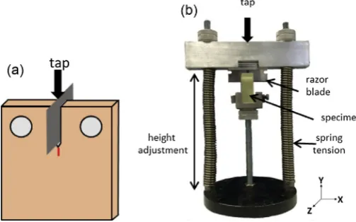
Although it is possible to possess the necessary skill to propagate a pre-crack, it is still very difficult to achieve a repeat-able natural crack length using a razor blade.Fig. 1(a) shows how the blade is positioned by the operator into the machined notch and tapped vertically to propagate a crack. The tapping force needed is very subjective depending on the material and the operator. This procedure requires good coordination and bi-lateral stable positioning to achieve a natural crack. Holding a razor blade at the correct angle and tapping the hammer simultaneously is challenging and has associated risks. Therefore, a prototype rig was designed to introduce some control into the procedure.
2.1. Prototype pre-crack rig
The prototype pre-crack rig was designed to aid in creating a natural crack onto the test specimen presented inFig. 1(b). The rig clamps the specimen and holds the razor blade within the notch fixed in thex–yplane. The razor blade is positioned just touching the tip of the notch, then the top of the fixture is tapped with a hammer by the operator. The guide springs ensure that there is no rotation of the razor blade about thezaxis oryaxis and also ensures that no compressive force is applied to the notch surface apart from the operator’s tapping force.
Nomenclature
c critical value G energy release rate
[image:2.544.146.398.517.674.2]K stress intensity factor, MPapm
Although the pre-crack rig was able to tackle the operator’s coordination problems, and hence out-of-plane cracks are prevented, it was not possible to achieve complete control of the length of the pre-crack produced using this rig. The applied tapping force still depends on the operator’s consistency and the material properties. Additionally, producing a repeatable pre-crack is more challenging in polymers containing toughening particles or short fibres due to the unpredictability of such material. Finally, the risks of using a razor blade have been reduced, but not completely eliminated. Therefore, an alternative method was investigated.
2.2. Further development
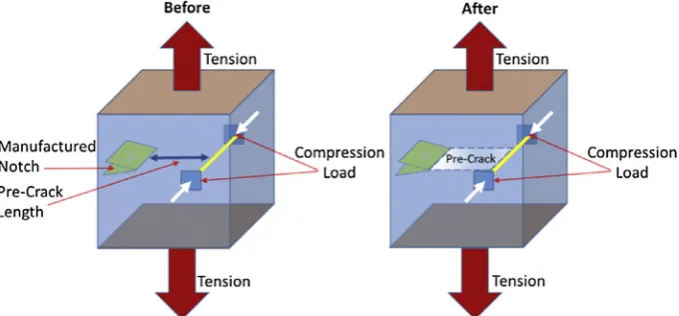
A technique for ‘‘growing” a pre-crack in a brittle material was proposed by Tamura et al.[6]. This general method is illus-trated inFig. 2, where a pre-crack is generated by applying loading in two directions. An initial compression load is applied in the transverse direction, normal to the surface of the specimen, ahead of the manufactured notch and a secondary tension load is applied with a tensile test frame via loading pins in the direction to open the crack. Tensile loading commences the growth of the pre-crack until the required length is achieved, the compressive load causing crack arrest. Tamura et al. described results in a variety of brittle materials but did not supply enough experimental detail to allow easy replication of the method. They also noted that crack fronts of variable shapes were observed and appeared not to be controllable.
This basic theory has been developed into a simple practical method to grow cracks of a repeatable, defined length; with-out the use of a razor blade, thus increasing the safety of the preparation method.
2.2.1. Application of the loads
The application of the compressive load was investigated using modified Arcan-type specimens[7,8]made from an untoughened epoxy resin used in aerospace composites. Two clamps, a G clamp and simple tool-makers clamp (T-clamp) were used to apply the compressive load and these generated very different crack front shapes. The G-clamp produced a curved crack front, whereas the T clamps generated a very straight crack front.
Fig. 3illustrates the key differences between the G-clamp and T-clamp compressive force contact areas. The G-clamp applies a Hertzian-type contact of a ball on a plane, resulting in a small circular contact point; whereas the T-clamp is a lar-ger, flat, rectangular contact area. Hence as the crack meets the area under load, they-direction dimension of the T-clamp is much larger than that of the G-clamp. In some cases, the contact area of the G-clamp was not sufficiently big to arrest the crack which propagated around the contact area. Additionally, the T-clamp generated a uniform stress through the thickness of the material, hence generating a straight crack front when compared with the crack front from the G-clamp. Therefore, the T-clamp was chosen to apply the compressive loads.
3. New methodology
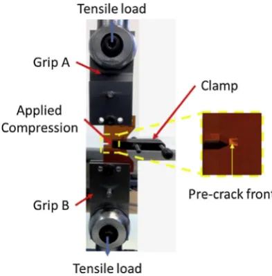
The new methodology requires a tool-makers clamp to apply a compressive load ahead of the notch, and a tensile load is applied to achieve the desired pre-crack length. The apparatus is shown inFig. 4.
3.1. Determination of optimum compressive load
[image:3.544.101.441.513.671.2]An experiment was conducted to determine the compressive load required for production of a pre-crack of known length. The compressive load was applied using a 0–5 N m slipper torque wrench on the T-clamp. The compressive load applied to
the specimen per unit torque on the clamp was determined by compressing a calibrated load cell with the clamp; 0.5 N m of torque resulted in 100 N of force.
A compressive load of 100 N was applied to an untoughened epoxy modified Arcan specimen using the apparatus inFig. 4. The tensile load was increased slowly until the crack started to propagate and then the load was removed immediately since the crack grew rapidly. The arrest point of the crack was observed. The compressive load was increased in 100 N steps and the experiment repeated on a new specimen at each step.
The desired point of arrest of the crack was the front edge of the clamp.Fig. 5illustrates the behaviour of the pre-crack in the modified Arcan specimens with variation of transverse compressive load. If the load was insufficient then the pre-crack either propagated fully through the specimen or arrested further than the desired point. If the load was adequate then pre-crack arrested at the desired point. If the compressive load was too large, then the tensile load needed to initiate the pre-crack was also large and the result was that the pre-crack travelled along the axis and then bifurcated and propagated perpendic-ular to the pre-crack axis as shown inFig. 5(c).
The optimum compressive load for this material using a 4 mm thick specimen was 300 N and approximately 300 N ten-sile load was also required to initiate the crack.
Following the removal of the compressive load, each specimen was observed in a dark field circular polariscope[9]to evaluate the effect of compressive loading. The polariscope allows a visualisation of the residual strains.
[image:4.544.173.362.54.147.2]By observingFig. 6, a qualitative comparison of the residual strains can be made in specimens where cracks have been propagated using the T-clamp method (Fig. 6(a)) and the razor tapping method (Fig. 6(b)). The specimens inFig. 6(a and b) were manufactured using a CNC machine; the specimen inFig. 6(c) was manufactured using traditional machining tech-niques. The traditional machining methods clearly introduce large residual strains, whereas the specimen inFig. 6(a) shows that the CNC machining eliminates all machining strains. The razor tapping method introduces a small amount of residual strain at the notch, and also at the crack tip; however the compressive load in the T-clamp method does not cause any resid-ual strain to remain in the specimen. This is important because if residresid-ual stresses remained this will have a detrimental effect on the accuracy of the subsequent fracture toughness test.
Fig. 3.Contact areas of the compressive load of (a) the G-clamp and (b) the T-clamp.
[image:4.544.174.371.191.391.2]3.2. Repeatability of the method
The pre-crack experiment was repeated on 40 identical untoughened epoxy modified Arcan specimens, with the front edge of the T-clamp positioned at exactly 2 mm from the notch. The T-clamp applied 300 N of compressive force and 300 N tensile force was applied to initiate the crack. The length of both sides (A and B) of the subsequent pre-crack which propagated was measured using a calibrated microscope and the results are shown inFig. 7.
35 of the 40 pre-cracks were exactly 2 mm in length to an accuracy of 10
l
m. The high repeatability is attributed to the ability of the flat faces of the clamp to apply an appropriately distributed compressive force to arrest the crack at a given distance.4. Discussion
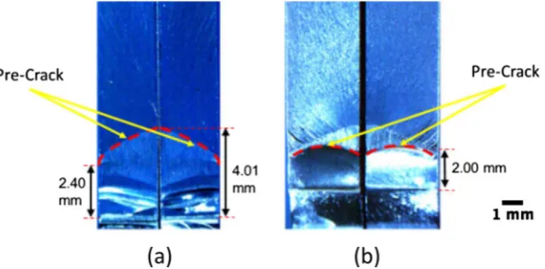
The specimens prepared by the several different pre-cracking methods were used in fracture toughness tests and the images of the fractured pairs of crack faces are shown inFig. 8.
[image:5.544.99.440.55.182.2]When using a razor blade, it is quite common to obtain a crack where the length varies through the thickness.Fig. 7(a) illustrates this and shows a 1.51 mm difference in crack length through the thickness.
[image:5.544.98.443.219.318.2]Fig. 5.An illustration of pre-crack ‘‘grown” with varying transverse compressive loads on an untoughened epoxy resin.
Fig. 6.Showing residual strain CNC-machined specimens with a crack introduced (a) using the T-clamp method; (b) using razor tapping; and (c) a specimen
machined using traditional machining methods (notch only). The specimens were viewed in a white-light, dark field, circular polariscope[9].
1 1
35
1 2
1 2
33
2 2
1.98 1.99 2 2.01 2.02
A B
(mm) A B(mm) A (mm)B A (mm)B A (mm)B (mm)
[image:5.544.143.395.553.674.2]The T-clamp method has proved to reduce this through-thickness variation; as shown inFig. 8the crack lengths are the same on both sides of the specimen, with only a small curvature of the crack front. This slight curvature is common in metal-lic pre-cracking and is due to the constraint of the material.
If the crack length changes through the thickness, then the calculation of the fracture toughness will use an average of measured crack lengths.
The current methodology has been developed for use in Digital Image Correlation experiments[10,11]. The image of one side of the specimen is recorded at increments of load during the fracture test and strain maps determined from these images. The Williams series is then fitted to these strain maps in order to determine the stress intensity factor and fracture toughness. If the crack length is different on the front and rear faces of the specimen, then the stress intensity factor will vary. Tests are also being carried out on many different formulations of particle-toughened epoxy resins and it is good exper-imental practise to have identical specimen dimensions and only change the material in order to understand the material behaviour. Hence it is important to have a uniform pre-crack.
Although this method has been proved highly repeatable and controllable, the tests conducted here were for a single material of a single thickness. If the material thickness or formulation were changed, then the compressive load and tensile load required would vary. Hence it is recommended to use the procedure outlined in Section3.1to determine the optimum compressive load to arrest the crack and then use this load for subsequent pre-cracking. This approach was similarly conducted by Tamura et al.[6]to identify adequate loading condition for pre-cracking.
In addition to the repeatability and control afforded by the new method, razor blades are no longer needed thus reducing risks to the operator. The new method also reduces material and time wasted due to accidentally fracturing specimens during the pre-cracking process which is common with the un-controlled razor blade method.
5. Conclusion
A simple procedure for generating pre-cracks in brittle polymeric materials has been developed from the technique proposed by Tamura et al.[6]. The new methodology achieves highly repeatable, controllable pre-crack lengths and shapes in specimens for the investigation of fracture parameters, with significantly reduced waste of time and materials.
Acknowledgements
The authors would like to thank Cytec Engineered Materials and the Engineering and Physical Sciences Research Council for their financial support and also Mr Richard Kay for his assistance and support in specimen preparation.
References
[1] ASTM. Standard test method for linear-elastic plane-strain fracture toughnessKIcof metallic materials. In: ASTM stand. E 399-12e3. p. 33 [2] ASTM. Standard test methods for plane-strain fracture toughness and strain energy release rate of plastic materials. In: ASTM stand. D5045, no. 14;
2014. p. 10.
[3]Standard B. Plastic – determination of fracture toughness (GIC and KIC) – linear elastic fracture mechanics (LEFM) approach. British Standard International Standard Organisation, International Standard Organisation; 2000.
[4] ASTM. Standard test method for determining J–R curves of plastic materials. In: ASTM stand. D 6068-10, no. 10. p. 8. [5] ASTM. Standard test method for measurement of fracture toughness. ASTM stand. E 1820-13; 2013. p. 54.
[6] Tamura Tamura K, Hasjimoto S. A precrack introducing method in CT-specimens for measuringKICvalues of brittle materials. In: 15th International conference of experimental mechanics. ICEM15. Portugal; 2011. p. 7.
[image:6.544.121.429.54.206.2][7]Banks-Sills L, Arcan M, Bortman Y. A mixed mode fracture specimen for mode II dominant deformation. Engng Fract Mech 1984;20(1):145–57. [8] Jones S. An experimental investigation of the fracture behavior of particulate toughened epoxies. Thesis; 2013. p. 224.
[9] Tomlinson RA, Kuppusamy N. Repeatable fracture specimen preparation for 2D and 3D digital image correlation. In: 16th International Conference of experimental mechanics. Cambridge (UK): ICEM; 2014. p. 2.
[10] Michael J-JO, Sutton Hubert A, Schreier W. Image correlation for shape, motion and deformation measurements – basic concepts. In: Theory and applications. Springer; 2009.