Networks
.
White Rose Research Online URL for this paper:
http://eprints.whiterose.ac.uk/110443/
Version: Accepted Version
Article:
Hassen, F and Mhamdi, L (2017) A Scalable Multi-Stage Packet-Switch for Data Center
Networks. Journal of Communications and Networks, 19 (1). pp. 65-79. ISSN 1976-5541
(c) 2017 IEEE. Personal use of this material is permitted. Permission from IEEE must be
obtained for all other users, including reprinting/ republishing this material for advertising or
promotional purposes, creating new collective works for resale or redistribution to servers
or lists, or reuse of any copyrighted components of this work in other works.
[email protected] https://eprints.whiterose.ac.uk/
Reuse
Unless indicated otherwise, fulltext items are protected by copyright with all rights reserved. The copyright exception in section 29 of the Copyright, Designs and Patents Act 1988 allows the making of a single copy solely for the purpose of non-commercial research or private study within the limits of fair dealing. The publisher or other rights-holder may allow further reproduction and re-use of this version - refer to the White Rose Research Online record for this item. Where records identify the publisher as the copyright holder, users can verify any specific terms of use on the publisher’s website.
Takedown
If you consider content in White Rose Research Online to be in breach of UK law, please notify us by
A Scalable Multi-Stage Packet-Switch for Data
Center Networks
Fadoua Hassen,
Student Member, IEEE,
and Lotfi Mhamdi,
Member, IEEE
Abstract—The growing trends of data centers over last decades including social networking, cloud-based applications and stor-age technologies enabled many advances to take place in the networking area. Recent changes imply continuous demand for bandwidth to manage the large amount of packetized traffic. Cluster switches and routers make the switching fabric in a Data Center Network (DCN) environment and provide interconnectiv-ity between elements of the same DC and inter DCs. To handle the constantly variable loads, switches need deliver outstanding throughput along with resiliency and scalability for DCN require-ments. Conventional DCN switches adopt crossbars or/and blocks of memories mounted in a multistage fashion (commonly 2-Tiers or 3-Tiers). However, current multistage switches, with their space-memory variants, are either too complex to implement, have poor performance, or not cost effective. We propose a novel and highly scalable multistage switch based on Networks-on-Chip (NoC) fabrics for DCNs. In particular, we describe a three-stage Clos packet-switch with a Round Robin packets dispatching scheme where each central stage module is based on a Unidirectional NoC (UDN), instead of the conventional single-hop crossbar. The design, referred to as Clos-UDN, overcomes shortcomings of traditional multistage architectures as it (i) Obviates the need for a complex and costly input modules, by means of few, yet simple, input FIFO queues. (ii) Avoids the need for a complex and synchronized scheduling process over a high number of input-output modules and/or port pairs. (iii) Provides speedup, load balancing and path-diversity thanks to a dynamic dispatching scheme as well as the NoC based fabric nature. Simulations show that the Clos-UDN outperforms some common multistage switches under a range of input traffics, making it highly appealing for ultra-high capacity DC networks.
Index Terms—Next-Generation Networking, DCN, Clos-network, NoC, packet dispatching, packet scheduling
I. INTRODUCTION
I
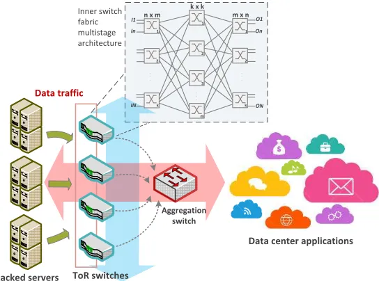
N addition to virtualization, the on-going transformationof large-scale networks like DCNs is mainly realized through increasing the available bandwidth by means of high-performance and scalable switches/routers to ensure smooth and consistent enhancement for future needs. Targeting agility, Top of Rack (ToR) switching architecture can be adopted in a DCN for ease of network scaling and better power and cabling management (Fig.1). ToR switches need to be high-performance elements of high number of I/O ports to connect in rack servers. In this context, aggregate throughput, latency, complexity and power consumption are key considerations when designing switches for DCN environment [1]. Com-monly, hierarchical switching fabrics are built to manage the floating traffic in DCNs. Single-stage crossbar switches do not meet the growing networking requirements. While they
The authors are with the School of Electronic and Electrical Engineering, Institute of Integrated Information Systems,University of Leeds, UK (e-mail:[email protected]; [email protected]).
can be implemented for small-sized switches, they become quite complex to implement and unscalable for growing port counts (beyond 64 ports) [2] [3]. Other design approaches have been investigated, such as multistage switches where many smaller crossbar fabrics are arranged in cascade. They have been typical commercial solutions for high-speed routers [4] mainly because they can be incrementally expanded by adding more modules to the existing design. Besides, they have numerous benefits such as being partially or completely non-blocking, providing good broadcast and multicast features and build in reliability with no or minimum failure in the system. Dell S-Series 100M/1G/10G/40GbE ToR switches have been designed and optimized to leverage a non-blocking architec-ture that delivers low-latency switching and increase scalability at the DC network edge [5]. Cisco designed the Nexus 5000 Series ToR switches to support flexible deployment and to meet the scalability demands of today’s data centers [1]. Juniper also provides the EX4550 line switches that fit for high density data center ToR deployments [6].
One of the most popular multistage arrangements is the three-stage Clos-network that is frequently used for telecom-munications and networking systems [7] [8]. The buffer place-ment defines the type of the multistage Clos switch which
can be a Space-Space-Space (S3
Racked servers ToR switches
Data traffic
Data center applications
.
.
.
..
.
.
.
.
O1
ON On
.
.
.
..
.
..
.
I1
In
. . .
. . . n x m
k x k m x n
IN
. . .
1
2
k 1
2
k 1
2
m 3 Inner switch
fabric multistage architecture
[image:3.612.184.456.74.276.2]Aggregation switch
Fig. 1: Abstraction of a ToR switching architecture in a Data Center Network
fabrics design as it addresses a number of limitations of conventional single-hop crossbars, including scalability, port speed and path diversity [15]. A number of recent designs have used the NoC concept in high-performance switching. A design for Ethernet switches has been described in [16] [17]. A Unidirectional NoC crossbar fabric based packet switch (UDN) design has been described in [15] [18] along with appropriate NoC routing algorithms. An extension of this design, termed MultiDirectional NoC (MDN) packet switch has been also proposed in [19]. More recent results [20] proposed an implementation of a single-stage crossbar fabric using NoC-enhanced FPGA and different routing algorithms. Despite the high potential of NoC based crossbar fabrics, their application has been restricted to single-stage crossbar packet switches.
In our previous work, we proposed the first design of a scalable multistage packet-switches based on NoC fabrics for DCNs [21]. In particular, the switching fabric is a combination of a Clos macro-design, that reports to the whole fabric architecture, and a UDN micro-design for the central switching modules of the packet-switch. We describe a three-stage Clos-network with FIFO input queues and a dynamic dispatching of packets to the central modules. The proposed switching architecture has several advantages over earlier multistage packet-switches. In particular:
• The Clos-UDN obviates the need for a complex and
costly input queuing structure. Unlike conventional mul-tistage design where a high number of fast Virtual Output Queues (VOQs) is required, the Clos-UDN uses a small number of input FIFO queues which need not to run faster than the external line rate.
• The proposed Clos-UDN avoids the need for complex,
costly and slow centralized scheduling process. Conven-tional multistage Clos-networks require complex
schedul-ing process with global synchronization between inputs and outputs. Our proposal relies on the UDN stages to route input packets to their outgoing interfaces by means of fully distributed, parallel and independent NoC routers’ decisions.
• The Clos-UDN inherits all the advantages of the UDN
design in terms of scalability, speedup and path diversity [15]. These properties result in high performance in terms of low latency, high-throughput and efficient hardware design.
Out-of-sequence packets delivery is a common problem to all multistage packet switch architectures with buffered middle stages. A re-sequencing mechanism at the output stage of the switch [10] is a popular solution to this phenomenon. In [10], are discussed two re-ordering mechanisms based on time-stamp monitoring that is performed either at the input modules IM switch) or at the output modules (MMM-OM switch). Although both alternatives do not require any synchronization among the different blocks, many buffers and arbiters have been introduced making the solutions
un-scalable. In [8], H. J. Chao et al. proposed a multi-plane,
multistage buffered switch with several re-sequencing mech-anisms including: Static and dynamic hashing, time stamping and window-based re-sequencing. It is worth mentioning that almost all previously suggested approaches rely on complex algorithms [22] and imply the use of numerous schedulers and buffers [10] [23]. We suggest a simple way to alleviate the packets mis-sequencing in the Clos-UDN switch. We show that a static configuration of the input and the central stage modules connections used along with the appropriate routing algorithm across the UDNs grantees an ordered packets transfer.
de-scribe the three-stage Clos-UDN packet-switch architecture, along with its NoC based central modules and its dispatching process. Section IV overviews some hardware requirements of the proposed switch and compares them to those of MSM and MMM switches. In section V we present the static packets dispatching scheme that ensures an ordered packets delivery. Section VI is reserved for the performance study of the Clos-UDN switch and section VII concludes the paper.
II. RELATED WORK
Multistage network switches are more scalable than single stage crossbars. They are used in large-scale networks like DCNs for their scalability and reliability. They provide mul-tiple routes between inputs and outputs, allowing the traffic to be balanced across alternative paths. Non-blocking Clos-network is a very popular design [7]. A three-stage Clos is
generally quoted as ζ(m,n,k) where m, n, and k are the
parameters that completely define the structure of the network.
The size of this Clos-network isN, whereN = (n×k). The
first stage is made of k input modules each of size (n×m).
The middle stage has m switches each has k inputs and k
outputs. Last, there are k output modules at the third stage,
each of size (m×n). Extensive work has been done on
Clos-network switches in all their variants such as S3
[9], MSM [11] [13] [14], Space-Memory-Memory (SMM) [12] and MMM [3] [10]. Unfortunately, none of the existing Clos-network switching architectures has been shown to provide scalabil-ity in terms of cost, performance and hardware complexscalabil-ity. The MSM architecture requires expensive and complex input modules. Each of these input modules is required to cater
for a high number of separate FIFO queues (n.k) in order
to avoid the HoL blocking. Additionally, each of these queues
is required to run (n+ 1) times the line rate [13]. On the
scheduling/dispatching front, the cost and practicality is a major issue. Two scheduling phases are required to resolve the input-output ports contention. In addition to its high cost and long scheduling delays, no scheduling algorithm for this ar-chitecture has been shown to exhibit satisfactory performance
[11] [14]. As for MSM, MMM has N VOQs at the IMs
to prevent HoL blocking. The buffered architecture [10] [3] mandate expensive internal memories to relax the scheduling process. Fully-buffered Clos architectures have good through-put performance since all contentions are absorbed by means of internal buffers. Although the scheduling process is better than that of MSM, it is still complex.
Our work differs from all previously proposed architectures. We take a radically different approach at the heart of Clos-switch design by adopting NoC based fabrics as internal stages of the Clos-network. Designing each Central Module (CM) as a NoC brings a number of advantages that overcome the limitations of previous proposals. First, the input modules are less complex and cheaper compared to previous architectures.
Each input module of the Clos-UDN switch requires only m
input FIFO queues, each of which runstwicethe line rate. This
is to be compared to the MSM and MMM, where each input
module requires (n.k) input FIFO queues each of which runs
(n+ 1) times the line rate. Contrary to the complex, costly
and under-performing proposed schedulers in traditional Clos architectures, the Clos-UDN uses fully distributed and parallel scheduling at the NoC routers level, making it simple, fast and efficient as we shall describe next.
The dynamic cells dispatching scheme disorders packets by distributing them to different paths across multiple UDNs through time. By imposing a static configuration of the input and central modules links, the number of stages of the Clos-network gets reduced to two instead of three. Two-stage interconnects are more scalable than single stage architectures. However they are blocking if only one link is used to connect any input/output pairs of modules. Hence, connections must be built in redundancy and a large number of links between the first and second modules is required. The load balanced Birkhooff-Von Neumann switch made with two stages of crossbar switches was proposed in [24]. The switch is made with input-buffered modules in the second stage. It has no
schedulers and adopts a deterministic sequence ofN different
configurations to connectN input/output pairs of modules. A
disadvantage of the two-stage switch is that it can experience ou-of-sequence packets delivery [22]. To prevent packets mis-sequencing and to maintain performance benefits of the
two-stage switch, I. Keslassy et al. introduced expensive three
dimensional queues (3DQs) and a frame-based scheduling algorithm [22]. In a different approach to build scalable
switches, R. Rojas-Cessa et al. discussed a bufferless
two-stage scalable switch with module-first matching scheme [25] where an iterative matching is performed between the input and output modules at the first place and ports matching occurs later. Although they are interesting, two-stage interconnects have several limitations which urged other architectures to rise. In the current work, we impose a static configuration for the IMs and CMs connections. Subsequently, packets of the same flow stored in the same input FIFO are constantly sent to the same UDN block where they are routed to their corresponding outputs in the order of their arrivals. We show in section V shows that a static configuration simplifies the switch and preserves good performance under a range of traffic types while preserving packets order. Additionally, input schedulers are no more needed and the switch architecture can be viewed as a two-stage interconnect with in-order packets delivery guarantee.
III. CLOS-UDN SWITCH ARCHITECTURE
This section describes the three-stage Clos-UDN switch architecture with NoC-based central modules. We describe the switch model with an emphasis on the NoC based central mod-ules. We then introduce the dispatching process considered to transfer packets to the middle stage.
A. The switch model
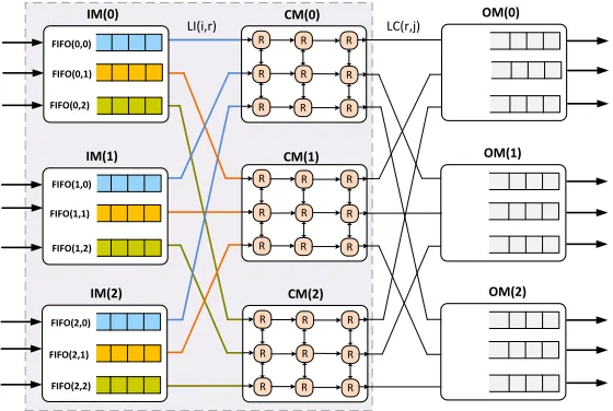
The reference design of a Clos-UDN switch of size (N×N)
is depicted in Fig.2. The key notations used in this paper are listed as in TABLE I. The first stage of the Clos-UDN
comprises k IMs, each of which is of size (n×m). The
. . . . . . IP(0,0) IP(0,n-1) IM(0) . . . IP(i,0) IP(i,n-1) IM(i) . . . IP(k-1,0) IP(k-1,n-1) IM(k-1) CM(0) CM(r) CM(m-1) . . . OP(0,0) OP(0,n-1) OM(0) . . . OP(j,0) OP(j,n-1) OM(j) . . . OP(k-1,0) OP(k-1,n-1) OM(k-1) . . . . . . . . . . . . . . . . . . . . . . . . . . . . . . . . . . . . . . . . . . . . . LI(i,r) LC(r,j) R R ... . . . . . . . . . . . . . . . IP(0,r) IP(i,r) IP(k-1,r) OP(0,h) OP(j,h) OP(k-1,h) . . . . . . . . . FIFO(0,m-1) . . . . . .
m RR Input Schedulers
per IM (k x M) micro RR arbiters
per UDN module
Output queues run
(m + 1) faster than
LC links . . . FIFO(0,0) FIFO(0,r) FIFO(i,0) FIFO(i,r) FIFO(i,m-1) FIFO(K-1,0) FIFO(K-1,r) FIFO(k-1,m-1) . . . . . . . . . . . . . . . . . . . . . . . . . . . . . . . . . . . . . . . . . . . . . . . . . . . . . . . . . . . . . . . . . . . . . . . . . . . R . .. R R ... R . .. R . .. ... R .. . R .. . . . . . . . R R ... .. . R . .. R R ... R . . . R . .. ... R .. . R .. . R R ... .. . R . .. R R ... R . . . R . . . ... R . .. R . .. . . . . . .
Fig. 2: (N×N) three-stage Clos-UDN packet-switch architecture with dynamic dispatching scheme
dimension1 (k×k). The third stage consists of k OMs, each
of which has (m×n) dimension. Although it can be general2,
the proposed Clos-UDN architecture has an expansion factor
m
n = 1, making it aBenes lowest-cost practical non-blocking
fabric. An IM(i) has m FIFOs each of which is associated
to one of the m output links denoted as LI(i, r). An LI(i,
r) is related to an CM(r). Because m =n, each FIFO(i, r)
of an input module, IM(i), is associated to one input port,
IP(i, h), and can receive at most one packet and send at most
one packet to one central module at every time slot. A CM(r)
Input line-cards
with FIFOs Output line-cards
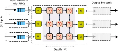
[image:5.612.125.491.66.276.2]Depth (M) (N ) in p u ts NI NI NI R R R R R R R R R NI NI NI
Fig. 3: The UDN crossbar switch
hask output links, each of which is denoted as LC(r,j) and is
connected to OM(j). An OM(j) hasn OPs, each of which is
OP(j,h) and has an output buffer. An output buffer can receive
at most m packets and forward one packet to the output line
at every time slot. Packets destined to different output ports are accepted to the NoC fabric even when some outputs are busy with other packets.
1Unlike conventional Clos-networks, the central modules of the Clos-UDN
can be of size (k×M) crosspoints, whereM refers to the NoC depth and M≤k.
2The Clos-UDN can of course be of any size, wherem≥n. This would
[image:5.612.313.562.350.541.2]simply require packets insertion policy in the FIFOs should we need to maintain low-bandwidth FIFOs. We consider this to be out of the scope of the current work.
TABLE I: The terminologies for the Clos-UDN switch
Notation Description IM(i) (i+1)th
IM at the first stage CM(r) (r+1)th CM at the second stage OM(j) (j+1)thOM at the third stage
i IM number, where0≤i≤k−1
r CM number, where0≤r≤m−1
j OM number, where0≤j≤k−1
h IP/OP number in each IM/OM, respectively, where0≤h≤n−1
IP(i, h) (h+1)thIP at IM(i) OP(j, h) (h+1)thOP at OM(j)
FIFO(i, r) First-In-First-Out queue that stores packets go-ing to CM module,r.
LI(i,r) Output link at IM(i) that is connected to CM(r) LC(r,j) Output link at CM(r) that is connected to
OM(j)
B. NoC based Central Modules
Our reference design is based on the UDN [15] fabric (Fig. 3) that we plug into the Clos central stages. In the Clos-UDN,
every central unit is a two-dimensional mesh (k×k) of small
on-chip packet switched input-queued routers that transport packets across the NoC in a multi-hop fashion. All on-chip routers have small input FIFO queues of variable size (referred
to as Buffer Depth- BD) to store packets on their journey
to their outputs. To avoid elastic buffers, credit-based flow control is used and packets are only sent when buffer space is available [26]. A packet is of fixed-size with relative routing information stored at its header. Packets are fully received and stored in one of the router’s buffers before going to the next hop. Using a deadlock-free NoC routing algorithm, named
[image:5.612.62.293.457.557.2]a rate of one packet per time-slot [19]. We define the speedup of a UDN module as the speed ratio at which the fabric can run with respect to the input/output ports. It is equivalent to the
fabric removing up toSP packets from one input and sending
up to SP packets to one output per time slot. Unlike the
centralized decision making in other multistage packet switch architectures, on-chip routers make local decisions about the packets next destinations using RR arbitration making the scheduling process distributed. The UDN switch can sustain high throughput and low delays under heavy loads if the fabric
is running with a small speedup (SP>1). Given the small sized
on-chip routers and short wires, a speedup of 2 can be readily affordable. Sections VI and IV further study this property.
C. Head of Line Blocking
Common single-hop crossbars experience HoL blocking whenever packets wait in the line cards for their corresponding output ports to be available. These packets block other cells that are queued behind them in the same line card, even though the latter are destined for free output ports [15]. Multi-hop NoC-based crossbars such as the UDN modules, do not suffer the HoL limitation because of the multistage and pipelined nature of the NoC itself. Packets from a single input port heading to different output ports can be accepted into the NoC structure even if their outputs are busy. Moreover, the geometric features of the NoC-based structures (path diversity) and adequate routing methods contribute towards better load balancing. The traffic is parallelized on multiple paths and packets which intend to go to different output ports interfere little with each other. Thus, one can use FIFOs instead of VOQs on the line cards with no severe performance degrada-tion [27].
D. Packets scheduling / dispatching in multistage switches
The need for a conflict-free matching in conventional Clos-network switches, such as MSM, mandates the need of two types of matchings [11] [13] [14]: a matching within each input module to select eligible VOQs among non-empty candidate VOQs and a second matching between IMs and CMs. Both of these matchings are quite complex and time consuming due to the high number of input queues per IM for the first matching as well as the global synchronization of input-output port pairs for IM-CM matching to produce a conflict-free match. Buffers at all stages of an MMM switch absorb the contention and obviates the need for a complex and centralized matching between modules and links of the Clos-network. Larger internal buffers make MMM perform better especially under heavy input loads and bursty traffic. However, modern integrated circuit technology still limits concrete buffered fabrics production. Some proposals suggest pipelined schedulers to manage packets journey in a structure
with b sized crosspoint buffers using rigorous, yet complex
scheduling scheme [3].
The proposed Clos-UDN greatly simplifies the process of packets dispatching and scheduling. First, each IM needs to
maintain only m input queues and each input port of an
input module can send to only one FIFO queue per time-slot, making the FIFO running at only twice the line rate.
In the Clos-UDN switch, there are m input schedulers in
every IM, one per FIFO queue. The RR input schedulers are initialized to different values and they keep updating their selection pointers to one position at the end of every time slot. This guarantees that all pointers are always desynchronized and no conflict in the LI links happens. At the start of
every time-slot, a scheduler selects an LI(i, r) link among
m links in a RR fashion to transfer the HoL packet from
each non-empty FIFO to a central stage/module of the Clos-UDN network. A packet is accepted to the CM module if the left-most NoC router still has room in its left buffer.
Once at the NoC, the”M odulo XY”routing algorithm takes
over and routes the packet to its outgoing port. MMM as described in [3] employs a single central admission scheduler that manages all credit and grant sub-schedulers operating in a pipelined way. Although the suggested scheduler has softer operating time than in MSM architecture, it is more complex than the scheduling scheme the Clos-UDN switch. Schedulers in the line cards send requests to central arbiter. Credit schedulers associated to the switch outputs manage as many credit counters as crosspoints and allocate buffer space for packets. Ultimately, grant schedulers select one among candidate requests and send back a grant signal to the central admission scheduler. Our proposal differs from other types of Clos-network switches with bufferless and buffered middle stages. Mainly, our architecture does not require an IM-CM matching. The central modules, NoC fabrics, make parallel and distributed forwarding decisions independently. Routers of the UDN decide about the next hop of transferred packets. They examine and modify the route information continuously until the packet reaches its destination. Packets contending for a link would remain stored to the router’s buffers before the arbiter grants them access [15] [18]. Correspondingly,
contention for LC(r, j) links gets resolved within the UDN
units as packets progress in the NoC as Fig. 4 shows. Hence, the process of path-allocation in the Clos-network is relaxed and no centralized and global decision and synchronization are needed.
IV. HARDWARE REQUIREMENTS
In this section, we briefly compare the hardware require-ments of the proposed Clos-UDN switch to MSM and MMM switches. CRRD scheduling scheme and its derivatives as adopted for MSM, perform iterative matchings between the set of eligible VOQs and the available LI links. In MMM architecture, packets are selected in a RR manner to move to the available crosspoint buffers before they undergo another selection to be transferred to the output buffers in the OMs. TABLE II compares some features of the three switching architectures.
We mention that a prototype of the UDN crossbar switch has been synthesized in our previous works [18] using an ASIC
65 nm CMOS technology. The synthesis of a (3×3) UDN
switch with no optimization measures achieved 413 MHz with
Tx1
M0 M1 M2 M3
..
. ... ... ...
Disp0
M4
t=0
Fr
o
m
L
I (
i
,
r
)
T
o
L
C
(
r,
j
)
Disp1
Disp2
Disp3
Tx2 Tx1
Tx3 Tx2 Tx1
t=1
t=2
t=3
R
R
R R
R
R R
R
R R
R
R
M0 M1 M2 M4
Tx0
Tx0
Tx0
Tx0
. . . FIFO 0, 0)
FIFO(i, r)
FIFO(k-1, m-1)
. . .
. . . . . .
Dispt+Txt
Txt-1 Txt-2 Txt-3
[image:7.612.120.497.73.211.2]Input module
Fig. 4: Pipelined working of Clos-UDN dispatching and packets forwarding through UDN modules.
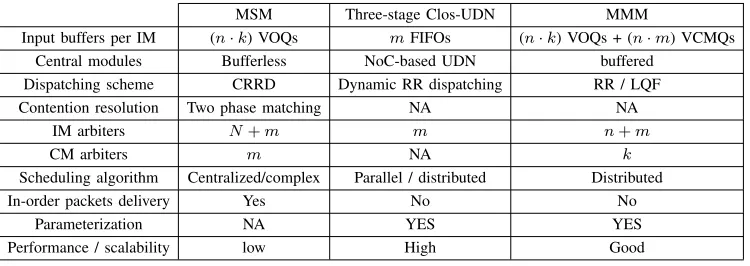
TABLE II: Compare the HW requirements of MSM, MMM and Clos-UDN switches
MSM Three-stage Clos-UDN MMM
Input buffers per IM (n·k) VOQs mFIFOs (n·k) VOQs + (n·m) VCMQs
Central modules Bufferless NoC-based UDN buffered Dispatching scheme CRRD Dynamic RR dispatching RR / LQF Contention resolution Two phase matching NA NA
IM arbiters N+m m n+m
CM arbiters m NA k
Scheduling algorithm Centralized/complex Parallel / distributed Distributed
In-order packets delivery Yes No No
Parameterization NA YES YES
Performance / scalability low High Good
As defined in the same reference, the degree of a router is the number of its I/O ports. The UDN fabric has 3 degree (in the east and west mesh columns) and 4 degree (in the intermediate mesh columns) NoC routers that occupy respectively 0.29
mm2
and 0.38 mm2
. The NIs occupy 0.32 mm2
considering the same synthesis technology [15]. Namely, registers that are used for the routers’ FIFO queues dominate the area. The die area of the circuit is shown to drastically shrink if dedicated hardware rippled-through FIFOs and other CMOS process
technologies are used (e.g. The area of an N = M = 32
switch using CMOS 65 nm process is 403 mm2
and only
134 mm2
if 90 nm CMOS technology is used). Adopting 65
nm CMOS process, a central module of size (8 ×8) used
in a (64 ×64) Clos-UDN network switch would occupy:
0.29×2M+ 0.38(N−2)M+ 0.32×2N ≈224 mm2/CM.
A. Dispatching time
1) MSM with CRRD dispatching: CRRD has two-phase matching process: Matching within IMs and the IM-CM
matching. Phase 1 is an iterative matching that runsitertimes
to maximize the subset of connected VOQs to the
output-links LI(i , r). At every iteration, two RR arbiters are used
as follows: An output link LI(i , r) selects one out of at
most (n.k) requesting VOQs. A VOQ arbiter chooses one
among at most m grants. The resulting complexity in phase
1 is O(iter (log nk))whereiter is the number of iterations
(1≤ iter≤ m). During the IM-CM matching, every LC(r,
j) arbiter chooses one among at most k requests. The time
complexity of this phase is thenO(log k).
2) Packets dispatching in MMM : Arriving packets get
stored in VOQs at the input ports of the MMM3 switch. There
is a total ofN arbiters, one per input port, to select the cell
to send to one of them Virtual CM queues, VCMQs, at the
IMs [28]. The selection of VCMQs is RR based. A total of
m arbiters in each IM are used to perform the selection of
the CM through which the cell is sent. We conclude that the
dispatching complexity is O(log nm)4.
3) Dispatching in the Clos-UDN switch: The dispatching scheme is non-iterative and made of a single phase. At
each cell time, m RR arbiters in the IMs select CMs to
dispatch HoL packets. This makes the complexity time equal to O(log m). The dispatching process and packets routing through the UDN modules work in parallel. The pipelined nature of the UDNs makes the dispatching time at time slot
t(Dispt) and the packets scheduling and forwarding through
the NoC (T xt) overlapping. We call F0, the flow of packets
dispatched to a particular UDN module at time slott= 0. As
depicted in Fig. 4,F0 arrives to the NoC routers of the first
column M0. Forwarding decisions are taken and packets are
transferred to inputs of the next hop. At time slot t = 1, a
new flow of packets F1 arrives to M0 while F0 gets routed
3MMM packet switch architecture as described in [28].
[image:7.612.117.492.263.396.2]to the next stage of the UDN. Solidly connecting the two
first stages of the Clos-UDN switch removes the (k×m)
input schedulers used to dynamically dispatch cells to the central modules. Henceforth, the complexity of the switch is considerably reduced.
B. Hardware complexity for dispatching
1) MSM with CRRD dispatching scheme: Every IM has
m output-link arbiters and N VOQ arbiters. Generally, the
complexity of the RR arbiter isO(log nreq), wherenreq is the
number of requests to be selected by the arbiter. The hardware complexity in case of MSM with CRRD scheme in the IM is O(log mN) [13]. There are also k LC(r, j) arbiters at the central modules each of which selects one request out of at
most krequests. The total complexity of a CM is O(log k).
2) MMM switch: MMM architecture requires many buffers to house packets at every stage of the Clos switch. In addition
to the N VOQs present at the input ports, each IM block is
made of (n·m) VCMQs. The operations of VOQ and VCMQ
selection performed before the packets dispatching to the CMs, make the hardware complexity of an input module of MMM
switch O(log nN). The HW complexity of a CM and OM
are O(log k2
)andO(log nm)respectively.
3) Clos-UDN switch: In Clos-UDN switch, marbiters per
IM are associated to m FIFOs. A queue arbiter selects one
among m CMs to dispatch the current HoL packet which
makes the hardware complexity of an IM equal toO(log m)).
Every CM bloc at the central stage is made of (k×M)
mini-routers. Every on-chip router selects packets in a RR manner to forward them to the next hop. This results into a complexity of O(log kM).
During the first phase of the CRRD matching, requests
are sent to the LI(i, r) arbiters that send back grants to the
selected VOQs. A VOQ arbiter accepts one among the received
grants. The size of the interconnect between m output-links
and (n·k) VOQs arbiters increase with the switch size making
the wiring more complex. The number of crosspoints Nxp
for interconnection wires between the IM arbiters is given
by Nxp =
3
4nkm(nk −1)(m−1) [13]. To diminish the
layout complexity, the CRRD dispatching scheduler needs to be done on multiple-chips [13]. Still, the interconnection between the chips on Printed Circuit Boards (PBCs) and the number of pins in the scheduler chips becomes higher and expensive. Clos-UDN has a simple dispatching scheme and the IM arbiters are not connected to any others which saves the need for complex interconnects. Such a feature makes the Clos-UDN scalable independently of the switch size. The contention resolution in Clos-UDN is progressively resolved as packets advance through the central modules and the implementation complexity is considerably reduced. In [18], a HW implementation of a single-stage UDN packet switch is proposed where it is shown that a UDN module is perfectly feasible considering the current technology and that a cost/performance trade-off can be made by varying the switch parameters and/or the synthesis technology.
C. Average blocking time in the IM queues
We give a simplified estimation of the average waiting time that a packet spends in IMs buffers under the following hy-potheses. Input modules have Bernoulli uniform traffic arrivals
occurring at a rate λ and all queues operate independently
one of the other with uniformly distributed service times. We
denote 1µ, the mean service time andρ=λ
µ, the traffic
inten-sity. Given the above-mentioned approximations, we restrict the system analysis to a single FIFO with unlimited capacity behaving as an M/D/1 queue. Due to the feedback loop around the limited size of buffers of on-chip Mini-Routers (MRs), rise dependencies in the departure process from queues of the IMs. Packets are not dispatched to CMs unless the left-most buffers of the routers in the first column of the UDN have room. Next,
we denote BD the capacity of one buffer located at any of
its ingresses. The probability that a packet gets forwarded to a CM can be expressed as:
Pf wd=Pp (1−Pctr) (1)
wherePpis the probability that a packet is present at the input
FIFO and Pctr is the flow-control probability issued by the
left-most buffer of a MR to a requesting packet. Basically, a feedback-control signal is generated when a packet tries to access a saturated buffer which motivates the following
expression for Pctr:
Pctr = [Pp (1−Pserv)]BD (2)
Pserv is the probability that a packet in one of the MR’s
input buffers is served and ningr is the number of the MR’s
ingresses. Since a RR scheduling is adopted to fairly resolve
contention among the MR’s ingresses,Pserv can be expressed
as Pserv = 1/ningr. Ultimately, we can approximate the
average blocking delay a packet experiences in an input FIFO by:
ωblock=
1 2µ′
ρ
1−ρ
(3)
whereµ′ being the modified input queues service time given
by:
µ′ =P
f wd µ (4)
V. DEALING WITHOUT-OF-SEQUENCE PACKETS DELIVERY
Pure space switching like S3 introduces too much
compe-tition between cells at all stages. They suffer low throughput and have crippled performance. Introducing memories to the network switching fabric has always been the remedy to resolve contention. So far, buffreless architectures need com-plex and expensive matching mechanisms to make the path decision. However, they guarantee ordered packets delivery. In the opposite case, the fully buffered architecture MMM has good performance and simpler scheduling process. Yet, packets experience variable queuing delays in the buffers leading in a mis-sequenced cells transmission [29].
FIFO(0,0)
FIFO(0,2) IM(0)
IM(1)
IM(2)
CM(0)
CM(1)
CM(2)
OM(0)
OM(1)
OM(2)
LI(i,r) LC(r,j)
R R R
R R R
R R R
FIFO(0,1)
FIFO(1,0)
FIFO(1,1)
FIFO(1,2)
FIFO(2,2) FIFO(2,0)
FIFO(2,1)
R R R
R R R
R R R
R R R
R R R
R R R
Fig. 5: Example of a (9×9) Clos-UDN switch with static configuration of the IMs/CMs interconnections.
get serviced with variable delays. In the current work, we choose to alleviate packets from getting mis-sequenced in the first place. Based on the three-stage Clos-UDN switch
archi-tecture, we propose removing the(n×m)input schedulers and
[image:9.612.167.447.65.253.2]put in place a static configuration of the connections between the input FIFOs of IMs and CMs’ ingresses (TABLE III).
TABLE III: HW requirements: Dynamic vs static dispatching in Clos-UDN switch
Three-stage Clos-UDN Two-stage Clos-UDN Dispatching scheme Dynamic RR dispatching Static dispatching
IM arbiters m NA
In-order packets delivery No Yes Performance / scalability High Good
Consequently, the new switching architecture can be viewed as a two-stage network. The intuition behind the two-stage
approach is as follows. It is known that the ”M odulo XY”
algorithm used to route packets inside the UDN modules is a deterministic minimal paths algorithm that ensures that packets of the same flow do follow the same path throughout the NoC fabric. Imposing a static dispatching scheme effectively makes traffic flows routed in order through the whole Clos-UDN network. Unlike previous proposals, no re-sequencing buffers, synchronization signals and complex algorithms are required. Theoretically, a two-stage Clos-network is only re-arrangeably non-blocking. As path relocation is prohibited in practical Clos switches, two-stage architecture becomes blocking and compromises throughput [30]. All the same, two-stage interconnects prove to be interesting mainly for optical switching architectures [10] [22] [31]. The architec-ture improvements from the single-stage baseline are still significant. Although, the two-stage Clos-UDN diminishes the extra switching area per IM/OM pair, it contributes toward reducing the cost/complexity and notably ensuring an ordered packets delivery. The switch is still scalable thanks to the scalable central modules and presents good complexity and performance trade-off for high-radix switches.
VI. PERFORMANCE EVALUATION
We use an event-driven simulator to evaluate the perfor-mance of the three-stage Clos-UDN with a dynamic and a static dispatching schemes. Unless it is mentioned, the switch
size is set to (64×64), the on-chip buffers (BD) are worth of
four packets each and square UDN meshes are considered for
the central stage of the Clos-network(M =k). The simulation
time is106
time slots. In the simulation figures,iterxstands
forxnumber of iterations for the CRRD dispatching algorithm
andSP x means that the on-chip links of the UDN modules
in the Clos-UDN switch run x times faster than the LI/LC
links. As for MMM,xbuf f is the size of the middle stage’s
crosspoint buffers.
We compare the performance of the Clos-UDN switch to the MSM switch architecture with CRRD dispatching as described in [13] (baseline) and MMM as discussed in [10]. Both architectures are compared under various switch sizes and traffic scenarios settings including uniform Bernoulli and bursty as well as non-uniform traffic arrivals. It is important to note that the speedup used in the Clos-UDN is different
than the conventional speedup [32], where SP refers to the
internal switch over-speed factor with respect to the external
line rate. HereSP refers to the over-speed factor ofonlythe
NoC routers inside each UDN central module, excluding the LIs and LCs. Meaning, just like the MSM, the Clos-UDN always sends at maximum one packet per LI/LC link per time slot. Since the Clos-UDN does not use iterations (i.e. time) in its matching, this could be compensated by internally running
the UDN CMs with smallSP values.
A. Clos-UDN vs. MSM and MMM
10 20 30 40 50 60 70 80 90 100 102
101 100 101 102 103 104
Offered Load (%)
A
v
e
ra
g
e
C
e
ll
De
la
y
(
c
e
ll
t
im
e
)
[image:10.612.324.558.68.243.2]CRRD__iter2 CRRD__iter4 Clos UDN__SP1 Clos UDN__SP2 Clos UDN__SP4 MMM__xbuff1 MMM__xbuff16
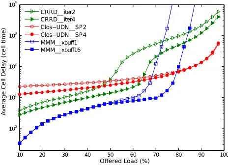
Fig. 6: Delay performance of Clos-UDN, MMM and MSM using CRRD algorithm, Switch size=256, Bernoulli uniform traffic
75 80 85 90 95
101 100 101 102 103 104
Offered Load (%)
Ave
ra
g
e
C
e
ll
D
e
la
y
(ce
ll
ti
me
)
[image:10.612.51.283.68.241.2]CRRD__iter2 CRRD__iter4 Clos UDN__SP1 Clos UDN__SP2 Clos UDN__SP4 MMM__xbuff1 MMM__xbuff16
Fig. 7: Zoomed view of Fig. 6 - Delay performance under high Bernoulli uniform traffic loads
10 20 30 40 50 60 70 80 90 100
100 101 102 103 104
O ered Load (%)
A
v
e
ra
g
e
C
e
ll
De
la
y
(
c
e
ll
t
im
e
)
[image:10.612.325.563.305.479.2]CRRD__iter2 CRRD__iter4 Clos UDN__SP2 Clos UDN__SP4 MMM__xbuff1 MMM__xbuff16
Fig. 8: Delay performance of Clos-UDN, MMM and MSM using CRRD, Switch size=256, Bursty uniform traffic
0 0.1 0.2 0.3 0.4 0.5 0.6 0.7 0.8 0.9 1
0 10 20 30 40 50 60 70 80 90 100
Omega
T
h
ro
u
g
h
p
u
t
Clos UDN__SP1 Clos UDN__SP2 Clos UDN__SP4 MSM__CRRD__iter2 MSM__CRRD__iter4 MMM__xbuff1 MMM__xbuff16
Fig. 9: Throughput stability of Clos-UDN, MSM and MMM, Unbalanced traffic
10 20 30 40 50 60 70 80 90 100
100
101
102
103
Offered Load (%)
Ave
ra
g
e
C
e
ll
D
e
la
y
(ce
ll
time
)
CRRD__iter2 CRRD__iter4 Clos UDN__SP1 Clos UDN__SP2 Clos UDN__SP4
Fig. 10: Delay Performance of Clos-UDN and MSM, Hot-Spot traffic
10 20 30 40 50 60 70 80 90 100
100 101 102 103 104
Offered Load (%)
Ave
ra
g
e
C
e
ll
D
e
la
y
(ce
ll
ti
me
)
256x256__SP1 256x256__SP2 256x256__SP4 64x64__SP1 64x64__SP2 64x64__SP4
[image:10.612.50.282.309.477.2] [image:10.612.328.562.534.713.2] [image:10.612.50.274.536.708.2]Running the CM units at a speedup factor of one makes the
switch achieve 90% throughput. It is the packets progressing
in the central switching units by one at each cycle (SP =
1) that prevents the switch from achieving full throughput.
Increasing the speedup factor to two suffices for the switch to achieve full-throughput. The proposed switch architecture outperforms the MSM under medium-to-high uniform traffic arrivals (which are more relevant in the context of DCNs). The slightly higher delay experienced by the Clos-UDN under light loads is due to the time required to fill-in the pipeline of the multi-hop NoC based CMs as shown in Fig. 4. However, Clos-UDN maintains low and almost constant delay irrespective of the traffic load. When the load is larger than 0.9, the delay
performance of Clos-UDN withSP = 2 becomes better than
MSM using CRRD with 4 iterations and MMM as Fig. 7 shows. We note that increasing the speedup of UDN switches pulls down the cell delay. MMM behavior approaches an OQ switch. It outperforms MSM and Clos-UDN switches if light to medium loads strike the switch inputs. Setting the crosspoint
buffers’ size to b = 1, makes the MMM throughput almost
equal to 94% and full throughput is achieved if the buffers
are as large as b = 16. Clearly, Clos-UDN deals in a better
way with high loads for which it keep the lowest system delay (compared to MSM and MMM, for high loads).
2) Bursty uniform traffic: High-bandwidth demanding ap-plications make the bursty traffic pattern prevalent in a data center network with high-levels of peak utilization. We ex-amine the effect of burstiness on the Clos-UDN switch by considering a bursty traffic with a default burst length equal to 10. Fig. 8 reveals that the delay’s growth of the Clos-UDN under bursty arrivals is smoother than that of the MSM with CRRD even if the matching procedure runs 4 iterations. Increasing the number of iterations for the CRRD provides better matching between IMs and CMs and resolves faster the contention which lead to improved switch performance
when the load is below 0.7. Increasing the SP reduces the
initial delays for the Clos-UDN. Simulations show that MMM is less efficient when evaluated for bursty traffic. Although the switch has lower average packet delay, Clos-UDN with
a minimum SP = 2 proves to outperform both MSM and
MMM under heavy bursty traffic arrivals. Visibly, MMM has degraded throughput and increasing the crosspoint buffers to
b= 16is of little effect as it only shifts the switch throughput
from 77%to86%.
3) Unbalanced traffic: Next, we evaluate the Clos-UDN switch under non-uniform unbalanced traffic, as specified in [13]. This traffic pattern has one fraction of the total load generated uniformly and the other fraction destined to the
output with the same index as the issuing input. If ω = 0,
then the traffic is perfectly uniform. Ifω= 1, the switch deals
with a totally unbalanced traffic. We evaluate the throughput performance of the proposed switch. We reproduce the results for the MMM as described in [10] where the Longest Queue First (LQF) selection at the input ports and RR arbiters in the different modules are used. Fig. 9 depicts the switch
throughput when we vary the unbalancing coefficient ω.
The Clos-UDN with SP = 1 achieves 90% throughput for
ω = 0 (uniform traffic), as has been already shown in
Fig. 6. MMM achieves better throughput than MSM switch
performing CRRD scheduling (60%throughput if 4 iterations
are used and ω = 0.5). However Clos-UDN has higher and
more stable throughput variation than both semi-buffered and
fully buffered architectures under the whole range ofω.
Setting ω = 0.5 corresponds to a non-uniform hot-spot
traffic, where 50% of the input load goes to one output while the rest is equally distributed over the remaining outputs. A further step in analyzing the Clos-UDN switch performance consists on inspecting the average delay under non-uniform traffic pattern in comparison to MSM. Fig. 10 presents the
results, under these settings, for a (64×64) switch operating
both the Clos-UDN and MSM architectures. Curves in Fig. 10 point out that the Clos-UDN switch architecture has much better average delay than the MSM, irrespective of the Clos-UDN speedup and the CRRD number of iterations.
B. Further analysis of the Clos-UDN switch
In this subsection we vary a set of parameters of the Clos-UDN and study the effect of each one on the overall switch’performance.
1) Varying the switch size: Performance curves depicted in Fig. 11 show that increasing the Clos-UDN valency has a minor effect of the overall delay, making it truly a scalable solution and a good alternative for DCN Top-of-Rack switches.
Large switches can achieve good performance if the SP is
increased to just 2. A (256×256) Clos-UDN switch running
at a speed SP = 4 has an average cell latency that is
approximately the same as (64×64) switch withSP = 2.
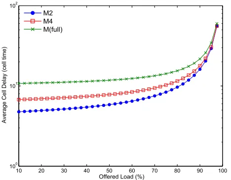
2) Varying the depth of the UDN units: The Clos-UDN is configurable. Changing the number of the UDN’s intermediate
stages (M) can be done to trade-off cost/performance [15]
[18]. However, this cannot be done without limits as it may cause the structure of the NoC to be congested and the performance to collapse. The Clos-UDN’s initial latency is acquired from the multi-hop nature of the NoC-based CMs. In conventional crossbars, packets cross the fabric in one shot.
However, in UDN, they have to cross at least M on-chip
routers to reach their destination which results in a cumulative
delay. Reducing M causes the packets to travel through less
intermediate stages before arriving to LC links. Hence, the average packets latency gets low when the switch is
non-congested for fabrics running at a minimumSP = 2as Fig. 12
shows.
3) Running the central modules faster: As Part of the Clos-UDN architecture, all embedded routers of the CM blocks are input-buffered routers that require speedup to achieve
full-throughput. Fig. 13 shows that increasingSP contributes
toward diminishing the overall latency when the switch is
less congested. Reducing the number of columns M to only
two improves the system's latency under light traffic loads.
Fig. 14 shows that decreasingM is more effective than running
the CMs faster as (increasing SP for a given depth M). We
conclude that running UDN central modules faster for a given
10 20 30 40 50 60 70 80 90 100 100
101 102
Offered Load (%)
Ave
ra
g
e
C
e
ll
D
e
la
y
(ce
ll
ti
me
)
[image:12.612.51.285.56.238.2]M2 M4 M(full)
Fig. 12: Impact of the UDNs’ mesh depth on the delay performance of the Clos-UDN switch, Bernoulli Uniform traffic,
SP = 2
10 20 30 40 50 60 70 80 90 100
100 101 102 103
Offered Load (%)
Ave
ra
g
e
C
e
ll
D
e
la
y
(ce
ll
ti
me
)
SP1 SP2 SP3 SP4
Fig. 13: Impact of the speedup on the delay performance of the Clos-UDN switch, Bernoulli traffic
10 20 30 40 50 60 70 80 90 100
100 101 102 103 104
Offered Load (%)
Ave
ra
g
e
C
e
ll
D
e
la
y
(ce
ll
ti
me
)
[image:12.612.324.563.60.240.2]M2__SP2 M2__SP4 M(full)__SP2 M(full)__SP4
Fig. 14: Impact of the speedup SP and mesh depth M on the Clos-UDN switch latency, Bursty traffic
10 20 30 40 50 60 70 80 90 100
100 101 102 103 104
Offered Load (%)
A
v
e
ra
g
e
C
e
ll
D
e
la
y
(c
e
ll
ti
m
e
)
Static__SP1 Static__SP2 Static__SP4
Dynamic__SP1
Dynamic__SP2 Dynamic__SP4
Fig. 15: Delay performance of the two-stage Clos-UDN switch, Bernoulli uniform traffic
and that one can choose the best settings for the Clos-UDN architecture to achieve pre-estimated performance levels.
4) Changing the Buffer Depth : A single router in a UDN module is a complete switching element with small input memories and a processing unit. Input buffers account for the major part of a router's area which needs to be as small as
possible for cost saving reasons. Increasing theBD improves
the system latency, but reducing the buffering amount can produce problems related to insufficient buffering [14].
C. Performance of the two-stage Clos-UDN switch
Simulations are done for a (64 × 64) switch with full
depth (M = k) and a variable speedup factor. In this
sub-section, we use the terminology Dynamic and Static to present the Clos-UDN performance with respectively a dynamic RR dispatching scheme and a static packets dispatching process. There are many ways to configure the first two stages connec-tions. We choose to keep the default Clos interconnection as
Fig.5 depicts. Considering a directional traffic, themoduloXY
algorithm would work as following: All packets that come
from an input FIFO(i, r) heading to OP(i, h) are always
forwarded to the ingress i of CM(r) via LI(i, r). Resolving
the packets destination would result in a direct route across the UDN fabric (the route from an input to an output of the NoC mesh with no turns). In case of crossing traffic, where
packets stored in FIFO(i, r) are destined to OP(j, h) (j 6=i),
the load is distributed in the UDN fabric and forwarded using
different paths to the right LC(r, j).
[image:12.612.329.564.290.476.2] [image:12.612.53.288.294.474.2]10 20 30 40 50 60 70 80 90 100 101
102 103
Ave
ra
g
e
C
e
ll
D
e
la
y
(ce
ll
time
)
Static__SP1 Static__SP2 Static__SP4
Dynamic__SP1 Dynamic__SP2 Dynamic__SP4
[image:13.612.326.556.66.236.2]Offered Load (%)
Fig. 16: Delay performance of the two-stage Clos-UDN switch, Bursty uniform traffic
10 20 30 40 50 60 70 80 90 100
101 10
Offered Load (%)
Ave
ra
g
e
C
e
ll
D
e
la
y
(ce
ll
ti
me
)
2
Static__SP1 Static__SP2 Static__SP4
[image:13.612.52.281.67.243.2]Dynamic__SP1 Dynamic__SP2 Dynamic__SP4
Fig. 17: Delay performance of the two-stage Clos-UDN switch, Hot-Spot traffic
80 82 84 86 88 90 92 94 96 98 100
101 102
Offered Load (%)
A
ve
ra
g
e
C
e
ll
D
e
la
y
(c
e
ll
tim
e
)
Static__SP2 Static__SP4 Dynamic__SP1 Dynamic__SP2 Dynamic__SP4
Fig. 18: Zoomed view of Fig. 17 - Delay performance under high Hot-Spot traffic loads
0 0 0 0 0 0 0 0 0 0 1
0 55 0 65 0 75 0 85 0 95
S S
S S
S S
Dynamic__SP1 Dynamic__SP2 Dynamic__SP4
T
h
ro
u
g
h
p
u
t
[image:13.612.325.560.292.482.2]Omega
Fig. 19: Throughput stability of the two-stage and three-stages Clos-UDN under Unbalanced traffic
for a throughput degradation that we clearly notice when the
central switching modules are run at SP = 1. Speeding up
the CMs preserves the switch throughput and SP ≥2 makes
the two-stage Clos-UDN achieve performance comparable to that of a three-stage Clos-UDN switch using a RR packets dispatching.
Likewise, we simulated the two-stage switch with different
SP values under the uniform bursty traffic. The bursty traffic
can be modulated as an an on-off Markov process, where the average burst length is set to 10. Fig. 16 shows that the
Clos-UDN with with static configuration andSP = 2provides 50%
throughput. Setting SP to 4 makes the switch reach a delay
performance little higher than the switch with a dynamic RR dispatching.
b) Unbalanced traffic: The unbalanced traffic is defined
using an unbalanced coefficient ω that reflects the
propor-tionality of the traffic distribution among the outputs. For an
(N×N) switch, we define the traffic load from an input port
sto an output portdbyρs,d, where
ρs,d = (
ρ(ω+1−ω
N ) ifs=d
ρ1−ω
N otherwise
Fig. 17 shows that using a speedup of one, the two-stage
switch reaches up to 87% throughput. Making SP ≥ 2
proves to be sufficient in the sens that it makes the statically configured switch achieve full throughput. We note that for high traffic loads, the average cell delay of the two-stage switch becomes better than the three-stage Clos-UDN with dynamic packets dispatching as depicted in Fig. 18.
[image:13.612.53.287.294.481.2]0 5 10 0 5 10 12.49
125 1251
Row Fu lly Unbalanced traffic
Column P o P 5 1 5 1
62
625 63
Row
UniformBernou lli traffic
Column P o P 5 1 5 1
62
625
63
Row Column
P
o
P
12!495 12"5 12#5$5
6%22 6&24 6'26
6(24 6)26 6*28
+ 2 4 6
+ 1 2 3 4 5 6 7 Row C o lu m n
+ 2 4 6
+ 1 2 3 4 5 6 7 Row C o lu m n
, 2 4 6
, 1 2 3 4 5 6 7 Row C o lu m n
Uniform-/ r12y traffic
3-/ r124ength=15)
6 5 17 8 5 19 12:49 12;5
12<51
Row > ? @ @y UnAa@anced traffic
Column P o P C 5 1D E 5 1G 12
12H5 13
Row
UniformIernoJKKi traffic
Column P o P L 5 1M N 5 1O 6P1 6Q2
6R3
6T4
Row
Uniform-/r1 2y traffic
3-/r124ength=15)
Column
P
o
P
12U495 12V5 12W5X5
12Y2 12Z4 12[6 12\8
6]2 6^25 6_3
` 2 4 6
` 1 2 3 4 5 6 7 Row C o lu m n
a 2 4 6 a 1 2 3 4 5 6 7 Row C o lu m n
c 2 4 6
c 1 2 3 4 5 6 7 Row C o lu m n
Dynamic di
sdat
e fin
ise feme
[image:14.612.131.481.65.483.2]Static di
at
in
eme
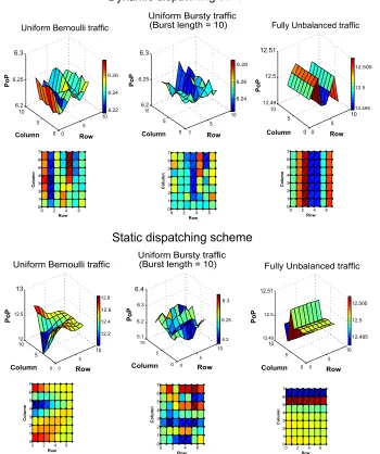
Fig. 20: Propotion of Packets moving west-east in the middle-stage UDNs
static scheme makes the load partition between CMs strongly dependent on the traffic type. If the switch is fed with skewed traffic, some LI links (and consequently UDNs) might be loaded. We intercept packets exiting the Clos-UDN switch and analyze the Proportion of Packets (PoP) going over East links of the of the UDN’ mini-routers. Fig. 20 illustrates the average
PoP of the West-East traffic calculated over 8 UDNs (in a
(64×64) Clos-UDN switch operating with UDN SP = 2).
We note that packets get equally distributed among East links for both dispatching schemes under uniform traffic arrivals and
that for a critical diagonal traffic (where inputiof the switch
sends traffic only to output of the same index), the dynamic RR dispatching contributes to better load distribution in the UDN modules.
c) Throughput stability in the two-stage Clos-UDN:
Limiting the speedup factor to SP = 1, limits the switch
performance under a non-uniform traffic using both static and dynamic dispatching methods. The UDN fabrics being tanked
with arriving packets cannot afford full throughput with a
SP = 1. Slightly increasing the UDNs speedup enhances the
switch performance and SP = 2 makes the two-stage
Clos-UDN reach 100%throughput under the complete range of ω
as Fig. 19 depicts.
VII. CONCLUSION
In this paper, we propose a novel multistage switching archi-tecture for Data Center Networks. The Clos-UDN is a highly-scalable and easily configurable switch with simple FIFO queuing at the input modules and simple packets dispatching schemes. We plug NoC-based fabric modules with on-chip buffering and arbitration in the middle stage of the Clos-network. The NoC switches, allow a pipelined and distributed scheduling and obviate the need for a centralized and complex arbiter as it is the case for bufferless and semi-buffered
architectures (Concurrent dispatching for S3switch and CRRD
large crosspoint buffers like those that fully buffered structures require (MMM switch).
We present and discuss the performance of two possible packets dispatching schemes. The Clos-UDN switch with a dynamic dispatching process mis-sequences packets delivery in the same way MMM does. We observe that it is possible to prevent packets from getting dis-ordered at first place by introducing a static configuration of the IM and CM modules interconnections. Although this reduces the switch architecture to two-stage Clos-network, this approach results in constantly dispatching packets of a given flow to the same CMs where they get forwarded in-order and in a multi-hop way until their output ports using deterministic routes.
Our extensive and detailed simulations show that the three-stage Clos-UDN provides high and stable throughput.
Con-sidering a minimum SP= 2, the proposed switch gives good
average latency as compared to MSM and MMM switches under different traffic loads with far less complex architec-ture and scheduling process. The Clos-UDN demonstrates: 1) a robustness of packet delay to the switch valency; 2) an immunity of overall delay in presence of hotspots; 3) almost constant delay variation under medium-to-high loads no matter the switch size and the traffic type are and 4) high achievable throughput. Based on our previous works and the current technology advances, we conjecture that running the switch central modules (UDNs) with speedup of two is quite straightforward. The HW implementation and prototyping of the Clos-UDN switch are reserved for future work.
VIII. ACKNOWLEDGMENT
This work was supported by the EU Marie Curie Grant (SCALE: PCIG-GA-2012-322250).
REFERENCES
[1] “Cisco,” 2016. [Online]. Available: http://www.cisco.com/c/en/us/ products/switches/nexus-5000-series-switches/datasheet-listing.html [2] N. I. Chrysos, “Request-Grant Scheduling for Congestion Elimination
in Multi-Stage Networks,” Crete University, 2006, Tech. Rep. [3] N. Chrysos and M. Katevenis, “Scheduling in Non-Blocking Buffered
Three-stage Switching Fabrics.” inINFOCOM on, vol. 6, 2006, pp. 1– 13.
[4] H. J. C. Yu Xia, “On Practical Stable Packet Scheduling for Bufferless Three-stage Clos-network switches,” inHPSR. IEEE, 2013, pp. 7–14. [5] “Dell,” May 2016. [Online]. Available: http://i.dell.com/sites/doccontent/
shared-content/data-sheets/en/Documents/Dell Networking S4048T ON Spec Sheet.pdf
[6] “Juniper Networks,” June 2015. [Online]. Available: http://www.juniper. net/assets/us/en/local/pdf/datasheets/1000414-en.pdf
[7] C. Clos, “A Study of Non-Blocking Switching Networks,”Bell System Technical Journal on, vol. 32, no. 2, pp. 406–424, 1953.
[8] H. J. Chao, J. Park, S. Artan, S. Jiang, and G. Zhang, “TrueWay: A Highly Scalable Multi-plane Multi-stage Buffered packet switch,” in HPSR. IEEE, 2005, pp. 246–253.
[9] E. Oki, N. Kitsuwan, and R. Rojas-Cessa, “Analysis of Space-Space-Space Clos-network packet switch,” inICCCN. IEEE, 2009, pp. 1–6. [10] Z. Dong, R. Rojas-Cessa, and E. Oki, “Memory-Memory-Memory Clos-network packet switches with In-sequence Service,” inHPSR. IEEE, 2011, pp. 121–125.
[11] F. M. Chiussi, J. G. Kneuer, and V. P. Kumar, “Low-cost Scalable switch-ing solutions for broadband networkswitch-ing: the ATLANTA architecture and Chipset,” Communications Magazine on, vol. 35, no. 12, pp. 44–53, 1997.
[12] X. Li, Z. Zhou, and M. Hamdi, “Space-Memory-Memory architecture for Clos-network packet switches,” inICC. IEEE, 2005, pp. 1031–1035.
[13] E. Oki, Z. Jing, R. Rojas-Cessa, and H. J. Chao, “Concurrent Round-Robin-based Dispatching schemes for Clos-network switches,” IEEE/ACM on, vol. 10, no. 6, pp. 830–844, 2002.
[14] J. Kleban and A. Wieczorek, “CRRD-OG: A packet Dispatching algorithm with Open Grants for Three-stage Buffered Clos-network switches,” inHPSR. IEEE, 2006, pp. 6–pp.
[15] K. Goossens, L. Mhamdi, and I. V. Senin, “Internet-router Buffered Crossbars based on Networks on Chip,” in DSD. IEEE, 2009, pp. 365–374.
[16] E. Bastos, E. Carara, D. Pigatto, N. Calazans, and F. Moraes, “MOTIM-A Scalable “MOTIM-Architecture for Ethernet switches,” inISVLSI. IEEE, 2007, pp. 451–452.
[17] F. Moraes, N. Calazans, A. Mello, L. M¨oller, and L. Ost, “HERMES: An Infrastructure for Low Area overhead packet-switching Networks on Chip,”INTEGRATION, the VLSI journal on, vol. 38, no. 1, pp. 69–93, 2004.
[18] T. Karadeniz, L. Mhamdi, K. Goossens, and J. Garcia-Luna-Aceves, “Hardware Design and Implementation of a Network-on-Chip based load balancing switch fabric.” inReConFig., 2012, pp. 1–7.
[19] L. Mhamdi, K. Goossens, and I. V. Senin, “Buffered Crossbar Fabrics Based on Networks on Chip.” inCNSR., 2010, pp. 74–79.
[20] A. Bitar, J. Cassidy, N. E. Jerger, and V. Betz, “Efficient and Pro-grammable Ethernet switching with a NoC-enhanced FPGA,” in Pro-ceedings of the 10th ACM/IEEE ANCS. ACM, 2014, pp. 89–100. [21] F. Hassen and L. Mhamdi, “A Multi-Stage Packet-Switch Based on NoC
Fabrics for Data Center Networks,” inGlobecom Workshops. IEEE, 2015, pp. 1–6.
[22] I. Keslassy and N. McKeown, “Maintaining Packet Order in Two-Stage switches,” in INFOCOM. 21st Annual Joint Conference of the IEEE Computer and Communications Societies on, vol. 2. IEEE, 2002, pp. 1032–1041.
[23] Z. Dong, R. Rojas-Cessa, and E. Oki, “Buffered Clos-network Packet Switch with per-output flow queues,” Electronics letters on, vol. 47, no. 1, pp. 32–34, 2011.
[24] C.-S. Chang, D.-S. Lee, and Y.-S. Jou, “Load balanced Birkhoff-Von Neumann switches,” inHPSR Workshop. IEEE, 2001, pp. 276–280. [25] R. Roberto and C. Lin, “Scalable Two-stage Clos-network Switch and
Module-First Matching,” inHPSR Workshop., 2006, pp. 6–11. [26] K. Goossens, J. Dielissen, and A. Radulescu, “Æthereal Network on
Chip: Concepts, Architectures, and Implementations,”Design & Test of Computers on, vol. 22, no. 5, pp. 414–421, 2005.
[27] A. Radulescu, J. Dielissen, S. G. Pestana, O. P. Gangwal, E. Rijpkema, P. Wielage, and K. Goossens, “An Efficient On-Chip NI Offering Guaranteed Services, Shared-Memory Abstraction, and Flexible Net-work Configuration,”IEEE Transactions on Computer-Aided Design of Integrated Circuits and Systems, vol. 24, no. 1, pp. 4–17, 2005. [28] Z. Dong and R. Rojas-Cessa, “Non-blocking Memory-Memory-Memory
Clos-network packet switch,” inSarnoff Symposium, 34th IEEE. IEEE, 2011, pp. 1–5.
[29] S.-T. Chuang, S. Iyer, and N. McKeown, “Practical Algorithms for Performance Guarantees in Buffered Crossbars,” in INFOCOM. 24th Annual Joint Conference of the IEEE Computer and Communications Societies on, vol. 2. IEEE, 2005, pp. 981–991.
[30] W. Song, D. Edwards, J. Garside, and W. J. Bainbridge, “Area Efficient Asynchronous SDM routers using 2-stage Clos switches,” in Proceed-ings of the Conference on Design, Automation and Test in Europe. EDA Consortium, 2012, pp. 1495–1500.
[31] C.-S. Chang, D.-S. Lee, and Y.-S. Jou, “Load balanced Birkhoff-Von Neumann switches, part i: one-stage buffering,”Computer Communica-tions on, vol. 25, no. 6, pp. 611–622, 2002.
Fadoua HASSEN received her M.S. degree in Telecommunications Communication engineering (with distinction) from the Higher School of Com-munication of Tunis, SUP’COM University of Carthage, in 2011. She is currently working towards the Ph.D degree in Electrical Engineering at the Uni-versity of Leeds. Her research interests include high-performance packet-switch design, scalable switch-ing architectures and switchswitch-ing/routswitch-ing in Data Cen-ter Networks. She is a student member of the IEEE.
Lotfi MHAMDI received the Master of