The Development of Novel Surface Modifications for
use in a Skeletal Regeneration System
Thesis submitted in accordance with the requirements of the University of
Liverpool for the degree of Doctor in Philosophy by
Sandra Fawcett
Page ii
Acknowledgements
I would like to thank my supervisors:
Prof. John Hunt, for allowing me to pursue this PhD and being sufficiently tough on me to make me able to achieve my goal.
Dr Judith Curran for everything from day to day supervision and confocal microscopy to shopping trips!
Dr Nick Rhodes for our last minute meetings and guidance with my write up, and interesting chats. Their help, support and guidance, during this work has been essential and I really can't express my gratitude.
I would like to thank Prof. Gallagher, and his team Jane, Pete and Craig for allowing me to use their laboratory and sourcing some primary tissue for cell isolation. Thanks!
I would like to thank my collaborators Dr.Lloyd Hammilton, and Prof.Kevin Shakeshef and Prof. Alexander Morgan for all the help regarding the plasma modifications and injectable system. I also need to thank Dr Mark Murphey for help with AFM.
I have a lot of people to thank, my friends from clinical engineering past and present, Katie, Fiona, Shirl, Lyndsey, Nick, Theun, Mick, Rui, Fanrong....thanks for being encouraging and wonderful people to work with. This whole thing was so much more fun because of you all.
I would also like to thank my new colleges in Clinical and Molecular Pharmacology.
To my emergency support team (Mum, Dad, Jenny and Bill) for being there to offer love support and emergency child care!
Page iii
Contents
Chapter 1 Introduction
1.1 The Principles of Regenerative Medicine 1
1.2 Bone Fracture 1
1.3 Non Union Bone Fracture 2
1.4 Normal Bone Healing Pathway 4
1.5 The Formation of a Cartilaginous Callus 5
1.6 The in vivo Osteogenic Differentiation Pathway of
Mesenchymal Stem Cells 7
1.7 Current Therapy for Bone Loss in Non Union Fracture 9
1.8 Synthetic Bone Grafts 11
1.9 The Ideal Bone Biomaterial 12
1.10 Mesenchymal Stem Cells 13
1.11 The Identification and Profile of Mesenchymal
Stem Cells 15
1.12 Differentiation of Mesenchymal Stem Cells 17
1.13 Cell Delivery Systems for Bone Regeneration 18
1.14 Polymers as Cell Delivery Systems 19
1.15 Surface Modifications 22
1.16 Modifications for Cellular Interactions to Mimic the
Extracellular Matrix (ECM). 23
Page iv
1.18 Chemical Modification 25
1.19 Amine Groups 26
1.20 Methyl Groups 27
1.21 Hydroxyl Groups 27
1.22 Carboxyl Groups 28
1.23 Plasma Modification Techniques 28
1.24 Silane Modification Techniques 29
1.25 The Characterisation of Surface Modifications 30
1.26 Water Contact Angle 30
1.27 SEM (Scanning Electron Microscopy) 31
1.28 AFM (Atomic Force Microscopy) 31
1.29 XPS (X-ray Photoelectron Spectroscopy) 32
1.30 Specific Chemical Assays - Ninhydrin 32
1.31 Topography vs Chemistry 33
1.31 2D to 3D 34
1.32 Cell Responses in 3D Cultures 35
1.33 The Ideal Bone Regeneration System 35
1.34 Hypothesis 36
Page v
Chapter 2 Methods and Materials
2.1 Methods for Chapter 3; PLGA scaffold construction and analysis 45
2.1.1 Manufacture of Materials: The two component injectable system 45
2.1.2 Manufacture of PLGA sphere 45
2.1.3 PLGA adhesive 45
2.1.4 Material Modification of PLGA spheres 46
2.1.5 Water contact angle measurement 46
2.1.6 SEM of materials 47
2.1.7 X-ray Photoelectron Spectroscopy (XPS) 47
2.1.8. Culture of Mesenchymal stem cells (MSC) 48
2.1.9 Mesenchymal stem cell culture with 3D scaffolds. 49
2.1.10 Sample preparation for LDH Assay 50
2.1.11 LDH Assay 51
2.1.12 Histology 51
2.1.13 Fixation 51
2.1.14 Embedding of Samples in Glycolmethacrylate (GMA) Resin 51
2.1.15 Sectioning 52
Page vi
2.1.17 Van Gieson Stain 53
2.1.18 Von Kossa Stain 54
2.1.19 Alcian Blue Stain 54
2.1.20 Alizarin Red Stain 55
2.1.21 Cryo SEM Examination of Cellular Samples 55
2.1.22 MSCs on 3D Scaffold Prepared with Multiple Layers
of Modification 56
2.2 Methods for Preparation and Analysis of Silane
Modified Borsilicate Glass 59
2.2.1 Preparation and Modification of Borsilicate Glass 59
2.2.2 Atomic Force Microscopy (AFM) 59
2.2.4 Ninhydrin on Films and Glass 59
2.2.5 WCA Measurements 60
2.2.6 Material Modification and PBS Interaction 60
2.2.7 Von Kossa Stain 61
2.2.8 X-ray Analysis of Glass and Films 61
2.2.9 Culture of Mesenchymal Stem Cells (MSC) 62
Page vii
2.2.11 Von Kossa Staining of Coverslips 63
2.2.12 SEM 63
2.2.13 Preparation of RNA using Trizol 64
2.2.14 rt-PCR 65
2.2.15 Immunostaining for Confocal Microscopy 66
2.2.16 Isolation of Primary Human Osteoblast-like Cells 67
2.2.18 Primary Human Osteoblasts-like Cells on Silane
Modified PLGA Films 68
2.2.19 Von Kossa Staining of Human Osteoblast Samples 69
2.2.20 SEM of Primary Human Osteoblast Samples 69
2.2.21 Nodule Count and Measurement 69
2.2.22 rt-PCR of Osteoblast like Cells 69
2.3 Preparation and Silane Modification of PLGA Films and Spheres 69
2.3.2 PLGA (85:15mw) Film Production and Modification 69
2.3.3 AFM Microscopy 70
2.3.4 Ninhydrin on Films and Glass 71
2.3.5 Preparation of Double Sided Materials for WCA 71
Page viii
2.3.7 SEM of Modified Films 72
2.3.8 Application of Mesenchymal Stem Cell to Modified PLGA Films 72
2.3.9 Von Kossa Staining of Coverslips 72
2.3.10 Sphere Manufacture for Silane Modifications 72
2.3.11 Silane Modification of Spheres 73
2.3.12 Ninhydrin Assay of Modified Spheres 73
2.3.13 SEM of PLGA Spheres 74
2.3.14 MSC on PLGA System 74
2.3.15 Histology 74
2.3.16 Fixation 74
2.3.17 Embedding of Samples in Glycomethacrylate Resin 75
2.3.18 Sectioning 75
2.3.19 H and E Stain 75
2.3.20 Van Geison Stain 75
2.3.21 Von Kossa Stain 76
2.3.22 Alcian Blue Stain 76
2.3.24 Alizarin Red Stain 76
Page ix
Page x
Chapter 3 Plasma Modification Results
3.1Introduction for Plasma Pesults 77
3.2 Water Contact Angle of Modified Materials 80
3.3 SEM of modified Spheres 82
3.4 X-ray Photoelectron Spectroscopy (XPS) 84
3.5 Cryo SEM of Mesenchymal Stem Cells on Plasma
Treated 3D Scaffolds 87
3.6 LDH Assay to Detect Cell Number on 3D Scaffold 89
3.7 Histological Analysis of Plasma Treated Scaffolds 93
3.8 Histological Analysis of Dual and Triple Modifications 99
3.9 Discussion of Plasma Modification Results 101
3.10 Discussion of Dual and Triple Modification Results 103
Chapter 4 Silane Modifications on Glass Substrate
4.1 Surface Characterization of Silane Modified Glass using
AFM Microscopy 110
4.2 Ninhydrin Assay of Silane Modified Borosilicate Glass 115
4.3 Dynamic Water Contact Angle of Silane Modified Borosilicate Glass
(advancing angle) 120
4.4 Interaction of Silane Modified Surfaces with Phosphate Buffered
Saline Solutions of Varying Concentrations 120
4.5 X-ray Microanalysis of Surfaces After PBS Exposure for 7 days 120
Page xi Glass after 7, 14 and 28 days Incubation, Stained with Von Kossa’s
Stain for Mineralisation. 124
4.7 SEM Investigation of Human Mesenchymal Stem Cell Interactions
with Silane Modified Glass after 7, 14 and 28 days Incubation 129
4.8 Real time Polymerase Chain Reaction (rt PCR) Investigation
into Human Mesenchymal Stem Cell Interactions with Silane Modified
Glass after 7, 14 and 28 days Incubation. 134
4.9 Confocal Microscopy Investigation into Human Mesenchymal
Stem Cell Interactions with Silane Modified Glass after 7, 14
and 28 days Incubation. 139
4.10 The Interaction of Primary Human Osteoblast like Cells with Silane
Modified Glass for 7, 14 and 28 days, Stained with Von Kossa’s
Stain for Mineralisation. 144
4.11 Investigation of the Number of Nodules Formed by Primary Human
Osteoblast-like Cells after 7, 14 and 28 days Incubation with Silane
Modified Glass 149
4.12 Investigation of the Size of Nodules Formed by Primary Human
Osteoblast-like Cells after 7, 14 and 28 days Incubation with
Silane Modified Glass. 152
4.13 SEM Investigation of Primary Human Osteoblast-like cells after 7, 14
and 28 days Incubation with Silane Modified Glass 153
Page xii Primary Human Osteoblast-like Cells after 7, 14 and 28 days
Incubation with Silane Modified Glass. 160
4.15 Discussion of Silane Modifications on Glass. 165
Chapter 5 Results: Mesenchymal Stem Cell Response to the Silane
Modification of PLGA Films and Injectable 3D System
5.1 AFM Microscopy of Flat PLGA Films 179
5.2 Ninhydrin Assay of Flat PLGA Films 185
5.3 Dynamic Water Contact Angle of Flat PLGA Films 187
5.4 SEM Microscopy of Flat PLGA Films 189
5.5 Light Microscopy of Flat PLGA Films Seeded with Mesenchymal
Stem Cells and Stained with Von Kossa’s Stain for Mineralisation 192
5.6 Ninhydrin Assay to Determine the Concentration of Amine Groups
Deposited onto Spheres During Silanisation. 198
5.7 Histological Examination of Silane Treated Spheres Incorporated
into the PLGA System Highlighted in Chapter 3. 199
5.8 LDH Assay to Determine Cell Number on PLGA System after 7, 14
and 28 day Incubation with Human Mesenchymal Stem Cells. 205
5.9 Discussion of the Transfer of Silane Modifications onto
PLGA Films and Spheres and the Subsequent Cellular Responses. 207
Chapter 6 Summary Discussion and further work
Page xiii
Chapter 7 Conclusion
7.1 Conclusions for Plasma Modifications on PLGA System 244
7.2 Conclusions Silane Modifications on Glass 244
7.3 Conclusions for Silanes on PLGA Films 245
Page xiv
List of Figures
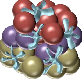
2.1 Diagram of layered surface modified spheres in scaffold, red spheres depict amine modified
surface, purple spheres depict hexane modified surface and gold spheres depict alllyl alcohol modified spheres.
3.1 The two phase injectable scaffold. Red spheres carry the chemical modification and the amorphous shapes represent the adhesive component
3.2 Water contact angle of modified PLGA to measure changes in surface energy. Modified
spheres were compacted into cakes (n=10). Starred bars indicate level of significance as determined by ANOVA and Tukey statistical tests * represent the level of significance (* p=<0.05, ***p=<0.01)
3.3 Water contact angle of modified PLGA to measure changes in surface energy. Modified
spheres were compacted into cakes (n=10). Starred bars indicate level of significance as determined by ANOVA and Tukey statistical tests * represent the level of significance (* p=<0.05, ***p=<0.01)
3.4 X-ray photoelectron spectroscopy (XPS) Spheres were treated with the plasma polymer deposition system and spectra of the modified spheres and an untreated control were taken (n=6). The labelled spectra are typical examples of the spectra taken and refer to the following modifications (a)Hexane, (b) allyl amine, (c) allyl alcohol, (d) acrylic acid, and (e) Unmodified spheres and show the presence of chemistry specific bonds (outlined on spectra).
Page xv 3.6 LDH assay analysis of cell number on modified scaffolds. Scaffolds were seeded with MSC for 14 and 28 days, and an LDH assay was conducted on the modified and untreated scaffolds after maceration at
these timepoints
3.7 :Histological analysis of allyl amine-treated scaffolds. Scaffolds were cultured with MSCs for 28 days, histologically processed and stained with (a) Von Kossa for mineralization, (b) Alizarin red for mineralization, (c) Van Geison for collagen, (d)H and E for cellular morphology and density and (e)Alcian blue for gylosaminoglycan
3.8 Histological analysis of hexane-treated scaffolds. Scaffolds were cultured with MSCs for 28
days, histologically processed and stained with (a) Von Kossa for mineralization, (b) Alizarin red for mineralization, (c) Van Geison for collagen, (d)H and E for cellular
morphology and density and (e)Alcian blue for gylosaminoglycan3.9 Histological
analysis of acrylic acid-treated scaffolds. Scaffolds were cultured with MSCs for 28 days, histologically processed and stained with (a) Von Kossa for mineralization, (b) Alizarin red for mineralization, (c) Van Geison for collagen, (d)H and E for cellular morphology and density and (e)Alcian blue for gylosaminoglycan
3.10 : Histological analysis of allyl alcohol-treated scaffolds. Scaffolds were cultured with
MSCs for 28 days, histologically processed and stained with (a) Von Kossa for
mineralization, (b) Alizarin red for mineralization, (c) Van Geison for collagen, (d)H
and E for cellular morphology and density and (e)Alcian blue for gylosaminoglycan
3.11 Histological analysis of untreated scaffolds. Scaffolds were cultured with
MSCs for 28 days, histologically processed and stained with (a) Von Kossa for
mineralization, (b) Alizarin red for mineralization, (c) Van Geison for collagen, (d)H
and E for cellular morphology and density and (e)Alcian blue for
gylosaminoglycan3.12Images from dual and triple scaffold modifications. Allyl
Page xvi scaffold (dual modification) and allyl amine, hexane and allyl alcohol were
compacted into three layers of the same scaffold (triple modification). The scaffolds
were processed and stained using alizian red and alcian blue. (a)Alcian blue stain of
triple modification scaffold, (b) Alizian red of triple modification scaffold, (c) Alcian
blue of dual modification, (d) Alizarin red of dual modification, (e) Alizarin red stain
of single allyl amine modified scaffold, (f) Alcian blue stain of single allyl amine
modified scaffold, (g) Alizarin red of single allyl alcohol modified scaffold, and (h)
Alcian blue single modification allyl alcohol scaffold
4.1.1 AFM micrograph of untreated borosilicate glass. 12mm diameter glass coverslips were cleaned as stated in protocol. AFM images taken from 5 areas per sample, representative image shown
4.1.2 AFM image of borosilicate glass treated with CL3. 12mm diameter glass coverslips were
cleaned as stated in protocol, and modified using oxygen plasma, then the CL3 silane. AFM images taken from 5 areas per sample, representative image shown
4.1.3 AFM micrograph or borosilicate glass treated with CL4. 12mm diameter glass coverslips
were cleaned as stated in protocol, and modified using oxygen plasma, then the CL4 silane.
AFM images taken from 5 areas per sample, representative image shown4.1.4 AFM
Page xvii 4.1.5 AFM micrograph of borosilicate glass treated with CL7. 12mm diameter glass coverslips
were cleaned as stated in protocol, and modified using oxygen plasma, then the CL7 silane. AFM images taken from 5 areas per sample, representative image shown
4.1.6 AFM micrograph of borosilicate glass treated with CL11. 12mm diameter glass coverslips
were cleaned as stated in protocol, and modified using oxygen plasma, then the CL11 silane. AFM images taken from 5 areas per sample, representative image shown
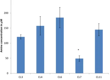
4.2 Amine concentration determined by ninhydrin assay.Ninhydrin assay conducted to determine
the concentration of amine groups on the surfaces. Stars indicate statistically significant difference from other modifications (p<0.05)
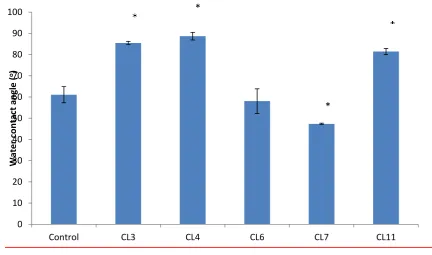
4.3 Advancing water contact angle of modified glass surfaces. Water contact angle was measured
to determine changes in surface energy between the modifications *p<0.05
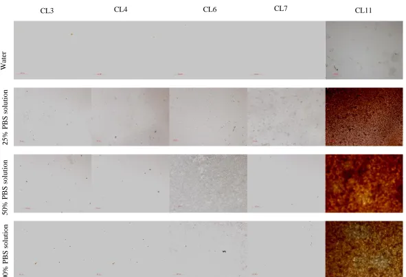
4.44Mineral deposition study, Images show surfaces exposed to differing concentrations of PBS for 7 days, then stained using von Kossa’s stain for mineralisation, positive
staining (brown) shown on CL11.
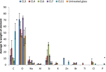
4.5 X-ray analysis of elemental composition of Silane treated glass in 25% PBS. Silane modified
glasses were exposed to PBS for 7 days and then analysed using Xray analysis.. *p<0.05.
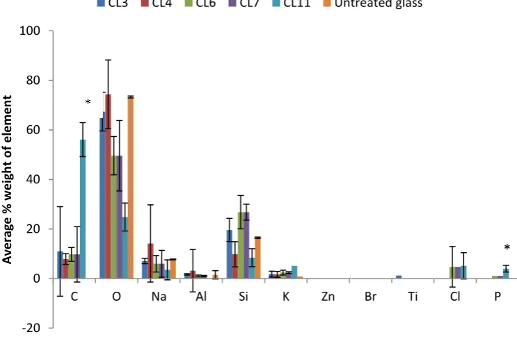
4.6 X-ray analysis of elemental composition of Silane treated glass in 50% PBS. Silane modified
Page xviii 4.7 X-ray analysis of elemental composition of Silane treated glass in 100% PBS. Silane modified glasses were exposed to PBS for 7 days and then analysed using Xray analysis. *p<0.05.
4.8 : Concentration of phosphorous on silane modified surfaces. Surfaces were exposed to
varying concentrations of PBS for 7 days. *=p<0.05. C is an untreated glass control.
.
4.9 Mesenchymal stem cells on modified glass after 7 days
4.10 SEM images of human mesenchymal stem cells cultured on the modified glass for 7 days
4.11 SEM images of human mesenchymal stem cells cultured on the modified glass for 14 days SEM images of human mesenchymal stem cells cultured on the modified glass for 7 days
4.12 SEM images of human mesenchymal stem cells cultured on the modified glass for 28 days
4.14 Expression of osteopontin by human mesenchymal stem cells on modified glass
4.15 Expression of collagen I by human mesenchymal stem cells on modified glass
4.16 Expression of CBFAI by human mesenchymal stem cells on modified glass
4.17 Expression of osteonectin by human mesenchymal stem cells on modified glass
4.18 Expression of osteocalcin by human mesenchymal stem cells on modified glass
419 Expression of sclerostin by human mesenchymal stem cells on modified glass
4.20 Immunostaining of MSCs cultured on modified glass at 7 days. MSC were cultured on silane modified glass for 7 days and stained with Stro-1, DAPI and Oregeon green. Blue staining shows nuclei, green staining shows actin filaments and red staining shows presence of stro-1 (a)untreated control, (b) CL3 (c) CL4, (d) CL6, (e) CL7 and (f) CL114.21
Page xix on silane modified glass for 7 days and stained with collagen I, DAPI and Oregeon green. Blue staining shows nuclei, green staining shows actin filaments and red staining shows presence of collagen I (a)untreated control, (b) CL3 (c) CL4, (d) CL6, (e) CL7 and (f)
4.22 Immunostaining of MSCs cultured on modified glass at 7 days. MSC were cultured on silane modified glass for 7 days and stained with osteocalcin, DAPI and Oregeon green. Blue staining shows nuclei, green staining shows actin filaments and red staining shows presence of osteocalcin (a)untreated control, (b) CL3 (c) CL4, (d) CL6, (e) CL7 and (f) CL11
4.23 Osteoblast-like cells cultured on silane modified glass for 7 days. Osteoblast like cells were cultured on the silane modified glass (and an untreated control) for 7 days, then stained with Von Kossa’s stain for mineralisation (a) untreated glass control, (b) CL3, (c) CL4, (d) CL6, (e) CL7 and (f) CL114.24 , Osteoblast-like cells cultured on silane modified glass for 14 days. Osteoblast like cells were cultured on the silane modified glass (and an untreated control) for 14 days, then stained with Von Kossa’s stain for mineralisation (a) untreated glass
control, (b) CL3, (c) CL4, (d) CL6, (e) CL7 and (f) CL114.25 25 Osteoblast-like cells
cultured on silane modified glass for 28 days. Osteoblast like cells were cultured on the silane modified glass (and an untreated control) for 28 days, then stained with Von Kossa’s stain for mineralisation (a) untreated glass control, (b) CL3, (c) CL4, (d) CL6, (e) CL7 and (f) CL11
4.26 Quantity of nodules formed on the modified surfaces. The nodules were counted using a light microscope. (N=16) Seris 1,2 and 3 correspond to 7, 14 and 28 days, results show avage and error bars show standards deviation from the mean
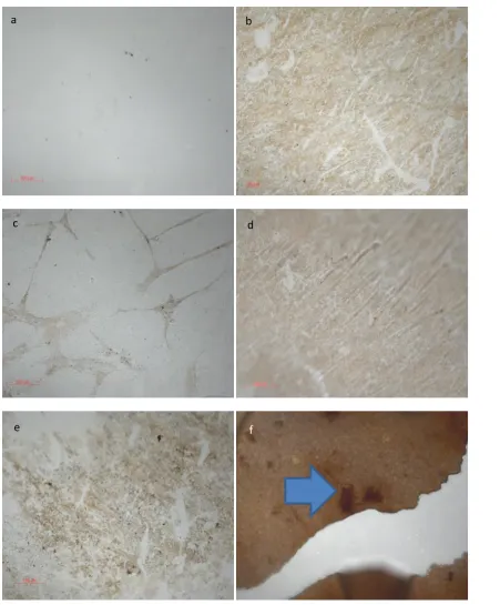
Page xx 4.28 SEM micrographs of Osteoblast-like cells cultured on silane modified glass after 7 days incubation. Osteoblast –like cells were isolated from human trabecular bone and seeded onto the silane modified surfaces. (a) untreated glass, (b) CL3, (c) CL4, (d) CL6 , (e) CL7 and (f) CL11. White arrows indicate nodules, green arrow indicates production of ECM on CL11 and red arrow shows very rounded cells on CL6 modification
4.29 SEM micrographs of Osteoblast-like cells cultured on silane modified glass after 14 days incubation. Osteoblast –like cells were isolated from human trabecular bone and seeded onto the silane modified surfaces. (a) untreated glass, (b) CL3, (c) CL4, (d) CL6 , (e) CL7 and (f) CL11. White arrows indicate nodules, green arrow indicates production of ECM on CL11 and
red arrow shows very rounded cells on CL6 modification 4.30 , SEM micrographs of
Osteoblast-like cells cultured on silane modified glass after 28days incubation. Osteoblast – like cells were isolated from human trabecular bone and seeded onto the silane modified surfaces. (a) untreated glass, (b) CL3, (c) CL4, (d) CL6 , (e) CL7 and (f) CL11. White arrows indicate nodules, green arrow indicates production of ECM on CL11 and red arrow shows very rounded cells on CL6 modification
4.31 SEM micrographs of Osteoblast-like cells cultured on silane modified glass after 7 days incubation. Osteoblast –like cells were isolated from human trabecular bone and seeded onto the silane modified surfaces Image taken from surface of nodule formed at 7 days incubation on CL3. White arrows highlight the fiberous nature of the matrix, and green arrows show areas of smooth mineralisation
Page xxi 4.33 Expression of osteopontin in human osteoblast like cells after 7, 14 and 28 day incubation with silane modified glass. Osteoblast like cells were isolated from human trabecular bone and processed for rtPCR. Expression of osteopontin was measured and normalised to expression of -Actin and unmodified scaffold. Data shown is average expression and standard deviation from mean. *=p<0.10, **=p<0.05, ***=p=<0.01
4.34 Expression of osteocalcin in human osteoblast like cells after 7, 14 and 28 day incubation with silane modified glass. Osteoblast like cells were isolated from human trabecular bone and processed for rtPCR. Expression of osteopontin was measured and normalised to expression of -Actin and unmodified scaffold. Data shown is average expression and standard deviation from mean. *=p<0.10, **=p<0.05, ***=p=<0.01
4.35 Expression of osteonectin in human osteoblast like cells after 7, 14 and 28 day incubation with silane modified glass. Osteoblast like cells were isolated from human trabecular bone and processed for rtPCR. Expression of osteopontin was measured and normalised to expression of -Actin and unmodified scaffold. Data shown is average expression and standard deviation from mean. *=p<0.10, **=p<0.05, ***=p=<0.01
4.36 Expression of collagen I in human osteoblast like cells after 7, 14 and 28 day incubation with silane modified glass. Osteoblast like cells were isolated from human trabecular bone and processed for rtPCR. Expression of osteopontin was measured and normalised to expression of -Actin and unmodified scaffold. Data shown is average expression and standard deviation from mean. *=p<0.10, **=p<0.05, ***=p=<0.01
4.37 Expression of CBFA1 in human osteoblast like cells after 7, 14 and 28 day incubation with
Page xxii 4.38 Expression of sclerostin in human osteoblast like cells after 7, 14 and 28 day incubation with silane modified glass. Osteoblast like cells were isolated from human trabecular bone and processed for rtPCR. Expression of osteopontin was measured and normalised to expression of -Actin and unmodified scaffold. Data shown is average expression and standard deviation from mean. *=p<0.10, **=p<0.05, ***=p=<0.01
5.1 Maximum feature height of silane modified surfaces. Measured using AFM. 5 areas were measured on each sample (n=3) Error bars indicate the standard deviation and * indicates statistical significance (p<0.05)
5.2 AFM micrograph of untreated PLGA film. 12mm diameter glass coverslips were cleaned as
stated in protocol and spin coated with PLGA. AFM images taken from 5 areas per sample, representative image shown
5.3 AFM micrograph of CL3 treated PLGA film. 12mm diameter glass coverslips were cleaned
as stated in protocol and spin coated with PLGA, then modified with CL3. AFM images taken from 5 areas per sample, representative image shown.
5.4 AFM micrograph of CL4 treated PLGA film. 12mm diameter glass coverslips were cleaned
as stated in protocol and spin coated with PLGA, then modified with CL4. AFM images taken from 5 areas per sample, representative image shown.
5.5 AFM micrograph of CL6 treated PLGA film. 12mm diameter glass coverslips were cleaned
as stated in protocol and spin coated with PLGA, then modified with CL6. AFM images taken from 5 areas per sample, representative image shown.
5.6 AFM micrograph of CL7 treated PLGA film. 12mm diameter glass coverslips were cleaned
Page xxiii
5.7 AFM micrograph of CL11 treated PLGA film. 12mm diameter glass coverslips were cleaned
as stated in protocol and spin coated with PLGA, then modified with CL11. AFM images taken from 5 areas per sample, representative image shown
5.8 . Ninhydrin assay of amine concentration on the modified PLGA surfaces. Concentration of
amine on surfaces was measured by ninhydrin assay. Results show averages and error bars show standard deviation from mean *=p<0.05,
5.9 Dynamic water contact angle The average advancing angle across the mid point of the surface
was measured (n=6) Stars indicate degree of difference between untreated control and CL3 and 4 and CL6 and 7 and CL11. Error bars indicate standard deviation. *=p<0.10, **=p<0.05, ***=p=<0.01
5.10 Correlation between dynamic water contact angle and number of carbon atoms in
hydrocarbon chain of silane molecule. Results were plotted as a correlation and R2 value showed a significant correlation
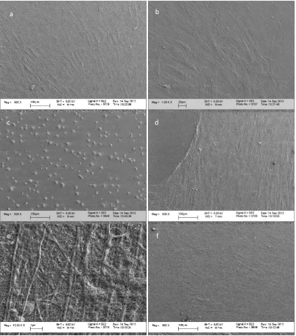
5.11 SEM of modified PLGA films. Films were modified with (a) Untreated PLGA(b),CL3 (c),CL4 (d),CL6 (e) CL7and (f) CL11. White arrows indicate macroscopic topographical structures on CL11
5.12 hMSC on modified PLGA films. Films were modified with the following
modifiections;(a)untreated PLGA (b) CL3 (c) CL4, (d) CL6, (e) CL7, and (f) CL11. After 7 days incubation with hMSC they were fixed and stained with Von Kossa stain for
mineralization. (f) White arrows show positive mineralization staining on CL11 modification.
5.13 hMSC on modified PLGA films. Films were modified with the following
Page xxiv days incubation with hMSC they were fixed and stained with Von Kossa stain for mineralization. (f) Shows positive mineralization staining on CL11 modification
5.14 hMSC on modified PLGA films. Films were modified with the following
modifiections;(a)untreated PLGA (b) CL3 (c) CL4, (d) CL6, (e) CL7, and (f) CL11. After 28 days incubation with hMSC they were fixed and stained with Von Kossa stain for mineralization. (f) Shows positive mineralization staining on CL11 modification
5.15 Mean concentration of amine groups on treated PLGA spheres. The concentration of amine
groups was measured by nynhydrin assay.Error bars show standard deviation from the mean
(n=4). Star indicates statistically significant reduction in coverage when compared to CL3, CL6 and CL11 (p=<0.05)
5.16 hMSC on modified PLGA scaffolds. Scaffolds were modified with with (a) CL3 (b) CL4,
(c) CL6, (d) CL7, (e) CL11 and (f) untreated PLGA and cultured for 28 days. After
incubation the samples were processed, sectioned and stained with H and E.5.17 hMSC on
modified PLGA scaffolds. Scaffolds were modified with with (a) CL3 (b) CL4, (c) CL6, (d) CL7, (e) CL11 and (f) untreated PLGA and cultured for 28 days. After incubation the samples were processed, sectioned and stained with Von Kossa’s stain for mineralisation.
5.18 hMSC on modified PLGA scaffolds. Scaffolds were modified with with (a) CL3 (b) CL4,
(c) CL6, (d) CL7, (e) CL11 and (f) untreated PLGA and cultured for 28 days. After incubation the samples were processed, sectioned and stained with Alizarin red for mineralisation.
5.19 hMSC on modified PLGA scaffolds. Scaffolds were modified with with (a) CL3 (b) CL4,
Page xxv cultured for 28 days. After incubation the samples were processed, sectioned and stained with. Van Giesons stain for collagen
5.21 LDH assay for cell number. hMSC were seeded into silane modified scaffolds and cultured
for 7, 14 and 28 days. Error bars indicate standard deviation from mean. *shows a statically significant difference (p<0.05), than the same modification at 7 days.
List of tables
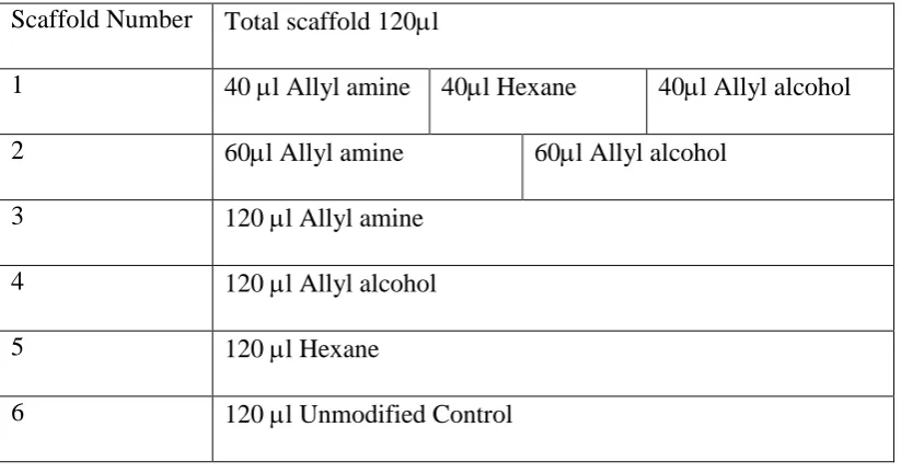
2.1 Diagram showing quantities and layer format of modified spheres incorporated into scaffold
2.2 Primer bases for the corresponding gene of interest, and temperature at which reaction takes place
2.3 Index or silanes used for modifications
2.4 Matrix of experiments conducted using varying concentrations of PBS
2.5 Dilutions of PBS
2.6 Concentrations of primary antibodies
2.7 Table of primary antibodies with their corresponding secondary antibodies
3.1 Chemical modification and most abundant chemical group deposited from modification
3.2 XPS Summary table (n=6) % Weight of element on the Plasma treated surfaces ± standard
deviation of repeats
3.3 Summary of Histology results after 7 days culture.
3.4 Summary of Histology results after 14 days culture
Page xxvi 3.6 Summary of results for the dual and triple modified scaffolds.
4.1 PBS interactions with modified glass. + indicated positive Von Kossa staining for
mineralisation
4.2 Probability of phosphorous occurring on the surfaces. 0 = no probability and 1= high probability.
5.1 Summary of histological staing from 3D scaffolds with mesenchymal stem cells incubated for
Page xxvii
Abstract
Non-union fractures are defined as fractures that do not heal after 6 months of conventional treatment. They usually require multiple surgical treatments, autologous bone grafts or treatments with growth factors or Bone morphogenetic proteins (BMPs). There is a clinical need for a material which can be used to replace autologous bone transplantation in the treatment non-union fractures that negates the problems associated with autologous grafts.
This thesis aims to consider and develop a coating that can be used on a readily available polymer biomaterial to induce a response from mesenchymal stem cells, which are found in abundance at fracture sites, and facilitate repair by their differentiation into osteogenic cells. The use of a synthetic chemical coating rather than a growth factor or peptide aims to cause similar effects at a greatly reduced cost
Plasma application techniques were used initially to screen potential terminal groups on a 3D system. Amine groups were found to be osteogenic (which was confirmed by positive Von Kossa and Alizarin red staining), and hydroxyl groups were found to be chondrocytic (which was confirmed by positive Van Geison and Alcian blue staining). The osteogenic effect of the amine group was investigated further, but in the form of silane SAMs, which were more easily definable. The presentation of the terminal group was investigated using varying carbon chain length, to see if this had an effect on osteogenicity) This was explored using both MSC and primary osteoblast-like cell models on glass initially, then on PLGA films and finally a 3D PLGA system.
Page 1
Chapter 1:Introduction, Literature Review and
Hypothesis
1.1 The Principles of Regenerative Medicine
The primary purpose of regenerative medicine is to provide strategies to replace tissue
when injury, disease or congenital defect causes it to be missing1. This is becoming more and more important. Therapies that enable people to retain their healthy bodies beyond what is
experienced today, in this changing economic climate with an aging population, will become
more relevant.
The natural response to injury, depending on the location, is to fill the space created
by degraded tissue with scar/fibrous tissue. This often has insufficient mechanical and
functional properties to provide the full functionality of the tissue lost and can lead to severe
complications. The core principle of regenerative medicine is to guide the healing process
using a range of signals to improve the quality of the repair, achieving more natural tissue
faster, hence providing improved functionality more quickly. This principle in its broadest
sense can be applied to any aspect of regenerative medicine, but for the purposes of this
thesis, the issues surrounding skeletal regeneration will be the main focus.
1.2 Bone Fracture
Most uncomplicated bone fractures will heal after 3-4 months of conventional
treatment. There is a little variation depending on the site of the fracture, but as a general rule,
this is considered to be correct. Clinicians will use X-rays to determine the normal
physiological anatomy of the bone has been restored. There are also a few physiological tests
Page 2 of pain with movement, and ability to bear weight. When the normal pathway of treatment is
not effective, the fracture is defined as being non-union2.
1.3 Non Union Bone Fracture
A non-union bone fracture is defined as a bone injury that fails to heal after six
months - when conventional treatments have been applied, or a fracture that has shown no
progression of healing for 3 months2. There is some debate about this figure as some delayed unions can occur after the 6 month period has passed, particularly if there have been
complications such as infection in the site, but as a general rule, the 6 month period is the
guideline most clinicians use2. The repercussions of non-union bone fractures for the patient can be impaired function and skeletal deformity. It is expensive to treat, and often causes the
patient to have numerous surgical procedures3. The root cause of why some patients experience this failure to heal is not well documented, however there are some indications in
the literature that the initial cellular response is considerably different in patients suffering
from non-union fractures4.
Webber defined two types of non-union fracture, depending on the viability of the
fragments of bone present. The first classification is called the hyper-vascular or
hypertrophic non-union. In this presentation of the non-union fracture, the bone ends are still
biologically active and have a functioning blood supply. A light callus forms because there is
slight movement in the joint around the fracture site, which is not detectable until the patient
is in surgery, but the callus prevents the fracture ends from joining. It is a well-established
fact that the bone ends need to be totally immobilised to fully join, and even slight motion
can be responsible for non-union fracture. Hyper-vascular non-union fractures have been
defined as taking three different presentations. The first presentation is the “elephant foot”
Page 3 callus that broadens at the fracture site. The reason for this presentation varies, but can be
linked to poor fixation, the join being too mobile, or due to premature loading of weight,
which can lead to peudoarthrosis. The second presentation contains less callus and is named,
“horses foot” which is less hypertrophic. This presentation is more common if the fixation of
the bone has been slightly unstable and is more likely to spontaneously join, as the callus
forms and stabilises the fracture. The third presentation is oligotrophic, and contains no
callus and is referred to as a lax non-union fracture2.
The second classification is avascular non-union bone fracture. In this class the bone
fractures are avascular or atrophic and not able to form callus. These are the more
problematic fractures as they show no changes over long periods of time, and require
sustained surgical intervention as immobilisation will not allow the bone ends to heal as they
are no longer vital. Avascular non-union is defined by one of four presentations. The torsion
wedge non-union is defined as a fragment of non-viable bone which has fused onto one of the
viable ends. The comminuted union occurs if the fragments are necrotic. Defect
non-unions occur if a piece of the bone has been lost, during an accident, or because of infection.
In these cases the ends can still be viable but the distance between them is too large to bridge,
and because of this the ends become atrophic. Lastly there are the atrophic non-unions,
which usually start out as one of the other classifications and are the end point of the
non-union2.
If left untreated the medullary canals become blocked, and the bone ends become
joined by fibrous tissue. Pseudoarthrosis can form, which takes either a stiff or lax form.
Page 4 of autologous tissue. One possible solution is the application of a material to support stem
cell growth and differentiation. Increasing and enhancing the healing process between the
non-union ends of the bone, with an aim to regenerate functional and calcified bone in the
void rather than fibrous tissue that can lead to pseudoarthrosis.
1.4 Normal Bone Healing Pathway
The sequence of events after a bone fracture has occurred starts with the formation of
a haematoma. Injury incurred to the vascular system causes the clotting cascade to be
stimulated and haematoma formation. The haematoma contains large volumes of platelets
and releases cellular signals. Inflammation is initiated with an increase in localised blood
flow and permeability of the blood vessels. There is a migration of leukocytes to the injury
site stimulates more cytokines to be released, recruiting mesenchymal stem cells (MSC) to
the site of injury. MSC proliferate and differentiate into osteoblast-like cells and there is
increased angiogenisis. Ossification then occurs, where the osteoblasts start to lay down a
collagen network, which then ossifies to form a callus capable of bridging the gap between
bone ends. At this point the callus is named lamellar bone. The last phase is remodelling
which is orchestrated by osteoclasts and results in the woven bone formation, which has
better mechanical properties than lamellar bone7.
There are four major populations of cells responsible for the regeneration of bone:
Osteoblasts, which have a regenerative role, and originate from MSC and are the main
Page 5
Osteoclasts, which are the enzyme producing cells that can dissolve collagens and are
the key to bone remodelling, originate from the haemopoteitic stem cell fraction of
bone marrow.
Osteocytes, which are differentiated osteoblasts, and have a less productive and more
regulatory role.
Bone lining cells, which are osteocytes which are not embedded in the bone matrix,
line the bone surface, remaining inactive until they are stimulated to change8.
During fracture healing the role of MSC is vitally important. They are the essential
player in the bone regeneration process, and it has been shown that the bone morphogenetic
proteins (BMPs) play key roles in mesenchymal stem cell recruitment in vivo9. There is also some evidence to suggest that stromal cell derived factor -1 (SDF-1) plays a role in regulating
the recruitment of MSC to the site where they are required9.
1.5 The Formation of a Cartilaginous Callus
The formation of a cartilaginous callus is the result of initial stem cell differentiation,
which later will be mineralised and remodelled. This cartilaginous callus is the blueprint for
the formation of bone, and provides many of the raw materials required. The ossification of
the callus occurs at the bone ends before it bridges into the central portion of the callus. This
causes the initial stabilisation phase.
On a molecular level, it is at this point collagen I and II are produced in abundance,
and the transforming growth factor beta (TGF- peptides are involved in endochondral
ossification. The BMPs are also involved in the ossification process10. The vascularisation of the site is a necessity if the callus is to lead to full bone repair. There is a fine balance
Page 6 to make way for it. Vascular endothelial growth factor (VEGF) plays a principle role in the
angiogenesis of the fracture site.
After angiogenesis has occurred the cartilaginous callus should be resorbed and
replaced by a bony callus which has greater mechanical properties. The number of cells in
the bone fracture site increases as they are switched into a proliferative state, allowing more
extracellular matrix to be produced. The Wnt family of molecules is likely to be key
facilitators in this in the differentiation of MSCs to osteoblasts, which is required for this step
in fracture healing to occur. Chondrocytes from the callus proliferate quickly during this
phase of the healing process and can become hypertrophic which can lead to the extracellular
matrix becoming calcified. When this occurs there is a cascade of inflammatory cytokines
including macrophage-colony stimulating factor (M-CSF), receptor activator of nulear factor
kappa B ligand (RANKL) osteoprotegrin (OPG) and tissue necrosis factor alpha (TNFa).
This cascade allows the recruitment of more osteoblasts and osteoclasts which promotes
chondrocyte apoptosis. Calcium accumulates in the mitochondria of the chondrocytes in this
hypoxic environment. Calcium is transported though the cytoplasm and is deposited in the
extracellular matrix (ECM), where they can precipitate with phosphate and start the
mineralisation process. These initial deposits nucleate and form apatite crystals, which are
carried to the nucleation point in microvesicles11, forming the hard callus. As the calcified cartilage is mineralised it becomes woven bone9. The growth factors that are responsible for this phase of osteoblastic activity have been studied extensively and it has been determined
that there is a balance required of several growth factors including transforming growth
factors (TGF-B1, TGF-B2 and TGF-B), vitamin D and fibroblast growth factor (FGF-2)
which are key players in maintaining osteoblast function and establishing a mineralisation
Page 7 The next phase is the remodelling of the woven bone so that it can become lamellar
bone with a medullary cavity. Again, the inflammatory cytokines interleukin 1(IL-1) and
tumour necrosis factor alpha (TNF alpha) have a role to play in the second reabsorption
phase. The BMPs also have roles to play in this phase, especially bone morphogenetic
protein 2 (BMP-2). During this phase it is the role of osteoclasts to reabsorb the woven bone,
and the job of the osteoblasts to extrude correctly structured lamellar bone. This is a process
which can take years to be fully achieved, and requires specific environmental conditions,
creating an inductive electrical polarity, by the correct amount of pressure being loaded onto
the micro-crystalline environment.
1.6 The in vivo Osteogenic Differentiation Pathway of Mesenchymal Stem Cells
Bone formation is a complex morphological process that results in complete
differentiation of MSCs, at a temporally correct point within a constantly fluxing system, and
at the correct location.
Multiple local and systemic factors play a role in this differentiation. The local
factors that instigate and maintain osteogenic differentiation of MSCs include transforming
growth factor beta (TGF-B), core binding factor alpha-1 (CBFA-1), alkaline phosphtase
(ALP), collagen I, osteopontin (OP), osteonectin (ON), bone sialoprotein (BSP), apoptosis
mediating surface antigen (Fas), the interleukins (IL), and the apoptosis regulating
Bd-2-associated X protein (BAX). These local factors however do not work in isolation and there
are also some systemic factors that stimulate the osteogenic response, including parathyroid
hormone, vitamin D, leptin, calcitonin, somatotropin, thyroxine, estrogens, androgens and
Page 8 help to support the pathway of the MSC, to pre-osteoblast, to mature osteoblast and all the
mineralisation phases, and ultimately to apoptosis or maturation into osteocyte morphology13.
To highlight just a few of these factors in a little more detail, the role of CBFA-1 is
vital to the osteogenic process, and is considered a key marker of osteogenesis. It is a
member of the runt-related transcription factor (RUNX) family of transcription factors, and
has demonstrated an important regulatory role where it stimulates the up-regulation of
osteoblast genes such as osteocalcin. It could be described as the corner pin of the osteogenic
response and this is one reason why this marker is used so frequently as a marker of
osteogenesis14,15. Caution should be taken however when using CBFA-1 as a marker of the osteogenic differentiation of MSCs, as it is a transcription factor, and will only be present in
the early phases of differentiation, for short periods of time, so it is not a marker that could be
used alone, but would add weight to a panel of markers for osteogenesis.
Osteonectin is expressed in pre-osserous cells, as well as osteoblasts and is one of the
first indicators of osteogenic differentiation. However is is not specific to osteogenic
differentiation as it can also be expressed by cells undergoing a chondrogenic lineage
differentiation16. Osteopontin is expressed during the mineralisation process, and is only present when mineralisation is occurring. It has been shown to be present in cells found
adjacent to mineralised matrix16. Osteocalcin is a marker of bone metabolism, and has been used extensively as a marker of new bone formation17. It could be described as a bone-specific protein which consists of a sequence 49 amino acids18. Osteocalcin is only secreted by osteoblasts that have been in contact with an established mineralised matrix and so is a
very specific marker of functioning cells.
The TGF super-family contains all the BMPs and are involved in many
Page 9 bone regeneration, as is BMP 710. TGF-beta itself has been shown to increase bone formation in vitro, by allowing osteoblasts to expand in culture more readily, but seems to retard the mineralisation effect12.
1.7 Current Therapy for Bone Loss in Non Union Fracture
Autologous bone grafts are the gold standard for the treatment of non- union bone
fractures. There are many reasons why autologous bone grafts are the treatment of choice.
The bone harvested can be classified as osteoinductive, as it contains viable MSCs and
osteoblasts in addition to the molecules that are necessary to induce undifferentiated cells
along an osteogenic lineage, such as BMPs and members of the TGF super family. It can
also be classified as osteoconductive, because its structure (particularly if it is cancellous
bone), will allow the in-growth of cells from the adjacent bone ends of the fracture site. All
the factors required to achieve a repair are present, because the bone taken from a donor site
in the patient’s body is ideally suited for the purpose of filling a non-union fracture void19 .
The type of bone harvested does influence the success and the mechanical stability of the
repair. Cancellous bone, as described above has lots of properties that influence and bring
about a good repair, but initially it has no mechanical strength, and it takes approximately 12
months for the repair to be as mechanically sound as normal bone. Conversely, cortical bone
has better mechanical properties but because of its dense structure, is less effective at
delivering the appropriate factors to the site19. But, removing bone from another area of the patient’s body to use in the fracture site is not always possible, depending on the size of the
Page 10 Donor site morbidity is a serious problem, and the use of the fibula as a harvesting
site can lead to pain, muscle weakness, nerve damage, infection, stress fractures and joint
instability. It is thought that up to 57.7% of patients experience some of these
complications20. Short term complications such as muscle weakness, do improve over a short period of time, but pain can last in excess of 12 months in some patients20. The quality of the autologous bone graft also reduces with the age of the patient21.
Bone marrow aspirates are used to treat non-union fractures in some instances, where
relatively large quantities of bone marrow are used and where stem cells are added back into
the site. There are several problems associated with this technique, one being that there is no
means of keeping the cells in the intended location if no scaffold is used. The quantity of
bone marrow required to do this procedure could cause other complications20.
Allografts are the next option for treatment after the other possibilities have been
explored. Allografts use de-cellularized bone from human cadavers or live donors. They are
less effective than autografts as the processing used to make them safe to use in other
patients, strip them of many of the factors that make the graft osteoinductive, and mean that
only their osteoconductive properties remain, loosing many of the osteogenic properties20. Complications from using donor tissue like this include transmission of viruses, including
very rarely human immunodeficiency virus (HIV). Bacterial infection is also more likely,
with some reports suggesting that these rates are as high as 12.8%, but this is variable in the
literature20,21.
The use of bone morphogenetic proteins (BMPs) as a therapy greatly increases the
healing potential of non-union fractures22, as an overview of the studies conducted into the use of BMPs states that success rate in patients who were treated for pseudoarthrosis was
Page 11 seen to be a good substitute21,22. Initially it was thought that BMP2 was completely safe for human use, as initial studies undertaken in 2002 showed no complications arising from its use
for bone regeneration. This, however, was not the case and initial studies have been
discredited. Later studies, when rhBMP2 was in general use in several countries, found that
there were severe complications, including overgrowth of bone, osteoclast stimulation and
activity leading to graft failure, local wound problems, including inflammation, neurological
complications and carcinogenic properties23. Treatment using BMP 7 seems to be showing some promise to date24.
There are incidences where a synthetic bone regeneration system, which has
osteoinductive, osteoconductive and osteogenic potential and is close to the gold standard of
autologous bone, would be clinically-relevant and aid the recovery of patients with severe
and often life-threatening injury. The direction of the work undertaken in this thesis is
influenced heavily by this aim.
1.8 Synthetic Bone Grafts
Of the synthetic bone grafts, the ceramic-based materials are the most commonly
used. Hydroxyapatite and -tricalcium phosphate are the most common of this subset. There
are a few advantages to these materials over allogeneic bone, as there is no risk of virus
transmittance, and they have a very long shelf life. They are osteoconductive but not
osteoinductive when used in their unmodified states21. To fully integrate they are reliant on bone in-growth, and need to be stable under physiological conditions to last long enough for
this to occur. One disadvantage of hydroxyapatite is that there is no reabsorption by
osteoclasts, unlike allografts, which are eventually reabsorbed. Conversely, the material will
Page 12 1.9 The Ideal Bone Biomaterial
The ideal bone biomaterial would have all of the properties of an autologous graft. It
would have the capability to be osteoconductive, osteoinductive and osteogenic. It would be
osteoconductive to allow full integration with the host skeletal tissue, it would be
osteoinductive to the cells that migrate into the material from the host, but ideally it would
also be osteogenic as it could be used as a carrier or delivery system for the patient’s own
therapeutic MSC. The material would have mechanical properties similar to the tissue it
intends to replace and, ideally if used in conjunction with cells, be degradable at the same rate
as cells can mineralise the scaffold. If this was incorporated into an easy to use injectable
system that could bridge gaps of any shape or size it would be both clinically useful, and
remove the requirement for autologous bone harvesting, thus improving the health of the
patient.
During this work, we have taken an injectable polymer system which already has
osteoconductive properties, and mechanical strength similar to trabecular bone, and changed
its surface chemistry to boost its osteoinductive properties, while testing its osteogenic
potential using an in vitro MSC model.
1.10 Mesenchymal Stem Cells (MSCs)
It has already been stated that MSCs play a crucial role in the normal healing pathway
of bone fracture injuries. Undifferentiated stem cells migrate to the area where they are
required and are stimulated by BMPs and regulatory cytokines to proliferate and differentiate
Page 13 current bone regeneration research has concentrated on using BMPs in their various forms to
stimulate this natural healing response26. Mimicking and enhancing this response should lead to a successful therapy. This is one of the reasons why adult MSCs are ideal candidates for
autologous bone regeneration.
There are multiple sources of MSCs within the body27. Most tissues contain their own source of cells, but their potency and their niche varies between tissues. It is the current
opinion that a stem cell isolated from adipose tissue will not be capable of achieving the same
fate as a stem cell derived from blood. While there may be a small degree of overlap, there is
a fundamental difference in their differentiation capability. Bone marrow derived MSCs are
considered to be more potent than stem cells derived from other adult tissues25. There are two populations of stem cells found in the bone marrow, these are MSCs and hematopoietic
stem cells. Hematopoietic stem cells have a very specific niche where they produce blood
cells and osteoclasts. Hematopoietic stem cells are unlikely to be used as a cell for bone
regeneration which is regulated by the osteoblastic lineage. However, bone marrow derived
MSCs are likely to be very useful for this task.
It is currently considered that bone marrow derived mesenchymal stem cells
(BM-MSCs) are pluripotent, rather than multipotent28 as they can, and have been stimulated to differentiate into cells that derive from each of the germ layersfor example they can be
pushed down osteogenic and chondrogenic 29 pathways from the mesoderm, neurons which originate from the ectoderm 30, and pancreatic cells and hepatocytes from the endoderm31,28.
BM-MSCs are ideal for any osteogenic lineage induction as this cell type plays a role
Page 14 increase cell number until enough of the patients own cells are available to perform a
regeneration procedure. Another advantage is the isolation techniques are relatively simple,
and exploit the cells inherent ability to adhere to plastic when cultured. The bone marrow
aspirate, usually taken from the iliac crest, is first subjected to sorting of nucleated cells from
other material via a density gradient. Then the nucleated cells are cultured for 24 hours in an
appropriate media, and all non-adherent material is removed34.
The lack of standardization in the initial isolation, characterisation of the cell
population, and culture methodology can be problematic. There is variation between
techniques used to isolate and culture MSCs, and these subtle variations could be responsible
for some of the conflicting results seen in some studies. It is for this reason it is often
unreliable to compare results obtained from different research groups, and it could explain
some of the discrepancies seen35. Therefore there is a need for standardization of isolation protocols, characterization of resultant cell populations and expansion techniques.
There is patient variability in these cells and often the age and general health of the
patient can affect how these cells proliferate in vitro. Any work undertaken with primary MSCs should consider donor variation36. There was considerable donor variation demonstrated by Zhukareva et al36, when MSC response to pro-inflammatory cytokines was measured using a panel of markers. This study exemplifies how the patients’ cells will
behave differently when exposed to exogenous stimuli. This however, does not detract from
the positive aspects of adult human MSCs, but must be considered when any research
involving these cells is undertaken in respect of the number of repeats necessary to validate a
given response36.
One of the most remarkable advantages of using MSCs relates to their immunological
Page 15 immunologically privileged because they express major histocompatibility complex I (MHC
I) but not major histocompatibility complex II (MHC II). They do not express the cluster of
differentiation antigens (CD antigens) CD40, CD80 or CD86 which stimulate an immune
response. These cells will evade the immune system of the host, and there is some evidence
to suggest that the MSCs can suppress T cell proliferation37.
1.11 The Identification and Profile of Mesenchymal Stem Cells
The definition of the BM-MSC has been problematic. The answer to that issue is not
simple, because the defining feature of a stem cell is that it has the potential to change into
any number of other cells, all of which will present markers the BM-MSC may also present.
A panel of positive and negative markers is therefore the way they are defined, and should be
defined periodically throughout the lifespan of the culture. This brings together a profile of
the cell that a potential BM-MSC has to meet. Positive markers of BM-MSCs include CD73,
CD90, CD105. BM-MSCs should also be CD34, CD45, CD14 or CD11b, CD79 or CD19
and HLA-DR negative. The minimum number of cells expressing CD73, CD105 and CD90
in a population should be 95%. The maximum number of cells expressing the negative
markers should be 2%38. If this profile is used universally by researches it may go some way towards creating a standardized profile by which MSCs are defined and creating a cohesive
methodology.
There is also a physical requirement that needs to be met, when defining BM-MSCs,
which is their ability to adhere to plastic in culture. If they do not adhere to plastic they are
not MSCs. The cells also need to have at least a multipotent differential potential. They must
be capable of differentiation into osteoblasts, chondrocytes and adipocytes as a minimum
requirement, under the appropriate stimuli. Histological stains can be used as evidence of
Page 16 mineralization, chondrocytes using Alcian blue for glycos-amino-glycan (GAG) and
adipocytes can be stained with Oil red O for lipids38.
Another problem that researchers face when using BM-MSCs is that of senescence.
Embryonic stem cells (ESC) go through many passages, and remain phenotypically correct,
where BM-MSCs will only passage a relatively small number of times before they lose their
stem markers and become senescent. This creates problems when it is necessary to achieve
the large cell numbers required for cell therapies39. Senescence is thought to occur due to shortening of telomere length during cell division, and as this is also a phenomenon observed
during the natural ageing process, it also suggests that stem cells from older patients will be
more prone to senescence40. It is necessary to use MSCs before they get to the point of senescence. It is important before undertaking any experiment with cultured mesenchymal
stem cells that they are tested to express the panel of stem cell markers mentioned previously,
as senescence halts their expression40. The characterisation of MSC populations will ensure the cells used in any experiment or therapy are a homogeneous population most likely to
behave in a predictable way, being more predisposed to differentiate.
1.12 Differentiation of Mesenchymal Stem Cells
The aim of differentiating MSCs is to create terminally differentiated cells that have
applications for treating disease or injury. The ultimate goal is to be able to put MSCs into the
body, either on a scaffold or on their own. They get their cues from the physical and chemical
properties of the scaffold, either prior to implantation or after. Alternatively, the scaffold can
Page 17 There is evidence to suggest that MSCs have been differentiated into many different
cells and tissues. Adipogenic differentiation of MSCs would potentially be very useful for
producing a filler material for reconstructive surgery 41. Chondrogenic differentiation is leading to the growth of new cartilage that would represent a significant advance for the
treatment of sports injuries 42. Osteogenic differentiation could help surgeons repair non-union bone fractures43 and the production of nervous tissue through neural differentiation would help many people who are paralysed with spinal injuries30. Differentiation of MSCs into pancreatic islet cells may be an avenue to explore for type 1 diabetes mellitus31. The underlying fundamental science of the cell differentiation pathways is not yet fully
understood. It is possible to promote differentiation in vitro using a wide range of stimuli using many different physical factors, exogenous growth factors supplied via culture media,
or the interactions of cells with a surface.
1.13 Cell Delivery Systems for Bone Regeneration
Stem cell therapies undoubtedly have a lot of potential in regenerative medicine.
Seeding MSCs at the area where the regeneration is required to occur, is more problematic
than first anticipated. A quantitative study of the delivery of MSCs into a rat model by two
intravascular routes (the coronary artery and directly into the myocardium) demonstrated this
particularly well. The cells injected were labelled and it was shown that none of the cells
injected into the coronary artery were found in the myocardial tissue, and only 15% of the
cells injected directly into the myocardium were found to have been retained. This example
Page 18 the cells were found in the spleen, liver and lungs of the rat model44. The small retention rate highlights the necessity of a delivery system that will retain the appropriate number of cells in
the designated area of application.
As stated above, a major obstacle in the development of a stem cell-based therapy is
the delivery of the cells to the required location. A delivery system is needed that fulfils the
requirements of being both conducive to MSC proliferation and differentiation but also
degradable at a rate that allows tissue regeneration to occur, and has the correct mechanical
properties to substitute bone whilst regeneration occurs. There are a few studies (outlined
below) that are working towards some of these properties.
Some injectable hydrogels show promise for the stimulation and delivery of bioactive
compounds to a site of injury, but struggle to match up to the mechanical properties required
for bone replacement, particularly if the replacement has to bear weight45. Injectable systems that would bear weight such as foamed injectable hydroxyapatite scaffolds, require exact
timing of the injection to retain their pore structure which is vitally important for the
osteoconductivity of the material, and the application of this in surgery would be
impractical46. Some studies have tried to combine the two techniques, using a hydrogel to encapsulate umbilical cord stem cells prior to incorporation into a calcium phosphate paste47. While this study has showed some positive results, there is still the question of how this
technique could be used in a clinical setting. Putting aside the issues regarding using
umbilical cord stem cells and the risks of viral transmission that come into play when using
donor cells, the encapsulation process requires specialised equipment to achieve the size of
spheres required to maintain the mechanical strength required for bone applications. Several