City, University of London Institutional Repository
Citation
:
Katritsis, D. G., Theodorakakos, A., Pantos, I., Gavaises, M., Karcanias, N. and Efstathopoulos, E. P. (2012). Flow Patterns at Stented Coronary Bifurcations Computational Fluid Dynamics Analysis. Circulation: Cardiovascular Interventions, 5(4), pp. 530-539. doi: 10.1161/CIRCINTERVENTIONS.112.968347This is the accepted version of the paper.
This version of the publication may differ from the final published
version.
Permanent repository link: http://openaccess.city.ac.uk/7294/
Link to published version
:
http://dx.doi.org/10.1161/CIRCINTERVENTIONS.112.968347
Copyright and reuse:
City Research Online aims to make research
outputs of City, University of London available to a wider audience.
Copyright and Moral Rights remain with the author(s) and/or copyright
holders. URLs from City Research Online may be freely distributed and
linked to.
City Research Online: http://openaccess.city.ac.uk/ [email protected]
Flow Patterns at Stented Coronary Bifurcations:
Computational Fluid Dynamics Analysis
Demosthenes G. Katritsis, MD, PhD, FRCP,1Andreas Theodorakakos, PhD,2Ioannis Pantos, MSc,1,3Manolis Gavaises, PhD,4Nicos Karcanias, PhD, DSc,4Efstathios P.
Efstathopoulos, PhD3
Short title:Flow Patterns at Stented Coronary Bifurcations
1
Department of Cardiology, Athens Euroclinic, Athens, Greece,
2
Fluid Research, Athens, Greece,
3
Medical and Radiation Physics, Department of Radiology, University of Athens, Greece,
4
School of Engineering and Mathematical Sciences, The City University, London, UK
Correspondence:
Dr D. Katritsis, Department of Cardiology, Athens Euroclinic,
9 Athanassiadou Str., 115 21 Athens, Greece
Tel 210 6416600, Fax: 210 6416661, E-mail:[email protected]
Word count:5956
Abstract
ObjectivesTo assess hemodynamic parameters known to affect the risk of restenosis and
thrombosis at coronary bifurcations following various single and double stenting techniques.
BackgroundThe ideal bifurcation stenting technique is not established and data on the
hemodynamic characteristics at stented bifurcations are limited.
Methods and ResultsWe employed computational fluid dynamics analysis to assess the
distributions and surface integrals of the time averaged wall shear stress (TAWSS),
oscillatory shear index (OSI) and relative residence time (tr). Single main branch stenting
without side branch balloon angioplasty or stenting provided the most favourable
hemodynamic results (integrated values of TAWSS=4.13∙10-4 N, OSI=7.52∙10-6
m2, tr=5.57∙10 -4
m2/Pa)with bifurcational area subjected to OSI values >0.25, >0.35, and >0.45 calculated as
0.36mm2, 0.04mm2, and 0 mm2, respectively. Extended bifurcation areas subjected to these OSI values were seen after T-stenting: 0.61mm2, 0.18mm2, and 0.02mm2, respectively. Among the considered double stenting techniques, crush stenting (integrated values of
TAWSS=1.18∙10-4 N, OSI=7.75∙10-6
m2, tr=6.16∙10-4m2/Pa) gave the most favourable results
compared to T-stenting (TAWSS=0.78∙10-4 N, OSI=10.40∙10-6
m2, tr=6.87∙10-4m2/Pa) or the
culotte technique (TAWSS=1.30∙10-4 N, OSI=9.87∙10-6
m2, tr=8.78∙10-4m2/Pa).
ConclusionsStenting of the main branch with our without balloon angioplasty of the side
branch offers hemodynamic advantages over double stenting. When double stenting is
considered, the crush technique with the use of a thin strut stent results in improved
hemodynamics compared to culotte or T stenting.
Introduction
Coronary bifurcations remain one of the most challenging lesion subsets, even in the era of
drug eluting stents (DES). Single stent implantation in the main vessel with provisional
stenting to the side branch vessel has been found superior to double stenting1, 2and is considered the default approach in most coronary bifurcation lesions.3However, in true bifurcation lesions, this provisional approach may leave significant residual stenosis of the
side branch vessel after PCI, and in recent randomized study, double stenting reduced target
vessel revascularization without affecting major adverse coronary events compared to
provisional side branch stenting.4Thus, operators may opt for double stenting in the presence of a big side branch. Still, the ideal stenting technique is not established in this respect.
Several methods for deployment of two stents at bifurcations have been proposed, but
their impact on clinical outcomes such as restenosis and, especially, stent thrombosis and
iatrogenic myocardial infarction, still a reason for concern with DES,5is not known. Stenting at the site of bifurcation inevitable affects coronary flow patterns that have been associated
with restenosis rates and stent thrombosis.6Indeed, altered geometry and associated blood flow disturbances induced by stenting can influence restenosis.7, 8Disturbed flow may also facilitate the accumulation of platelets and other blood thrombogenic factors close to the wall.
9, 10
Flow patterns in bifurcations are inherently complex, including vortex formation and
creation of zones of low and oscillating wall shear stress that coincide with early intimal
thickening.11, 12Luminal dimensions and flow patterns are theoretically restored after PCI, but bifurcation stenting is associated with geometric deformation of both the main and side
branch and, most importantly, introduction of stents struts into the coronary artery, with
frequent protrusion into the lumen, that alter the original flow environment. Stent struts alter
bifurcation region. The disturbances that the various bifurcation stenting techniques impose
on post-PCI coronary flow have not been studied.
In the present study, we employed computational fluid dynamics (CFD) analysis to
assess hemodynamic conditions and flow patterns at stented coronary bifurcations by
simulating single and double stenting techniques that are commonly used in clinical practice.
Such as analysis may define the predisposition of each stenting technique to restenosis and
thrombus formation and may guide clinical decisions for optimum therapy in this challenging
setting.
Materials
Creation of an idealized coronary bifurcation model
The model represents a typical left anterior descending – diagonal bifurcation which are
coronary bifurcations frequently affected by atherosclerosis (Figure 1).14 The diameter of the proximal main branch (PMB) of the model is 3.5mm and the diameter of the side branch (SB)
is 2.5mm, since usually only side branches with diameters greater than 2.25mm are
considered for stenting.15The diameter of the distal main branch (DMB) is calculated from the diameters of the PMB and SB by the scaling law of Finet:PMB(DMBSB)0.678.16 The bifurcation angle, defined as the angle between the axis of the main vessel and the axis of
the side-branch at its origin, is 50owhich is the median value of 538 coronary bifurcation lesions with a side branch >2mm.17The dimensions of simulated stents were 16mm/3.5mm at the MB and 7mm/2.5mm at the SB, thus stent implantation caused enlargement of the DMB.
At the cases that there was residual stenosis at the SB, the lesion shape was considered
cosinus-shaped in the longitudinal view and circular-shaped in the cross-sectional view.
Stent simulation and incorporation at the bifurcation model
The simulated coronary stent closely resembles the strut design and linkage pattern of a third
particularly thin compared to other available stents (0.081-0.086 mm depending on stent
diameter) and widened at the crown to redirect the strain of expansion to the longitudinal
portion.18The cross-section of the simulated stent struts was considered square with thickness of 0.081mm, while the struts were slightly widened at the crowns to capture the design of the
actual stent. In order to reproduce the linkage pattern of the stent, a 24mm/2.5mm PROMUS
Element DES was inflated at 12atm to its nominal diameter. After balloon extraction the stent
was macro-photographed with a 14MP digital camera. The digital image was imported to a
QCA computer-based system (QCA-CMS 6.0, Medis) and the geometric features of the strut
linkage pattern were extracted after image calibration. Computer Aided Design (CAD)
software was used in order to reproduce the stented geometry as accurate as possible
(SolidWorks 2009, SolidWorks Corp., Concord, MA). The first step involved the creation of
the solid model of the bifurcation geometry and the second step involved the creation of the
actual expanded stent geometry. A hollow tube with outer diameter equal with the nominal
expanded diameter of the actual stent and thickness equal with the thickness of the stent was
created. A 2-dimensional sketch with the strut dimensions of the stent was propagated and
wrapped around that tube. Then a cutout was performed thus obtaining 1 ring of the stent.
That ring was propagated axially in order to create the full length expanded stent solid
representation. The last step involves the modification and the “virtual implantation” of the
solid stent model inside the bifurcation geometry. The stent solid model is placed in the
proper position of the bifurcation model. At this point, depending on the case, material
removal (i.e. struts removal from the SB entrance) or flex deformation (i.e. to simulate
“Culotte” or “Crush” double stenting techniques) was applied. Finally, by using Boolean
operation, the modified solid stent model is subtracted from the solid bifurcation model in
order to obtain the final geometry. Those steps are repeated for each stent that is to be
Considered stenting techniques
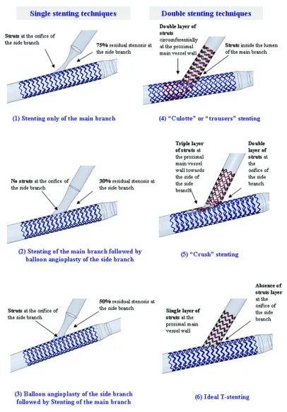
Six bifurcation stenting techniques were considered, three single stenting techniques and
three double stenting techniques:
(1) Stenting of the MB only
In this case of provisional stenting, one stent is implanted at the MB without any intervention
at the SB (Figure 2-1). Stenting of the MB results to introduction of a stent inside the
bifurcation lumen at the orifice of the SB. At the SB, we considered a symmetrical ostial
diameter stenosis of 75% affecting both the outer vessel wall and the flow divider.
(2) Stenting of the MB followed by balloon angioplasty of the SB
In this case of provisional stenting, one stent is implanted at the MB and then a balloon is
inflated at the SB through the struts of the MB stent (Figure 2-2). Balloon inflation removes
the stent struts from the orifice of the SB, thus there are no struts inside the lumen at the
bifurcation site. At the SB we considered a residual diameter stenosis of 30% since
angiographic success is frequently defined as achievement of <50% residual stenosis by any
percutaneous method.19
(3) Balloon angioplasty of the SB followed by stenting of the MB
Balloon angioplasty of the SB precedes stenting of the MB (Figure 2-3). After balloon
inflation and stent implantation there is usually a residual stenosis at the SB (considered 50%)
due to the combined effect of plaque shifting from the proximal segment of the MB, and
displacement of the flow divider by the expanded stent struts. Since stenting of the MB
follows balloon angioplasty of the SB, at the bifurcation site there are stent struts inside the
lumen at the orifice of the SB.
(4) “Culotte” stenting
“Culotte” or “trousers” stenting consists of implanting a first stent from the proximal to the
SB through the struts of the first stent (Figure 2-4). Culotte stenting results in a double layer
of struts in the proximal part of the MB and presence of struts in the lumen of the MB at the
bifurcation site.20We assumed that after stent implantation there is no residual narrowing at the MB or SB.
(5) “Crush” stenting
“Crush” stenting consists of advancing two stents simultaneously into both the MB and SB.
The proximal segment of the SB stent is first deployed in the MB and then it is crushed to the
main vessel wall during deployment of the MB stent (Figure 2-5). Crush stenting results in a
triple layer of struts in the proximal MB wall towards the branching vessel, and a double
layer of struts (from the MB stent and the crushed SB stent) at the orifice of the SB.20We assumed that after stent implantation there is no residual narrowing to either the MB or SB.
(6) Ideal T-stenting
This hypothetical stenting technique simulates an “idealized” T-stenting method in which one
stent is implanted at the MB and one stent at the SB while there is no strut overlap at any site
of the bifurcation and additionally the struts at the orifice of the SB have been intentionally
removed (Figure 2-6). This model was included in order to consider it as the “gold standard”
of bifurcation scaffolding.
CFD methodology and evaluation of simulations results
The simulations were conducted using the commercial software ANSYS FLUENT 12.1 (by
Fluent Inc.) The numerical grid for the simulation was created from the constructed
geometries using ANSYS Meshing 12.1 (by Fluent Inc.). The grid density was greatly
enhanced in the region around the stents. The total number of elements varied for the cases
examined from 2.7 to 4.5 million elements approximately. The following assumptions were
made:
The artery walls are assumed rigid and no deformation is taken into account
The simulation was transient covering 2 complete cardiac cycles. Results are
presented for the 2ndcycle. A total of 102 time steps per cardiac cycles were simulated
At the inlet, a pre-described pulse of the blood flow rate and pressure has been
assumed21
Mass flow exit boundary conditions were used for the 2 branches. The flow was
assumed to split proportionally to the (3/2) power of the bifurcation vessel’s normal
diameters
The hemodynamic parameters that were assessed at stented coronary bifurcations through
CFD simulations were the time averaged wall shear stress (TAWSS), the oscillatory shear
index (OSI) and the relative residence time (tr).TAWSSexpresses the frictional force per unit
area that is exerted by the flowing blood to the vascular wall due to the viscous properties of
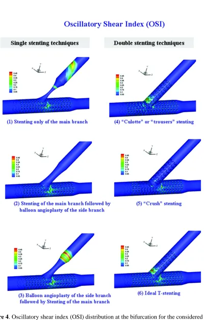
blood.22OSIis a dimensionless parameter that accounts for the degree of deviation of WSS from the antegrade flow direction. Small OSI values (close to 0) indicate small variations of
the WSS vector during the cardiac cycle. Conversely, OSI values close to 0.5 indicate that
WSS vector is subject to large variations and WSS can be very small or change direction at
parts of the cardiac cycle, which means that at those time instances flow is stopped or
reversed.23Although OSI can identify regions of flow reversal, it is insensitive to shear magnitude thus it has been suggested that OSI should be employed in combination with other
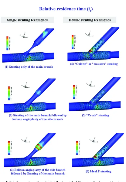
shear measures.24A relevant suitable index of flow is therelative residence timederived from TAWSS and OSI by the equationtr
12OSI
TAWSS
1.24Studies at stented coronary segments have shown that neointimal growth is located at regions of low WSS andhigh temporal oscillations in WSS quantified by high OSI.25The atherosclerotic process is also enhanced at areas at which the solutes and formed elements of blood have high residence
impact on many processes involved in thrombus formation, including platelet recruitment to
the vessel wall, platelet adhesion activation and aggregation.10Thrombus formation is enhanced at areas of slow and reversed flow characterized by high OSI and high residence
times since these conditions enhance platelet aggregation.9 In this study the bifurcation stenting techniques were comparatively evaluated in terms of the induced flow alterations at
the region of the bifurcation. Although we cannot directly link hemodynamic disturbances
and the risk of restenosis and thrombosis, it is plausible that the risk of restenosis and
thrombosis would be higher if regions of the bifurcation are continuously exposed to low
WSS or high OSI and tr. Thus, high TAWSS, low OSI and low trvalues were considered
hemodynamically favorable regarding the predisposition of each technique to restenosis and
thrombosis. TAWSS, OSI and trwere calculated as previously described.11, 24
Results
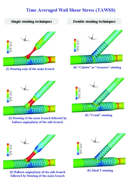
Figures 3, 4 and 5 give the TAWSS, OSI and trdistributions for the six considered stenting
techniques. These figures clearly demonstrate that each stenting technique has a distinct
impact to the flow patterns that is reflected both at the distribution and the magnitude of the
calculated flow indices to the bifurcation region.
Single stenting
At the three single stenting techniques (left panel of Figures 3-5) there is residual stenosis at
the SB through which flow is accelerated resulting to high flow velocities and thus WSS
values at this vessel. At the MB the distributions of WSS, OSI and tr are identical for the
three single stenting techniques, with a region of low WSS and high OSI and trvalues at the
distal MB, downstream the bifurcation. At the SB the distributions of WSS differ; at the cases
of tight residual stenosis high WSS values are seen at the whole stenotic region whereas
when the stenosis becomes less tight high WSS values are localized only close at the throat of
to the bifurcation, indicating that due to the flow acceleration there is no stagnation or
reversal of flow at this site. We can thus derive that in single stenting, flow patterns are
governed by the degree of the residual stenosis, whereas the existence or absence of stent
struts at the orifice of the SB do not impose any significant flow alterations.
Double stenting
With double stenting techniques (right panel of Figures 3-5), WSS, OSI and tr distributions
exhibit pronounced differences among cases. Culotte stenting results at low WSS regions at
both the proximal and the distal MB whereas with the other two double stenting techniques,
low WSS regions are confined to the distal MB. Regarding the SB, culotte stenting results at
an extended region of low WSS opposite the flow divider. With T-stenting the low WSS
region is considerably smaller, whereas with crush stenting there are no low WSS regions at
the SB. The distributions of OSI and tralso differ among stenting techniques; with culotte and
T-stenting, ‘hot spots’ of OSI are seen at the proximal SB, opposite the flow divider, whereas
with crush stenting the OSI distribution at the SB is smooth. At all cases small regions of
high OSI are seen at the distal MB which coincide with the regions of low WSS. Regarding
tr, more distinct differences among cases are seen; in culotte stenting the are ‘hot spots’ both
at the SB opposite the flow divider and at the proximal MB. At T-stenting there are ‘hot
spots’ at the both the SB and the distal MB whereas at crush stenting ‘hot spots’ are confined
to the SB and occupy considerably less area.
Comparison of techniques
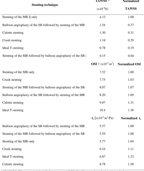
In order to compare findings, we calculated the surface integrals of TAWSS, OSI and trat a
subregion of bifurcation site (Figure 1). The integral of each index was normalized to that of
the stenting technique that provided the most hemodynamically favorable results, eg highest
TAWSS, and lowest OSI and tr(Table 1). The ranking of the stenting techniques in Table 1
Table 1 we can derive that single stenting techniques and particularly stenting of the MB only
and balloon angioplasty of the SB followed by stenting of the MB, give better overall results
compared to the double stenting techniques. Among the double stenting techniques, crush
stenting gives the most favorable results while its overall ranging follows the two optimum
single stenting techniques.
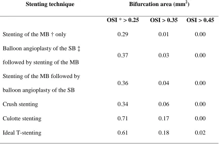
Additionally, we calculated for each stenting technique the total area of the
bifurcation region that is subjected to OSI values greater than specific predefined thresholds
(Table 2). As previously noted, OSI values close to 0.5 indicate arterial segments of flow
stagnation or flow reversal. The results shown in Table 2 indicate that single stenting
techniques result in smaller arterials segments at which flow is stopped or reversed. Crush
stenting gives the optimum results among the double stenting techniques, which are
comparable to those of single stenting techniques.
Discussion
Our results indicate that double stenting in bifurcations is associated with disturbed
hemodynamics. They also indicate that double stenting techniques do not produce similar
hemodynamic disturbances at bifurcations. Plaque and neointimal hyperplasia tend to form in
bifurcations within the coronary arteries where normal patterns of blood flow are disturbed.27 Even when proliferative responses to these altered hemodynamics are completely blocked by
drug-eluting stents, abnormal flow patterns can be a possible cause of thrombosis.28A number of computational studies have assessed hemodynamic alterations produced by stent
implantation at non-bifurcated vessel segments: LaDisa et al13 studied WSS alterations after a slotted-tube coronary stent and found that flow stagnation zones are localized around the
stent struts and minimum WSS decreased by 77% in stented compared to non-stented vessels.
following struts that are perpendicular to the main flow direction. Data regarding flow
alterations caused by stent implantation at bifurcation lesion is limited. A computational
study by Williams et al6assessed hemodynamic changes after main branch stenting and side branch balloon angioplasty in a coronary bifurcation and indicated that this commonly used
interventional strategy causes abnormal local hemodynamic conditions.
Our study, is the first one to investigate flow patterns following different stenting
techniques at bifurcation sites. Although the findings of the study refer to the hemodynamic
disturbances imposed by stenting which cannot be directly linked to the clinical outcome, it is
plausible that the risk of restenosis and thrombosis would be higher at regions of the
bifurcation that are continuously exposed to unfavorable hemodynamic conditions. In a
recent study at specimens of stented bifurcations of patients dying of severe coronary artery
disease, Nakazawa et al30reported that neointimal formation is significantly less at the flow divider compared with the lateral wall and that late stent thrombosis has a higher prevalence
at flow divider sites due to uncovered struts and disturbed flow at the carina region. Our
computational findings are in part in keeping with these observations since in all simulated
stenting techniques, regions of low WSS and high OSI which are both associated to
neointimal formation, are confined at the lateral arterial walls. Regarding stent thrombosis,
our results indicate that the bifurcation regions at higher risk of thrombosis generally coincide
with the regions of neointimal formation and are located opposite the flow divider. This
difference is probably due to the fact that our study did not consider strut coverage by
neointimal formation. Thus, considering the results of both studies, one might speculate that
the risk of acute stent thrombosis is higher at sites opposite the flow divider whereas the risk
of late thrombosis is higher at the carina region.
Regarding the comparison of single and double stenting techniques, our findings are in
main vessel is preferable in the great majority of bifurcation lesions.1, 2A recent clinical trial comparing double kissing (DK) crush with provisional stenting for the treatment of
bifurcation lesions demonstrated that DK crush is associated with significant reduction of
target lesion and target vessel revascularization, whereas there was not significant difference
in major adverse cardiac events.4Interestingly, in our study crush stenting was associated with the most favorable hemodynamic conditions among double stenting techniques which
were in some cases comparable to those imposed by single stenting. Surprisingly, the
considered ‘ideal’ T-stenting evaluated in the study which theoretically provides optimum
bifurcation scaffolding since it covers the bifurcation region without strut overlap or strut
protrusion into the vessel lumen produced overall the worst results from a hemodynamic
perspective. However, in clinical practice, the NORDIC investgators failed to detect any
difference between the culotte and crush techniques using a Cypher Select+ stent (Johnson
and Johnson).31Whether this can be attributed to the thicker struts of this stent cannot be deduced from our data. In theory, arterial segments covered with double layers of stents are
less prone to stent recoil due to the increased exerted radial force which counteracts more
effectively any recoil of the elastic vessel wall.32In our study, the only stenting technique in which part of the bifurcation is circumferentially covered with double layers of stents is the
“Culotte” technique which was however not associated with favour hemodynamic results.
Nevertheless, both phenomena of restenosis and thrombosis are complex and multifactorial
and the effect of stent recoil cannot be neglected.
Study limitations
The considered model represents an idealized coronary bifurcation with vessel dimensions
and bifurcation angle of a typical left anterior – diagonal branch bifurcation. At the SB we
considered an ostial symmetrical stenosis, affecting both the outer vessel wall and the flow
or radially. However, although early atherosclerosis is localized at sites of low wall shear
stress (WSS) such as the outer walls of vessel bifurcations,33at advanced to severe
atherosclerosis, plaques grow circumferentially from the low WSS region into the high WSS
flow divider,34thus severe ostial stenoses become circumferentially symmetric. Additionally, ostial stenoses of side branches are commonly aggravated after MB stent implantation due to
the combined effect of plaque shifting from the proximal segment of the MB into the SB
ostium35and displacement of the flow divider by the expanded stent struts (carina displacement between the two diverging branches).36The MB and SB were considered straight, non-compliant and stationary although coronary vessels are curved, compliant and
attached to the beating myocardium. Studies have shown that myocardial motion has only a
minor effect on flow distribution within the arterial tree relative to the effect of the blood
pressure pulse37and stent implantation causes straightening of the vessel and reduces its regional compliance.38Regarding the assumptions of the flow simulation, the boundary conditions were similar to most relevant studies and included realistic pulsatile flow and
pressure, whereas blood was considered Newtonian, and this is not applicable to all flow
conditions. However, this assumption has been shown to have minor effect on the distribution
of the flow parameters assessed in this study.39
Acknowledging these limitations, our data indicate that single stenting of the main
branch with our without balloon angioplasty of the side branch ostium, offers better
hemodynamic patterns than double stenting. When double stenting is considered necessary,
the crush technique with the use of a thin strut stent is preferable to culotte or T stenting.
Whether these theoretical advantages translate into improved clinical outcomes cannot be
deduced from our study.
Dr Katritsis has received research grants from Boston Scientific, Medtronic, and Johnson and
References
1. Behan MW, Holm NR, Curzen NP, Erglis A, Stables RH, de Belder AJ, Niemela M,
Cooter N, Chew DP, Steigen TK, Oldroyd KG, Jensen JS, Lassen JF, Thuesen L,
Hildick-Smith D. Simple or complex stenting for bifurcation coronary lesions: A
patient-level pooled-analysis of the nordic bifurcation study and the british bifurcation
coronary study.Circulation. 2011;4:57-64
2. Katritsis DG, Siontis GC, Ioannidis JP. Double versus single stenting for coronary
bifurcation lesions: A meta-analysis.Circulation. 2009;2:409-415
3. Latib A, Colombo A, Sangiorgi GM. Bifurcation stenting: Current strategies and new
devices.Heart (British Cardiac Society). 2009;95:495-504
4. Chen SL, Santoso T, Zhang JJ, Ye F, Xu YW, Fu Q, Kan J, Paiboon C, Zhou Y, Ding
SQ, Kwan TW. A randomized clinical study comparing double kissing crush with
provisional stenting for treatment of coronary bifurcation lesions results from the
dkcrush-ii (double kissing crush versus provisional stenting technique for treatment of
coronary bifurcation lesions) trial.Journal of the American College of Cardiology.
2011;57:914-920
5. Onuma Y, Serruys PW. Bioresorbable scaffold: The advent of a new era in
percutaneous coronary and peripheral revascularization?Circulation.
2011;123:779-797
6. Williams AR, Koo BK, Gundert TJ, Fitzgerald PJ, Ladisa J, Jr. Local hemodynamic
changes caused by main branch stent implantation and virtual side branch balloon
angioplasty in a representative coronary bifurcation.J Appl Physiol.
7. Garasic JM, Edelman ER, Squire JC, Seifert P, Williams MS, Rogers C. Stent and
artery geometry determine intimal thickening independent of arterial injury.
Circulation. 2000;101:812-818
8. Kastrati A, Mehilli J, Dirschinger J, Pache J, Ulm K, Schuhlen H, Seyfarth M,
Schmitt C, Blasini R, Neumann FJ, Schomig A. Restenosis after coronary placement
of various stent types.The American journal of cardiology. 2001;87:34-39
9. Bluestein D, Gutierrez C, Londono M, Schoephoerster RT. Vortex shedding in steady
flow through a model of an arterial stenosis and its relevance to mural platelet
deposition.Annals of biomedical engineering. 1999;27:763-773
10. Nesbitt WS, Mangin P, Salem HH, Jackson SP. The impact of blood rheology on the
molecular and cellular events underlying arterial thrombosis.Journal of molecular
medicine (Berlin, Germany). 2006;84:989-995
11. Katritsis DG, Theodorakakos A, Pantos I, Andriotis A, Efstathopoulos EP, Siontis G,
Karcanias N, Redwood S, Gavaises M. Vortex formation and recirculation zones in
left anterior descending artery stenoses: Computational fluid dynamics analysis.
Physics in medicine and biology. 2010;55:1395-1411
12. Moore JE, Jr., Timmins LH, Ladisa JF, Jr. Coronary artery bifurcation biomechanics
and implications for interventional strategies.Catheter Cardiovasc Interv.
2010;76:836-843
13. LaDisa JF, Jr., Guler I, Olson LE, Hettrick DA, Kersten JR, Warltier DC, Pagel PS.
Three-dimensional computational fluid dynamics modeling of alterations in coronary
wall shear stress produced by stent implantation.Annals of biomedical engineering.
14. Lefevre T, Louvard Y, Morice MC, Dumas P, Loubeyre C, Benslimane A, Premchand
RK, Guillard N, Piechaud JF. Stenting of bifurcation lesions: Classification,
treatments, and results.Catheter Cardiovasc Interv. 2000;49:274-283
15. Di Mario C, Morici N, Godino C, Goktekin O, Tamburino C, Barbagallo R,
Antoniucci D, Grube E, Airoldi F, Zoccai GB, Colombo A, Sangiorgi GM. Predictors
of restenosis after treatment of bifurcational lesions with paclitaxel eluting stents: A
multicenter prospective registry of 150 consecutive patients.Catheter Cardiovasc
Interv. 2007;69:416-424
16. Finet G, Gilard M, Perrenot B, Rioufol G, Motreff P, Gavit L, Prost R. Fractal
geometry of arterial coronary bifurcations: A quantitative coronary angiography and
intravascular ultrasound analysis.EuroIntervention. 2008;3:490-498
17. Dzavik V, Kharbanda R, Ivanov J, Ing DJ, Bui S, Mackie K, Ramsamujh R, Barolet
A, Schwartz L, Seidelin PH. Predictors of long-term outcome after crush stenting of
coronary bifurcation lesions: Importance of the bifurcation angle.American heart
journal. 2006;152:762-769
18. Wilson GJ, Huibregtse BA, Stejskal EA, Crary J, Starzyk RM, Dawkins KD, Barry JJ.
Vascular response to a third generation everolimus-eluting stent.EuroIntervention.
2010;6:512-519
19. Colombo A, Moses JW, Morice MC, Ludwig J, Holmes DR, Jr., Spanos V, Louvard
Y, Desmedt B, Di Mario C, Leon MB. Randomized study to evaluate
sirolimus-eluting stents implanted at coronary bifurcation lesions.Circulation.
2004;109:1244-1249
20. Louvard Y, Lefevre T, Morice MC. Percutaneous coronary intervention for
bifurcation coronary disease.Heart (British Cardiac Society). 2004;90:713-722
22. Katritsis D, Kaiktsis L, Chaniotis A, Pantos J, Efstathopoulos EP, Marmarelis V. Wall
shear stress: Theoretical considerations and methods of measurement.Progress in
cardiovascular diseases. 2007;49:307-329
23. He X, Ku DN. Pulsatile flow in the human left coronary artery bifurcation: Average
conditions.Journal of biomechanical engineering. 1996;118:74-82
24. Himburg HA, Grzybowski DM, Hazel AL, LaMack JA, Li XM, Friedman MH.
Spatial comparison between wall shear stress measures and porcine arterial
endothelial permeability.American journal of physiology. 2004;286:H1916-1922
25. Wentzel JJ, Gijsen FJ, Schuurbiers JC, van der Steen AF, Serruys PW. The influence
of shear stress on in-stent restenosis and thrombosis.EuroIntervention. 2008;4 Suppl
C:C27-32
26. Moore JE, Jr., Ku DN, Zarins CK, Glagov S. Pulsatile flow visualization in the
abdominal aorta under differing physiologic conditions: Implications for increased
susceptibility to atherosclerosis.Journal of biomechanical engineering.
1992;114:391-397
27. Stone PH, Coskun AU, Kinlay S, Clark ME, Sonka M, Wahle A, Ilegbusi OJ,
Yeghiazarians Y, Popma JJ, Orav J, Kuntz RE, Feldman CL. Effect of endothelial
shear stress on the progression of coronary artery disease, vascular remodeling, and
in-stent restenosis in humans: In vivo 6-month follow-up study.Circulation.
2003;108:438-444
28. Chatzizisis YS, Coskun AU, Jonas M, Edelman ER, Feldman CL, Stone PH. Role of
endothelial shear stress in the natural history of coronary atherosclerosis and vascular
remodeling: Molecular, cellular, and vascular behavior.Journal of the American
29. Faik I, Mongrain R, Leask RL, Rodes-Cabau J, Larose E, Bertrand O.
Time-dependent 3d simulations of the hemodynamics in a stented coronary artery.
Biomedical materials (Bristol, England). 2007;2:S28-37
30. Nakazawa G, Yazdani SK, Finn AV, Vorpahl M, Kolodgie FD, Virmani R.
Pathological findings at bifurcation lesions: The impact of flow distribution on
atherosclerosis and arterial healing after stent implantation.Journal of the American
College of Cardiology. 2010;55:1679-1687
31. Erglis A, Kumsars I, Niemela M, Kervinen K, Maeng M, Lassen JF, Gunnes P,
Stavnes S, Jensen JS, Galloe A, Narbute I, Sondore D, Makikallio T, Ylitalo K,
Christiansen EH, Ravkilde J, Steigen TK, Mannsverk J, Thayssen P, Hansen KN,
Syvanne M, Helqvist S, Kjell N, Wiseth R, Aaroe J, Puhakka M, Thuesen L.
Randomized comparison of coronary bifurcation stenting with the crush versus the
culotte technique using sirolimus eluting stents: The nordic stent technique study.
Circulation. 2009;2:27-34
32. Williams PD, Appleby CE, Chowdhary S, Fraser DG. Double stenting: A method for
treating acute stent recoil and luminal filling defects.EuroIntervention.6:846-853
33. Malek AM, Alper SL, Izumo S. Hemodynamic shear stress and its role in
atherosclerosis.Jama. 1999;282:2035-2042
34. van der Giessen AG, Wentzel JJ, Meijboom WB, Mollet NR, van der Steen AF, van
de Vosse FN, de Feyter PJ, Gijsen FJ. Plaque and shear stress distribution in human
coronary bifurcations: A multislice computed tomography study.EuroIntervention.
2009;4:654-661
35. Koo BK, Waseda K, Kang HJ, Kim HS, Nam CW, Hur SH, Kim JS, Choi D, Jang Y,
Hahn JY, Gwon HC, Yoon MH, Tahk SJ, Chung WY, Cho YS, Choi DJ, Hasegawa
evaluation of bifurcation lesions undergoing percutaneous coronary intervention.
Circulation. 2010;3:113-119
36. Vassilev D, Gil R. Clinical verification of a theory for predicting side branch stenosis
after main vessel stenting in coronary bifurcation lesions.Journal of interventional
cardiology. 2008;21:493-503
37. Theodorakakos A, Gavaises M, Andriotis A, Zifan A, Liatsis P, Pantos I,
Efstathopoulos EP, Katritsis D. Simulation of cardiac motion on non-newtonian,
pulsating flow development in the human left anterior descending coronary artery.
Physics in medicine and biology. 2008;53:4875-4892
38. LaDisa JF, Jr., Hettrick DA, Olson LE, Guler I, Gross ER, Kress TT, Kersten JR,
Warltier DC, Pagel PS. Stent implantation alters coronary artery hemodynamics and
wall shear stress during maximal vasodilation.J Appl Physiol. 2002;93:1939-1946
39. Johnston BM, Johnston PR, Corney S, Kilpatrick D. Non-newtonian blood flow in
human right coronary arteries: Transient simulations.Journal of biomechanics.
Figures
Figure 1. The considered model of a typicalleft anterior descending – diagonal bifurcation. The
rectangle denotes the bifurcation subregion at which the surface integrals of the flow indices
Figure 2. Considered bifurcation stenting techniques and they effect on stent strut
distribution on the vessel wall and vessel lumen. The left panel illustrates the single stenting
Figure 3. Time averaged wall shear stress (TAWSS) distribution at the bifurcation for the
Figure 4. Oscillatory shear index (OSI) distribution at the bifurcation for the considered
Figure 5. Relative residence time (tr) distribution at the bifurcation for the considered
Table 1. Surface integrals of the flow indices for the six considered stenting techniques and
normalized integrals to the technique that provided optimum result.
*TAWSS: Time averaged wall shear stress, †OSI: Oscillatory shear index, ‡tr: relative
residence time, §MB: main branch, |SB: side branch Stenting technique
TAWSS*
(x10-4N)
Normalized
TAWSS
Stenting of the MB§only 4.13 1.00
Balloon angioplasty of the SB followed by stenting of the MB 1.54 0.37
Culotte stenting 1.30 0.31
Crush stenting 1.18 0.29
Ideal T-stenting 0.78 0.19
Stenting of the MB followed by balloon angioplasty of the SB| 0.15 0.04
OSI†(x10-6m2) Normalized OSI
Stenting of the MB only 7.52 1.00
Crush stenting 7.75 1.03
Stenting of the MB followed by balloon angioplasty of the SB 8.07 1.07
Balloon angioplasty of the SB followed by stenting of the MB 8.20 1.09
Culotte stenting 9.87 1.31
Ideal T-stenting 10.4 1.38
tr‡(x10-4m2/Pa) Normalized tr
Balloon angioplasty of the SB followed by stenting of the MB 5.57 1.00
Stenting of the MB followed by balloon angioplasty of the SB 5.59 1.00
Stenting of the MB only 5.77 1.04
Crush stenting 6.16 1.11
Ideal T-stenting 6.87 1.23
Table 2. Bifurcation total area in which OSI exhibits values greater than specific thresholds.
Stenting technique Bifurcation area (mm2)
OSI*> 0.25 OSI > 0.35 OSI > 0.45
Stenting of the MB † only 0.29 0.01 0.00
Balloon angioplasty of the SB ‡
followed by stenting of the MB
0.37 0.03 0.00
Stenting of the MB followed by
balloon angioplasty of the SB
0.36 0.04 0.00
Crush stenting 0.34 0.06 0.00
Culotte stenting 0.71 0.17 0.00
Ideal T-stenting 0.61 0.18 0.02