UNIVERSITI TEKNIKAL MALAYSIA MELAKA
PROCESS OPTIMIZATION FOR DIE MANUFACTURE: EDM
DIE SINKING
This report submitted in accordance with requirement of the UniversitiTeknikal Malaysia Melaka (UTeM) for the Bachelor Degree of Manufacturing Engineering
(Degree of Manufacturing Process)(Hons.)
By
MOHD IRWAN BIN JAINUDIN B051010074
890102-01-6239
UNIVERSITI TEKNIKAL MALAYSIA MELAKA
BORANG PENGESAHAN STATUS LAPORAN PROJEK SARJANA MUDA
TAJUK:
PROCESS OPTIMIZATION FOR DIE MANUFACTURE: EDM
DIE SINKING
SESI PENGAJIAN: 2013/2014 SEMESTER 2
Saya MOHD IRWAN BIN JAINUDIN
mengaku membenarkan Laporan PSM ini disimpan di Perpustakaan Universiti Teknikal Malaysia Melaka (UTeM) dengan syarat-syarat kegunaan seperti berikut:
1. Laporan PSM adalah hak milik Universiti Teknikal Malaysia Melaka dan penulis.
2. Perpustakaan Universiti Teknikal Malaysia Melaka dibenarkan membuat salinan
untuk tujuan pengajian sahaja dengan izin penulis.
3. Perpustakaan dibenarkan membuat salinan laporan PSM ini sebagai bahan
pertukaran antara institusi pengajian tinggi. 4. **Sila tandakan (√)
SULIT
TERHAD
TIDAK TERHAD
(Mengandungi maklumat yang berdarjah keselamatan atau kepentingan Malaysiasebagaimana yang termaktub dalam AKTA RAHSIA RASMI 1972)
(Mengandungi maklumat TERHAD yang telah ditentukan oleh organisasi/badan di mana penyelidikan dijalankan)
Alamat Tetap:
No9, Jln Bunga Raya Besar,
Kg Dato Sulaiman Menteri,
Majidee Baru, 81100 Johor Bahru,
Johor.
Tarikh: _________________________
Disahkan oleh:
Cop Rasmi:
Tarikh: _______________________
DECLARATION
I hereby, declared this report entitled “Process Optimization for Die Manufacture: EDM Die Sinking” is the results of my own research except as cited in references.
Signature : ………
APPROVAL
This report is submitted to the Faculty of Manufacturing Engineering of UTeM as a partial fulfillment of the requirements for the degree of Bachelor of Manufacturing Engineering (Process) (Hons.). The supervisor is as follow:
i ABSTRAK
ii ABSTRACT
iii
DEDICATION
iv
ACKNOWLEDGEMENT
A special thanks to my supervisor, Dato’ Prof. Dr. Abu b. Abdullah for this supervision in doing this project. I greatly appreciate his consistent encouragement, advice and invaluable guidance throughout the project.
I wish to extend my special appreciation to Mr. Hanafiah and Mr. Taufik and also all staff and technicians for their patience, support and comment.
v
TABLE OF CONTENT
Abstrak i
Abstract ii
Dedication iii
Acknowledgement iv
Table of Content v
List of Tables ix
List of Figures xi
CHAPTER 1: INTRODUCTION 1
1.1 Background 1
1.2 Problem Statement 2
1.3 Objectives 3
1.4 Scope of Work 3
CHAPTER 2: LITERATURE REVIEW 4
2.1 Machining 4
2.2 Traditional Machining 5
2.2.1 Machining by Cutting 6
2.2.2 Machining by Abrasion 8
2.3 Non-Traditional Machining 9
2.3.1 Single-Action Non-Traditional Machining 10
2.3.1.1 Mechanical Machining 10
vi 2.3.1.3 Chemical and Electrochemical Machining 12
2.4 Electro Discharge Machining (EDM) 13
2.4.1 EDM Die-Sinking 14
2.4.2 Working Principle of EDM 15
2.4.3 The Machining System 18
2.4.4 Dielectric Fluid 19
2.4.5 Flushing 20
2.4.5.1 Normal Flow 20
2.4.5.2 Reverse Flow 21
2.4.5.3 Jet Flushing 21
2.4.5.4 Immersion Flushing 21
2.5 Advantages and disadvantages of EDM die-sinking 22
2.6 Applications 22
2.6.1 Drilling 23
2.6.2 Sawing 23
2.6.3 Machining of Spheres 24
2.6.3 Machining of Dies and Mold 24
2.7 EDM Electrode 25
2.7.1 Brass 25
2.7.2 Copper 26
2.8 Material of Workpieces 28
2.8.1 SKD11 (Alloy Tool Steel) 28
vii
2.10 Machining Performance 30
2.10.1 Material Removal Rate (MRR) 30
2.10.2 Surface Roughness (Ra) of Workpieces 31
CHAPTER 3: METHODOLOGY 32
3.1 Flow Chart 32
3.2 Specimen Preparation 35
3.3 Electrode Preparation 36
3.4 Machine and Measurement Equipment 37
3.4.1 EDM Wire Cut Machine 37
3.4.2 EDM Die-Sinking Machine 37
3.4.3 Surface Roughness Measurement 39
3.5 Design of Experiment and Data Analysis 39
CHAPTER 4: RESULTS AND DISCUSSIONS 45
4.1 Experimental Matrix and Experimental Result of the EDM Parameters 45
4.1.1 Process control parameters 45
4.1.2 Design Matrix of Process Control Parameters and the Response 46
4.1.3 The Surface Microstructure 48
4.2 Analysis of the EDM Parameters to Surface Roughness and Material Removal
Rate 49
4.2.1 Surface Roughness Ra 51
viii 4.2.1.2 Determine Optimum Factor-Level Combination 52
4.2.1.3 Optimize Performance for Ra 53
4.2.2 Material Removal Rate MRR 55
4.2.2.1 Analysis of Variance for MRR 55
4.2.2.2 Determine Optimum Factor-Level Combination 56
4.2.2.3 Optimize Performance for Ra 57
CHAPTER 5: CONCLUSIONS AND RECOMMENDATION 59
5.1 Conclusions 59
5.2 Recommendation 60
REFERENCE 61
APPENDIX
ix
LIST OF TABLE
3.1 3.2 3.3 3.4 3.5 3.6 3.7 4.1 4.2 4.3 4.4 4.5 4.6 4.7 4.8 4.9 4.10
Mechanical Properties for SKD11 at Ambient Temperature and Elevated Temperatures. (www.uddeholm.com)
Density and melting point for copper and brass
Constant Input Parameter
Machining Parameter of This Project
The Test Runs Parameter
MIXED DESIGN L8 Orthogonal array with S/N ratio for the MRR
MIXED DESIGN L8 Orthogonal array with S/N ratio for the Ra
Detail process control parameters
Design matrix of process control parameters and the response
Mixture design L8 orthogonal array with S/N ratio for the Ra and MRR
Response Table for Signal to Noise Ratios Smaller is better (Ra analysis)
Response Table for Means (Surface roughness analysis)
Response Table for Signal to Noise Ratios Larger is better (MRR analysis)
Response Table for Means (MRR analysis)
Linear Model Analysis: SN ratios versus tool, peak current, pulse-on time
Linear Model Analysis: Means versus tool, peak current, pulse-on time
Estimated Model Coefficients for Means
x 4.11
4.12
4.13
Linear Model Analysis: SN ratios versus tool, peak current, pulse-on time
Linear Model Analysis: Means versus tool, peak current, pulse-on time
Estimated Model Coefficients for Means
55
55
xi
LIST OF FIGURE
2.1 2.2 2.3 2.4 2.5 2.6 2.7 2.8 2.9 2.10 2.11 2.12 2.13 2.14 2.15 2.16 2.17
Material removal processes. (El-Hofy, 2005)
Metal cutting processes. (El-Hofy, 2005)
Abrasive machining. (El-Hofy, 2005)
Non-traditional machining processes. (El-Hofy, 2005)
Mechanical machining processes. (El-Hofy, 2005)
Thermal non-conventional processes. (El-Hofy, 2005)
Electrochemical and Chemical Machining Processes.
Basic EDM System
Working principle of EDM (Kuldeep Ojha, R. K. Garg, K. K. Singh, 2010)
Variation of capacitor voltage with time in RC circuit. (McGeough, 1988)
Schematic view of discharge gap (Kuneida, M., Lauwers, B., Rajurkar, K.P., Schumacher, B.M., 2005)
EDM schematic. (El-Hofy, 2005)
EDM system components. (El-Hofy, 2005)
Common dielectric flushing modes. (El-Hofy, 2005)
EDM Sawing Schematic. (El-Hofy, 2005)
Rotary EDM. (El-Hofy, 2005)
EDM Die Milling. (El-Hofy, 2005)
xii 2.18 3.1 3.2 3.3 3.4 3.5 3.6 3.7 3.8 3.9 3.10 4.1 4.2 4.3 4.4 4.5 4.6 4.7
Chemical Compositions of SKD11
Process Flow Chart for Project Experiment
Process Flow Chart for Experiment
Dimension of workpiece
Dimension of electrode
Mitsubishi (RA90) Wire Cut machine (www.agtedmmfg.com)
SODICK (AQ35L) EDM Die-sinking Machine
MITUTOYO (SJ310) (www.acklandsgrainger.com)
Type of Design and Number of Factors Selected
Chosen Number of Run (L9 Orthogonal Array)
Name of Factors and Level Values are Inserted
Graph of surface roughness
Graph of material removal rate
Comparison of surface microstructure for specimen number 9 and specimen number 11
Main Effects Plot for SN Ratios (Surface roughness analysis)
Main Effects Plot for Means (Surface roughness analysis)
Main Effects Plot for SN Ratio (MRR analysis)
Main Effects Plot for Means (MRR analysis)
1
1.1 Background
Electrical discharge machining (EDM) is a non-traditional manufacturing process based on removing material from a part by means of a series of repeated electrical discharge between tools called the electrode on the part being machined in the presence of an electric fluid. At present, EDM is widespread technique used in industry for high precision machining of all types of conductive materials such as metals, metallic alloys, graphite, or even some ceramics material of any hardness (C.J. Luis et al.2005). In tool die and mould making industries, EDM is commonly used for machining heat treated tool steels materials.
EDM also manufacturing process based the erosion of metals sparks discharges. Shaped tool or known as electrode and the workpiece are the basics EDM system which connected to a DC power supply and place in a die electric. The sparks in this process erode away the electrode, thus changing its geometry and adversely affecting the shape produced and its dimensional accuracy. Tool (electrode) wear is thus an important factor which is related to the melting point of the electrode of the materials involved.
EDM has a high capability of machining the accurate cavities of dies and moulds. Nevertheless, electrode wear occurs during EDM process leading to a lack of machining accuracy in the geometry of workpiece. Furthermore, electrode wear
2 imposes high costs on manufacturers to substitute the eroded complicated electrodes by new ones for die making. In order to increase the machining efficiency, erosion of the workpiece must be maximized and that of the electrode minimized in EDM process (H. Zarepour et al. 2007).
Normally, EDM is capable of machining geometrically complex or hard material component, that are precise and difficult to machine. These studies will investigate the performance of different electrode Materials on SKD11 workpiece with EDM process. The electrode materials were graphite, copper and Brass. The influences of some machining parameters such as pulsed current, pulse time, pulse pause time, voltage, dielectric liquid pressure and electrode material have been examined. This investigation will be done through a several experiments between electrode and workpiece to identify an effect of process parameter. The response factors that want to observe is more to surface roughness (Ra) and material removal rate (MRR).
1.2 Problem Statement
This study is focusing on following questions:
a) What is the most suitable electrode for machining of SKD11 material between Cooper and Brass electrode that gives best result of surface roughness using same parameter?
b) What is the machining parameters for each type of electrode (peak current and pulse-on time) that influence the surface roughness (Ra) and material
3
1.3 Objectives
The objectives of this project are:
a) To investigate the most suitable electrode to machining SKD11 material between copper and brass electrode.
b) To study effect of surface roughness (Ra) and material removal rate (MRR) when using different type of electrode.
c) To study the parameter that will be optimized to get optimum result in surface roughness (Ra) and material removal rate (MRR)
1.4 Scope of Work
In order to get the best result, this experiment must be focused to the following issue:
i. Parameters to be studied include type of electrode, peak current and pulse on time (ON).
ii. Machining SKD11 material with using copper and brass electrode.
4
2.1 Machining
Machining is a material removal process in which a sharp cutting tool is used to mechanically cut away material so that the desired part geometry remains. The most common application: to shape metal parts. Machining is the most versatile and accurate of all manufacturing processes in its capability to produce a diversity of part geometries and geometric features. (M. P. Groover, 2002)
Machining is a term that covers a large collection of manufacturing processes designed to remove unwanted material, usually in the form of chips, from a workpiece. Machining is used to convert castings, forgings, or preformed blocks of metal into desired shapes, with size and finish specified to fulfil design requirements. Almost every manufactured product has components that require machining, often to great precision. Therefore, this collection of processes is one of the most important of the basic manufacturing processes because of the value added to the final product. By the same token, machining processes are often the most expensive. The majority of industrial applications of machining are in metals. Although the metal cutting process has resisted theoretical analysis because of its complexity, the application of these processes in the industrial world is widespread. Machining processes are performed on a wide variety of machine tools (J. T. Black, 1990).
Machining is a general term describing a group of processes that consist of the removal of material and modification of the surfaces of a workpiece after it has been
5 produced by various methods, thus machining involves secondary and finishing operations (Kalpakjian et al., 2010).
According to El-Hofy (2005) harder, stronger and tougher material that frequently used in modern machining practice are more difficult to machine. In modern machining practice, harder, stronger, and tougher materials that are more difficult to cut are frequently used. Nowadays, directed toward the machining process in which the mechanical properties of the workpiece material does not impose any limitations on material removal process. In this case, nonconventional machining techniques came into practice as the possible alternatives in the machine, design complexity, surface integrity, and the need downsizing.
2.2 Traditional Machining
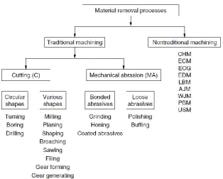
6 Figure 2.1: Material removal processes. (El-Hofy, 2005)
2.2.1 Machining by Cutting
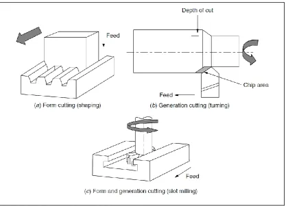
According to El-Hofy (2005) during machining with cutting, this tool penetrates the workpiece to the cutting depth. A relative motion (main and feed) to determine the geometry of the workpiece is required. In this case, the change resulted in the cylinder, shaping and milling produces flat surface while drilling produce different diameter holes. Tools have the cutting edge geometry is known. Action to cut waste machining allowance in the form of chips, which can be seen with the naked eye. During machining with cutting, the workpiece shape can be produced by forming when the cutting tool has finished workpiece contour. A relative motion is required to produce the chip (main motion) in addition to the tool feed in depth as shown in Figure 2.2a.
7 generation of the cutting surface. Milling the slot, as shown in Figure 2.2c, adopt the shape and cut principles combined generation. (El-Hofy, 2005)
Figure 2.2: Metal cutting processes. (El-Hofy, 2005)
Durability of the workpiece for machining with cutting depends on the temperature generated in the machining zone. Highspeed Hot Machining now recognized as one of the leading manufacturing techniques with high production. As the temperature increases, the strength decreased while the increase in ductility. It is quite logical to assume that the high temperature will reduce cutting forces and energy consumption and increase in material cutting machine. Hot Machining has been working to improve the machinability of glass and ceramic engineering. (El-Hofy, 2005)
8 milling centers. The laser beam was focused onto the workpiece material just above the machining zone. The laser-assisted turning reduced the cutting force and tool wear and improved the geometrical characteristics of the turned parts.
2.2.2 Machining by Abrasion
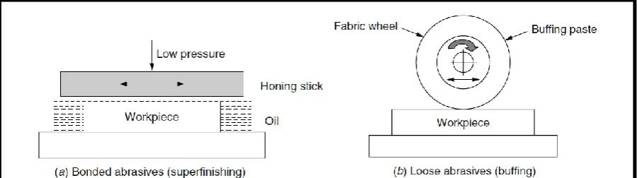
[image:24.595.115.565.500.626.2]According to El-Hofy (2005) abrasive machining term usually describes a process in which the provisions issued by various machining hard, angular abrasive particles or grains (also called grits), which may or may not be tied to a definite geometric shape tool. In contrast to metal cutting, abrasive machining, cutting edge individuals are randomly oriented and the depth of involvement (undeformed chip thickness) is small and not equal for all coarse grains at the same time in contact with the workpiece. Cutting edge (abrasive) is used to remove small machining allowance MA action during the finishing process. The material is removed in the form of minute chips, which are invisible in most cases. The MA action is adopted during grinding, honing, and super finishing processes that employ either solid grinding wheels or sticks in the form of bonded abrasives (Figure 2.3a). Furthermore, in lapping, polishing, and buffing, loose abrasives are used as tools in a liquid machining media as shown in Figure 2.3b.