University of Southern Queensland
Novel Fibre Composite Civil Engineering
Sandwich Structures: Behaviour, Analysis,
and Optimum Design
A Dissertation submitted by
Ziad Khalaf Awad
B.sc. Eng., M.sc. Eng.Supervised by
Assoc. Prof. Thiru Aravinthan
Dr. Yan Zhuge
For the award of
Abstract
Fibre reinforced polymer (FRP) composite sandwich structures are increasingly used in the construction of civil engineering applications because of their outstanding strength and light weight properties. However, the use of FRP products has some design difficulties as a result of the composition of the fibre and matrix. The design variables usually are fibre and matrix properties, fibre direction, laminate composition, and core thickness. The combination of the design variables leads to a complex design problem, and the optimisation of fibre composite sandwich structures is rarely straightforward. This is due to the complicated behaviour, and the multiple design variables and objectives required to be considered. This research deals with the presentation of a glass fibre reinforced polymer (GFRP) sandwich structure analysis and design. Based on the literature review, a design optimisation methodology was proposed for the FRP composite structures. The methodology contains three parts; experimental investigation, Finite Element Analysis (FEA) with modelling verification, and design optimisation of the GFRP sandwich structures.
Several experimental static and free vibration tests were made on the GFRP sandwich beams and slabs. The experimental investigation provided good information about understanding the behaviour of the GFRP sandwich structures. A user subroutine UMAT was written to model the GFRP sandwich skins in three dimensions (3D) FEA. The FEA model was verified with the structural experimental behaviour in static and free vibration tests. The FEA analysis helped in-depth understanding of the GFRP sandwich structure behaviour, and provided an acceptable model for design optimisation.
Single and glue laminated GFRP sandwich beams behaviour was investigated. Static four point tests were conducted for the beam investigation. The investigation showed that shear span to depth ratio (a/d) is the main factor controlling the behaviour of the GFRP sandwich beam under combined shear and moment. Single sandwich beams showed higher shear and bending strength than glue laminated beams. The static experimental results indicated that there are three types of failure that can be seen in the GFRP sandwich beam; core crushing, core shear, and top skin compression failure. The GFRP sandwich beam did not show debonding as a failure mode because the skin-core interaction strength is close to the tensile and shear strengths of the core. The prediction shear equation showed acceptable results for beams with an a/d less than 2, and the bending equation showed good results for the beams of a/d greater than 4.5.
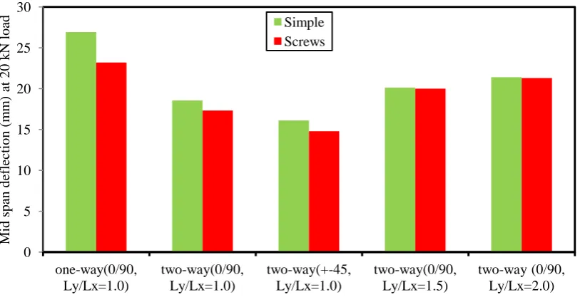
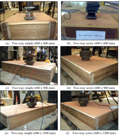
One-way and two-way GFRP sandwich slabs were tested under static point load. GFRP sandwich slab tests showed that the core to skin ratio and the total slab thickness have a big effect on the GFRP sandwich slab load capacity. Slabs with 18 mm thickness and with a 3 mm skin thickness showed double load capacity compared to 15 mm slab thickness with a 1.8 mm skin thickness. In addition, the support system has an effect on the slab behaviour and it represents an important aspect in the design. The two-way supported slab has approximately double loading capacity compared to the one-way supported slab. Square slabs with ±45o fibre orientation have a lower deformation and higher stiffness than 0o/90o orientation two-way square slabs. The effect of screw boundary restraint has a small influence on the behaviour of GFRP sandwich slabs. The effect of the slab width to length ratio is small at service load levels while it has more impact on the ultimate failure load level. The ultimate failure load decreases as the slab width to length ratio is increasing.
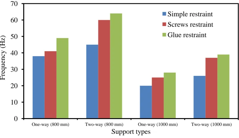
Moreover, glue restraints have a larger frequency than screw restraint slabs. The 0o/90o and ±45o skin fibre orientations were also studied. GFRP one-way sandwich slabs with ±45o fibre orientation had a lower frequency than slabs with 0o/90o fibre orientation, while, the GFRP two-way sandwich slab with ±45o fibre orientation had a higher frequency than slabs with 0o/90o fibre orientation.
Non-linear FEA revealed that the material models for the skin and phenolic core give an acceptable behaviour. The comparison of the FEA results was done with different experimental tests for the slabs and beams. The FEA model using the CRUSHABLE FOAM model and Hashin model gave a good prediction for the GFRP sandwich structure’s behaviour. The core part did not reach the hardening behaviour when the structure failed due to core shear and top skin compression. The same FEA model was used to predict the free vibration of the GFRP sandwich slabs. The FEA model developed in this work provided a good prediction of the free vibration behaviour of GFRP sandwich beams and slabs. This model can be used for design optimisation with confidence.
Multi-objective optimisation revealed that slab thickness is affected by the slab span. The required slab skin thickness and core thickness have an approximately linear relationship with the slab span length. The slab and beam designs are controlled by mid-span deflection limits. The strength constraints showed no contribution to the design optimisation. The design showed that the optimum core to skin thickness ratio of the beam is 11.0. The glue laminated beam optimisation indicated that the single sandwich beam has an optimum depth design less than the glue laminated beam. The depth of the glue laminated beam increases with the increase of sandwich layers.
Certification of Dissertation
I certify that the ideas, experimental work, results, analysis, and conclusions reported in this dissertation are entirely my own effort, except where otherwise acknowledge. I also certify that the work is original and has not been previously submitted for any award, except where otherwise acknowledged.
………. / /2012
Signature of Candidature Ziad Khalaf Awad
Date
ENDORSEMENT
………. / /2012
Signature of Supervisor/s
Date
………. / /2012
Signature of Supervisor/s
Acknowledgements
My thanks and appreciations go to Assoc. Prof. Thiru Aravinthan, my principal supervisor, for his guidance, encouragement, persistence, patience and expert advice. Interaction with him has inspired my love of research and has allowed me to seek new and exciting challenges. I will always remember the time we spent on research and publications. I wish to express my sincere gratitude to my associated supervisor Dr. Yan Zhuge and my external adviser Dr. Luis Felipe Gonzalez Toro from Queensland University of Technology (QUT), for guiding this project and making me realize the importance of perfection and quality. In addition, my great thanks for Prof. Frank Bullen for his expert advice and valuable input to my research.
I also would like to thank Assoc. Prof. Talal Yusaf for his support. My thanks also go to Assoc. Prof. Karu Karunasena for his support at initial stage of the research. Thanks are also in order to Dr. Allan Manalo, Dr. Jayantha Epaarachchi, Dr. Belal Yusaf, Wayne Crowell, Mohan Trada, my colleagues, and all the technicians in the USQ labs and offices. I would also like to acknowledge the support of the Faculty of Engineering and Surveying and the Center of Excellence in Engineering Fibre Composites. Also, I thank FoES Associated Dean (Research) Assoc. Prof. Armando Apan and his assistant Juanita Ryan for their support. My acknowledgment to my sponsor Iraqi Government, and special thanks to the Iraqi Cultural Attaché office (Canberra) for all the supports during the period of the study. Finally, my thanks go to Ernest Dunwoody, who helps me in editing the thesis.
Associated publications
1Journals
Awad, ZK, Aravinthan, T, Zhuge, Y & Gonzalez, F 2012, 'A review of optimization
techniques used in the design of fibre composite structures for civil engineering applications', Materials & Design, vol. 33, no. 1, pp. 534-44.
Awad, ZK, Aravinthan, T, & Manalo, A 2012, 'Geometry effect on the behaviour of
single and glue-laminated GFRP composite sandwich beams loaded in four-point bending ', Materials & Design, vol. 39, pp. 93-103.
Awad, ZK, Gonzalez, F & Aravinthan, T 2010, 'Advanced robust design
optimization of FRP sandwich floor panels', IOP Conference Series: Materials Science and Engineering, vol. 10, no. 1, pp. 1-9.
Awad, ZK, Aravinthan, T, & Zhuge, Y 2012, 'Experimental and numerical analysis
of an innovative GFRP sandwich floor panel under point load ', Engineering Structures, vol. 41, pp. 126-35.
Awad ZK, Aravinthan, T, & Zhuge, Y, 'Investigation of the free vibration behaviour
of an innovative GFRP sandwich floor panel ', Construction & Building Materials,
(under review).
Refereed conference proceedings
Awad, ZK, Aravinthan, T & Zhuge, Y 2009, 'Finite element analysis of fibre
composite sandwich panel', paper presented to Southern Engineering Conference: Infrastructure Investment for a New Economy, Springfield, Queensland, Australia.
Awad, ZK, Aravinthan, T & Zhuge, Y 2010, 'Cost optimum design of structural
fibre composite sandwich panel for flooring applications', paper presented to 5th International Conference on FRP Composites in Civil Engineering (CICE 2010), Beijing, China.
Awad, ZK, Aravinthan, T, Zhuge, Y & Gonzalez, F 2010, 'Multi-objective design
optimization of an innovative fibre composite sandwich panel for civil engineering applications', paper presented to 21st Australasian Conference on the Mechanics of Structures and Materials: Incorporating Sustainable Practice in Mechanics of Structures and Materials (ACMSM21), Melbourne.
Awad, ZK, Aravinthan, T, Zhuge, Y & Gonzalez, F 2010, 'Investigation of
frequency characteristics of GFRP/phenolic sandwich beams', paper presented to Southern Region Engineering Conference (SREC2010), Toowoomba, QLD 4350, Australia.
Awad, ZK, Aravinthan, T, Zhuge, Y & Gonzalez, F 2012, 'Multi-objective design
optimization of GFRP sandwich Beam', Abstract submitted to ACMSM22 conference, Sydney.
Table of Content
List of Figures
xiiList of Tables
xviiiNotations
xxChapter 1
Introduction
1.1 General 1
1.2 Background 2
1.2.1 FRP composite elements 3
1.2.2 FRP structure design optimisation 4
1.3 Novel GFRP sandwich panel 5
1.4 Objectives 7
1.5 Scope of the thesis 7
1.6 Thesis outline 8
1.7 Summary 9
Chapter 2
Design of FRP composite civil engineering
structures: a review
2.1 Introduction 10
2.2 Challenges in the design of fibre composite structures 12 2.3 Experimental investigation of fibre composite structures 13
2.3.1 Fibre composite beam 13
2.3.2 Fibre composite deck 16
2.4 Analytical methods of fibre composite structure 19
2.5 Optimisation methods in fibre composite structural design 22
2.5.1 Design Sensitivity Analysis (DSA) 22
2.5.2 Genetic Algorithm (GA) 23
2.5.3 Simulating Annealing method (SA) 25
2.5.4 Reliability Based Design Optimisation (RBDO) 25
2.5.5 Particle Swarm Optimisation Algorithm (PSOA) 26
2.5.6 Ant Colony Optimisation (ACO) 27
2.5.7 Multi-objective Robust Design Optimisation (MRDO) 28
2.5.8 Other optimisation methods 29
2.5.9 A comparison of optimisation methods 31
2.6 Proposed optimisation approach for civil infrastructures 34
2.7 Chapter conclusions 36
Chapter 3
Behaviour of single and glue laminated
GFRP sandwich beams
3.1 Introduction 37
3.2 Materials and specimens 39
3.2.1 GFRP skin and modified phenolic core 39
3.2.3 Samples preparation 40
3.3 Experimental procedure 42
3.4 Experimental results 42
3.4.1 Load-displacement behaviour 42
3.4.2 Failure mechanism 47
3.5 Discussion 54
3.5.1 Effect of shear span to depth ratio on shear capacity 54 3.5.2 Effect of shear span to depth on flexural behaviour 56 3.5.3 Effect of shear span to depth ratio on failure behaviour 57
3.5.4 Comparison with theoretical predictions 58
3.6 Failure map of GFRP sandwich beams 64
3.7 Chapter conclusions 66
Chapter 4
Behaviour of GFRP sandwich slabs
4.1 Introduction 67
4.2 Samples preparation 68
4.3 Experimental procedure 70
4.4 Experimental results 72
4.4.1 One-way GFRP sandwich slab 72
4.4.2 Two-way GFRP sandwich slab 77
4.5 Discussion 83
4.5.1 Comparison of slabs load-deflection behaviour 83
4.5.2 Effect of fibre orientations 86
4.5.3 Effect of restraint conditions 88
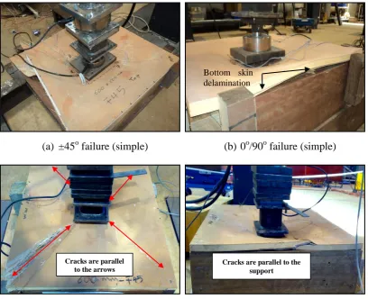
4.5.4 Mode of failure 90
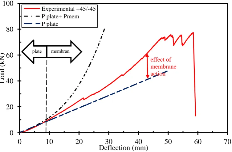
4.5.5 Membrane action 94
4.6 Chapter conclusions 96
Chapter 5
Free vibration behaviour of GFRP sandwich
slabs
5.1 Introduction 97
5.2 Experimental procedure 99
5.2.1 Samples preparations 99
5.2.2 Test setup 103
5.3 Experimental results and discussion 104
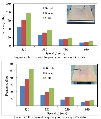
5.3.1 Effect of span length 104
5.3.2 Effect of support restraint 107
5.3.3 Effect of one-way and two-way spanning supports 109
5.3.4 Effect of fibre orientations 111
5.3.5 Comparison with theoretical prediction 113
5.4 Chapter conclusions 116
Chapter 6
FE simulation and modelling verifications
6.1 Introduction 118
6.2 Finite Element formulation 119
6.2.2 Contact Interaction 122
6.2.3 Core-skin interaction 125
6.2.4 Extended Finite Element Method 126
6.3 Material constitutive models 127
6.3.1 Core constitutive model 127
6.3.2 GFRP skin model 129
6.3.3 User subroutine UMAT 132
6.4 Validation of the FEA models 134
6.4.1 Modified phenolic core 135
6.4.2 GFRP skin 137
6.4.3 Skin - core interaction 137
6.4.4 UMAT subroutine verification 139
6.4.5 Mesh size sensitivity 140
6.5 GFRP sandwich beam simulation 141
6.5.1 Single sandwich beam 141
6.5.2 Glue laminated sandwich beam 147
6.6 GFRP sandwich slab simulation 152
6.6.1 One-way slab 152
6.6.2 Two-way GFRP sandwich slab 156
6.7 Free vibration simulation of slabs 162
6.8 Chapter conclusions 167
Chapter 7
Optimum design of GFRP sandwich slabs
and beams
7.1 Introduction 169
7.2 Slab design criteria 170
7.2.1 Service load 171
7.2.2 Deflection 171
7.2.3 Safety factor 171
7.2.4 Free vibration 173
7.3 Genetic Algorithm optimisation method 173
7.3.1 Multi-objective genetic algorithm (MOGA) 176
7.3.2 Adaptive range multi-objective genetic algorithm 178
7.4 Interaction between FEA and optimisation method 180
7.5 Multi-objective design optimisation of GFRP sandwich slabs
182
7.5.1 Serviceability and ultimate design constraints 184
7.5.2 One-way and two-way slabs design 188
7.5.2.1 Fibre orientations 188
7.5.2.2 Cost and mass objectives 190
7.5.2.3 Frequency design 196
7.6 Multi-objective design optimisation of GFRP sandwich beam
199
7.6.1 Problem description 200
7.6.2 Single layer sandwich beam 201
7.6.3 Glue laminated sandwich beam design 205
7.7 Slab - beam design 210
Chapter 8
Summary and conclusions
8.1 Summary 213
8.2 Main conclusions from this study 214
8.2.1 Behaviour of GFRP sandwich structures 214
8.2.2 FE simulation and modelling of GFRP sandwich structures
215
8.2.3 Design optimisation of GFRP sandwich structures 216
8.3 Recommendations for future work 217
References
219Appendix A
FRP composite materials mechanical
properties
A.1 Micromechanics of fibre composite A-1
A.1.1 Mass fraction A-1
A.1.2 Volume fraction A-2
A.1.3 Density A-2
A.1.4 Mechanical properties A-2
A.2 GFRP sandwich panel components testing A-3
A.2.1 GFRP composite skin A-3
A.2.2 Modified phenolic core A-5
A.2.3 Skin-core interaction A-9
A.3 GFRP skin mechanical properties A-11
A.3.1 Ply properties A-11
A.3.2 GFRP skin stiffness A-13
References A-14
Appendix B
Free vibration behaviour of GFRP sandwich
beams
B.1 Introduction B-1
B.2 Experimental program B-1
B.2.1 Test specimens B-1
B.2.2 Test setup B-2
B.3 Experimental tests and discussion B-2
B.4 FEA simulation B-6
References B-8
Appendix C
Source code: UMAT subroutine
Source code: UMAT subroutine C-1
Appendix D
Design of slab- beam structure
D.1 Introduction D-1
D.3 Slab-beam model analysis D-4
D.3.1 Cost and mass D-4
D.3.2 Deflection behaviour D-5
D.3.3 Load capacity D-6
D.3.4 Frequency D-8
List of Figures
Chapter 1
Introduction
Figure Figure title Page
1.1 FRP civil structural applications. 2
1.2 FRP composite elements. 4
1.3 Novel GFRP sandwich panel. 6
1.4 Structural applications of the GFRP sandwich panel. 6
Chapter 2
Design of FRP composite civil engineering
structures: a review
Figure Figure title Page
2.1 Material specific characteristics. 11
2.2 FRP girders for bridge applications in Australia. 14
2.3 FRP composite girders. 15
2.4 Novel GFRP sandwich beam applications. 15
2.5 FRP deck sections (Gan et al. 1999). 17
2.6 Assembly bridge deck (Kumar et al. 2004). 17
2.7 Bridge deck (Roy et al. 2005). 17
2.8 Bridge deck (Van-Erp et al. 2005). 17
2.9 FRP deck units. 18
2.10 Novel GFRP slab test. 19
2.11 Composite laminate orientations. 24
2.12 Sandwich bridge deck (He & Aref 2003). 24
2.13 FRP deck (Kim et al. 2005). 24
2.14 FRP deck (Kim et al. 2009). 24
2.15 Panel details (Kovács et al. 2004). 27
2.16 Five layers beam. 30
2.17 FRP poles. 30
2.18 Fibre distributions. 30
2.19 Proposed design optimisation methodology of FRP structures. 35
Chapter 3
Behaviour of single and glue laminated
GFRP sandwich beams
Figure Figure title Page
3.1 GFRP sandwich panel. 40
3.2 Samples of sandwich beam. 41
3.3 Schematic illustration of flexural test. 42
3.4 Load-displacement curves for single sandwich beams (GB3). 44 3.5 Load-displacement curves of two layer GFRP sandwich
beams (GB4).
45
3.6 Load-displacement curves of three layer GFRP sandwich beams (GB6).
45
beams (GB5).
3.8 Load-displacement curves of five layer GFRP sandwich beams (GB7).
46
3.9 Failure modes of single sandwich beams with different shear span to depth ratios (a/d).
50
3.10 Strain-load curves for single layer sandwich beams (GB3). 51 3.11 Failure modes of two layer glue laminated sandwich beam
with different shear span to depth ratios (a/d).
51
3.12 Failure modes of three layer glue laminated sandwich beam with different shear span to depth ratios (a/d).
52
3.13 Failure modes of four layer glue laminated sandwich beams with different shear span to depth ratios (a/d).
53
3.14 Failure modes of five layer glue laminated sandwich beams with different shear span to depth ratios (a/d).
53
3.15 Normalised shear strength versus shear span to depth ratios. 55 3.16 Schematic diagrams for the shear failure in the beams. 56 3.17 Normalised bending strength versus shear span to depth ratio. 57 3.18 Experimental and predicted failure loads of GFRP sandwich
beams.
61
3.19 Experimental and predicted failure loads of two and three layer GFRP sandwich beams.
61
3.20 Apparent stiffness modulus versus the a/d ratio for GFRP sandwich beams.
62
3.21 Failure-map of GFRP sandwich beams (x-axis in logarithm scale).
65
Chapter 4
Behaviour of GFRP sandwich slabs
Figure Figure title Page
4.1 Fibre orientation of the GFRP sandwich slabs. 68
4.2 Timber supports for slab tests. 69
4.3 GFRP sandwich slabs cross sections. 70
4.4 Strain gauge positions for slabs P1, P2, P3, P8, P9, P10, and P11.
71
4.5 Strain gauge positions for slabs P4 and P5. 71
4.6 Strain gauge positions for slabs P6 and P7. 71
4.7 Slab setup. 72
4.8 Load-deflection curves of single span sandwich slabs (15 mm and 18 mm thicknesses).
74
4.9 Central deflection and edge deflection of 15 mm thickness one-way slab.
74
4.10 Load-strain of simple restraint slab (15 mm thickness). 75 4.11 Load-strain of simple restraint slab (18 mm thickness). 75 4.12 Comparison between strain at centre and edge of one-way slab 76 4.13 Load-strain of screw restraint slab (18 mm thickness) 76 4.14 Load - deflection for 600 x 600 mm slab 0o/90o fibre
orientation.
78
4.15 Load - deflection for 600 x 600 mm slab ±45o fibre orientation.
4.16 Load-deflection curves for 600 x 900 mm slab. 79
4.17 Load-deflection curves for 600 x 1200 mm slab. 79
4.18 Load-strain for 600 x 600 simple restraint slabs. 80
4.19 Load-strain curves for simple restraint GFRP slabs. 81
4.20 Load-strain curves for screw restraint two-way slabs. 82 4.21 Load-deflection curves for two-way and one-way slabs. 84
4.22 Mid-span deflection of slabs at load equal to 20 kN. 86
4.23 Stiffness of simple and screw restraints slabs. 86
4.24 Load-deflection for two-way 600 x 600 mm simple restraint slabs.
87
4.25 Load-deflection for two-way 600 x 600 mm simple restraint slabs.
87
4.26 Deformation shapes of simple restraint slabs. 88
4.27 Deformation shapes of 0o/90o one-way slabs (600 x 600 mm). 89 4.28 Deformation shapes of simple and screw restraints two-way
slabs.
89
4.29 Failure mode of one-way slab. 91
4.30 Failure mode of one-way 18 mm thickness slab. 91
4.31 Failure mode of 600 x 600 mm two-way slab. 92
4.32 Failure mode of 600 x 900 mm two-way slab. 93
4.33 Failure mode of simple restraint 600 x 1200 mm two-way slab 93 4.34 Schematic diagram for the possible failure in two-way slab. 94
4.35 Effect of plate and membrane action. 95
Chapter 5
Free vibration behaviour of GFRP sandwich
slabs
Figure Figure title Page
5.1 Timber support types. 100
5.2 Boundary restraint types. 100
5.3 Experimental setup. 101
5.4 Accelerometer position. 103
5.5 First natural frequency for one-way (S1) slabs. 105
5.6 First natural frequency for two-way (S2) slabs. 105
5.7 First natural frequencies for continuous (S3 and S4) slabs. 105 5.8 Frequency-span relationship of the slab with span centre to
centre.
108
5.9 Schematic drawings for the effective span. 108
5.10 Frequency-span relationship of the slab with modified span. 109
5.11 Comparison between one-way and two-way slabs. 110
5.12 One-way support (S1) slabs. 112
5.13 Two-way support (S2) slabs. 112
5.14 Prediction of one-way GFRP slab frequency. 115
5.15 Prediction of two-way GFRP slab frequency. 116
Chapter 6
FE simulation and modelling verifications
Figure Figure title Page
6.2 Fibre composite material in 3D model. 122
6.3 Master and slave surfaces. 123
6.4 Interaction between nodes in master and slave surfaces. 123 6.5 Tied interface between two regions (Zienkiewicz & Taylor
2005).
125
6.6 Phenolic core modelling. 129
6.7 GFRP skin model. 132
6.8 UMAT subroutine flow chart. 134
6.9 Core tension and compression simulation. 136
6.10 GFRP skin tensile FEA simulation. 137
6.11 Skin-core interaction. 138
6.12 Comparison between shell and 3D continuum solid element (UMAT) in the simulation of GFRP skin.
139
6.13 GB3-400 mm GFRP sandwich beam. 141
6.14 3D FEA model of four point bending sandwich beam. 142
6.15 Load-displacement for single sandwich beam. 143
6.16 Load-strain for single sandwich beam. 144
6.17 Stresses distribution in the mid span gross section. 144
6.18 Comparison of single sandwich failure prediction. 145
6.19 Load-displacement for glue laminated sandwich beam. 148
6.20 Vertical stress in the core under loading point and support. 149
6.21 Comparison of glue laminated failure prediction. 150
6.22 Mid span cross section beams axial stress distribution. 151
6.23 3D FEA model for the one-way GFRP sandwich slab. 152
6.24 Load-deflection curve of single span 15 mm slab. 154
6.25 Load-deflection curve of single span 18 mm slab. 154
6.26 Finite element and experimental load-strain results for the 15 mm slab thickness.
155
6.27 Core crack under point load. 155
6.28 Top skin failure. 156
6.29 Von-Mises stress distribution. 156
6.30 3D FEA model of two-way GFRP sandwich slab. 157
6.31 Load-deflection curve for 0o/90o two-way slab restrained by screws.
158
6.32 Load-deflection curve for ±45o two-way slab restrained by screws.
158
6.33 Load-deflection curves for rectangular two-way slab with simple restraint.
159
6.34 Core crack under point load. 160
6.35 Von-Mises stress distribution of 600 x 600 mm two-way slabs.
160
6.36 Von-Mises stress distribution in rectangular slab. 160
6.37 Yield pattern. 161
6.38 Experimental and numerical first natural frequency of S1 support.
163
6.39 Experimental and numerical first natural frequency of S2 support.
Chapter 7
Optimum design of GFRP sandwich slabs
and beams
Figure Figure title Page
7.1 GA flow chart. 175
7.2 The bit-string crossover of parents a, and b to form off-strings c and d.
175
7.3 Mutation of string chromosomes. 175
7.4 Pareto optimisation. 177
7.5 Multi criteria decision making (Avila et al. 2006). 178
7.6 Range adaptive. 179
7.7 ARMOGA regions. 180
7.8 Optimisation flow charts. 181
7.9 Schematic diagrams for slabs. 183
7.10 Cost and mass scatter chart for the service and ultimate load designs.
186
7.11 Design variables. 186
7.12 Comparison between stress design constraints. 187
7.13 Comparison between serviceability and ultimate load design slab behaviour.
188
7.14 Fibre orientation in the GFRP skin. 189
7.15 Optimum fibre orientations of square one-way slab. 189
7.16 Optimum fibre orientations of two-way slab. 190
7.17 Scatter chart for different spans design of one-way slab. 192 7.18 Scatter chart for different spans design of two-way slab. 192
7.19 Cost objective with span. 194
7.20 Mass objective with span. 194
7.21 Optimum core thickness. 195
7.22 Optimum skin thickness. 195
7.23 Load factor for the designed one-way slabs. 196
7.24 Slabs first natural frequency. 197
7.25 Core thicknesses with frequency for one-way and two-way slabs.
198
7.26 Skin thicknesses with frequency for one-way and two-way slabs.
199
7.27 Schematic diagram of beams supporting slab. 201
7.28 Schematic diagram of single sandwich beam. 201
7.29 Scatter chart of mass and cost of the sandwich beams (load = 8.2 kN/m).
203
7.30 Optimum core and skin thicknesses. 204
7.31 Optimum cost and mass core to skin ratios. 205
7.32 Optimum single sandwich beam depth. 205
7.33 Optimum depth of two sandwich layers GFRP sandwich beam.
206
7.34 Design constraints of the glue laminated GFRP sandwich beam (4800 mm, 6-layers).
207
7.35 Effect of the number of sandwich layers on the optimum beam depth (4800 mm span, and 17.5 kN/m load).
208
kN/m applied load.
7.37 Effect of GFRP sandwich layers on the beam section stress distribution.
209
7.38 GFRP sandwich beam depth with applied moment. 210
7.39 Slab-beam models. 211
Appendix A
FRP composite materials mechanical
properties
Figure Figure title Page
A.1 FRP skin configuration. A-3
A.2 GFRP skin samples. A-5
A.3 Stress-strain of the GFRP skin. A-5
A.4 Stress-strain of modified phenolic core. A-6
A.5 Experimental setup. A-7
A.6 Core shear specimens. A-7
A.7 Three point bending. A-8
A.8 Flexural samples. A-8
A.9 Load-Strain of core flexural test. A-8
A.10 Sample dimensions. A-10
A.11 Sample of skin core interaction test. A-10
A.12 Stress -strain of GFRP skin core interaction. A-10
A.13 Plies theoretical thicknesses. A-12
Appendix B
Free vibration behaviour of GFRP sandwich
beams
Figure Figure title Page
B.1 Experimental setup. B-2
B.2 Free vibration spectrum of simply supported (beam-1). B-3
B.3 Free vibration spectrum of cantilever beam (beam-2). B-3
B.4 Free vibration spectrum of fixed supported (beam-3). B-3
B.5 Frequency spectrum of GFRP glue laminated sandwich beam (beam-4).
B-4
B.6 Half power method for damping estimation. B-5
Appendix D
Design of slab- beam structure
Figure Figure title Page
D.1 Cost and mass of the slab-beam models D-4
D.2 3D FE for slab-beam model-C D-5
D.3 Deflections of the slab-beam models at service loading D-6
D.4 Load-deflection of four models at centre D-7
D.5 Failure of different slab-beam models D-8
List of Tables
Chapter 2
Design of FRP composite civil engineering
structures: a review
Table Table title Page
2.1 Comparison of the optimisation methods. 33
Chapter 3
Behaviour of single and glue laminated
GFRP sandwich beams
Table Table title Page
3.1 Properties of GFRP sandwich panel. 40
3.2 GFRP sandwich beam specimen details. 41
3.3 GFRP sandwich beams experimental results. 47
3.4 Failure load of GFRP sandwich beams. 63
Chapter 4
Behaviour of GFRP sandwich slabs
Table Table title Page
4.1 GFRP sandwich slab samples. 69
4.2 Experimental results summary. 83
Chapter 5
Free vibration behaviour of GFRP sandwich
slabs
Table Table title Page
5.1 GFRP sandwich slab samples. 102
5.2 Natural frequency of one-way (S1) slabs. 106
5.3 Natural frequency of two-way (S2) slabs. 106
5.4 Natural frequency of continuous (S3 and S4) slabs. 106
5.5 Natural frequency of 600 x 600 mm slabs. 111
Chapter 6
FE simulation and modelling verifications
Table Table title Page
6.1 Materials mechanical properties. 135
6.2 Modified phenolic core hardening. 136
6.3 Experimental and FEA prediction results of GFRP sandwich beams
146
6.4 FEA and experimental results for GFRP sandwich slabs. 161
6.5 FEA free vibration simulation results. 164
6.6 First mode shape of single span slabs of 0o/90o fibre orientations
165
6.7 First mode shape of continuous span slabs of 0o/90o fibre orientations
Chapter 7
Optimum design of GFRP sandwich slabs
and beams
Table Table title Page
7.1 Objectives and constraints 182
7.2 Fibre orientation design of the GFRP skin 190
7.3 Cost and mass optimisation results of one-way slab 193
7.4 Cost and mass optimisation results of two-way slab 193
7.5 Beam loading values. 201
7.6 GFRP sandwich beam cross section optimisation results. 203
Appendix A
FRP composite materials mechanical
properties
Table Table title Page
A.1 Skin tensile properties A-4
A.2 Modified phenolic core mechanical properties A-8
A.3 Manufacturer mechanical properties A-12
A.4 Plies mechanical properties A-12
A.5 GFRP skin stiffness A-13
Appendix B
Free vibration behaviour of GFRP sandwich
beams
Table Table title Page
B.1 GFRP sandwich beam samples B-2
B.2 Experimental and analytical results B-4
B.3 Damping ratios B-5
B.4 Free vibration results of a simply supported GFRP sandwich beam
B-6
B.5 Glue laminated sandwich beam natural frequency B-7
Appendix D
Design of slab- beam structure
Table Table title Page
Notations
A Area
a Shear span
an Boundary conditions parameters
Momentum
b Width
Strength of attraction coefficient
c Core thickness
C Cost
c1 Aspect ratio constant
Particle position factor
Cij Stiffness coefficient
D Rigidity
d Depth
dc Distance from the centre of the core to the neutral axis df, dm, and ds Damage factors for the composite
ds Distance from the centre of the skin to the neutral axis
E Elastic modulus
Ea Apparent stiffness modulus
Ecore Core elastic modulus
El Longitudinal elastic modulus
EI Equivalent bending stiffness
Eskin Skin elastic modulus
Et Transverse elastic modulus
f Frequency (hz)
favg Average fitness value
Fibre failure index in compression
Fibre failure index in tension
Inter-laminar compression failure
Inter-laminar tension failure
Matrix failure index in compression
Matrix failure index in tension
F.S Factor of safety
Fs Shear flexibility
fv Fitness value
Fitness value number
G Shear modulus
Gf Fibre shear modulus
Gm Matrix shear modulus
g1, g2, ….., gn Constraints
g Lagrange multiplayer
h Layer thickness
H Flexibility matrix
I Moment of inertia
i Iteration number
j Number of design constraints
K Stiffness
Number of the objective functions
L Span length
l Load span
Lx Longitudinal span length
Ly Transverse span length
Total length of the string
m Schema number
M Mass
Mb Bending moment
Mf Fibre mass Fraction
Mm Matrix mass Fraction
Damage operator
N Number of sandwich layers
n Constraints number
O(H) Order of Schema
P Point load
Probability
PG Shear capacity of glue laminated beam
Ps1, Ps2and Ps3 Shear load capacity
pcand pm Probabilities of crossover and mutation respectively
Q Transverse force
q Randomly generated number
qo Constant parameter
Qt First moment of area
r Core to thickness ratio
R Scalar damage variable
Optimum solution
Slab dimensions aspect ratio
RE Exterior radius of normalised tolerance
t Skin thickness
tf Fibre thickness
tm Matrix thickness
T Rotation matrix
The generation number
ult Subscript means ultimate
v Velocity
V Shear force
Vf Fibre volume fraction
Vm Mass volume fraction
W Distributed load
Feasible solution
Circular frequency (rad/s)
x Variable
Particle position
xs Position of slave surface
xm Position of master surface
x, y, z Global coordinates
XTand Xc Fibre strength in tension and compression
YTand Yc Matrix strength in tension and compression
ZTand Zc Normal strength of the composite layers αr and fli Control parameters
Parameter
The normal distribution
Standard deviation
The pheromone
βi Safety - index
δ Deflection
δ(H) length of Schema H
ε Strain
ζ Error
η Robust index
θ Fibre orientation
λ Lagrange multiplier
ξ Damping ratio
ρ Density
ζ Stress
ζf Skin stress
ζult Ultimate strength
η Shear stress
υ Poisson’s ratio
υf Fibre Poisson’s ratio
υm Matrix Poisson’s ratio
ψ Real response
Chapter 1
Introduction
1.1 General
There is a growing concern with the worldwide deterioration of traditional materials such as concrete, steel, and timber. Recently, attention has shifted to the use of fibre reinforced polymers (FRP) as alternative materials. Their light weight and high strength to weight ratio can produce a lighter structure with an increase the live load capacity. Furthermore, the resistance of FRP materials to corrosion means that they can be used to replace steel and reinforced concrete in situations when they would be exposed to corrosion. Generally, traditional materials like concrete, steel, and timber are cheaper than the FRP materials. Although there are overall benefits of using FRP materials, they are not commonly used in the civil engineering applications because of their higher initial cost than traditional materials. Furthermore, new FRP composite materials are being developed using different types of components. For these reasons, it is desirable to investigate and understand the existing FRP composites behaviour when it is used in civil engineering applications. This is compounded by the lack of standard design codes and specifications to guide their use in civil engineering applications.
Chapter 1 Introduction
(a) FRP bridge. (b) Floating walkway part.
[image:30.595.74.477.68.378.2](c) Pedestrian bridge deck. (d) Railway sleeper.
Figure 1.1FRP civil structural applications.
1.2 Background
Chapter 1 Introduction
Achieving the optimum use of materials needs a powerful and reliable numerical design tools to satisfy the FRP design parameters. This includes the use of complex geometric forms, multiple layers, and different materials. Investigators have spent a lot of attention in developing FRP design tools using different experimental tests, optimisation methods and analysis methods. The following sections of this chapter introduce the different FRP composite elements and the design of FRP structure.
1.2.1 FRP composite elements
Composite materials have different properties, and this allows different configurations to be made to meet different needs (Hassani & Hinton 1999). Glass fibre reinforced polymer (GFRP) is well known today in commercial markets and represents the most versatile industrial material. It has benefits of high-tensile strength, fire resistance, chemical resistance, hardness, moisture resistance (Frederick et al. 2001; Knox 1982), and relatively low cost compared to other composite products (Lavoie 1997).
However, it also has some disadvantages compared to traditional materials. These include its relatively low modulus of elasticity and its high cost. Different forms of GFRP composites are used for specific civil engineering applications such as; pultrusion, plates, and sandwich panel, as shown in Figure 1.2.
Chapter 1 Introduction
(a) Pultruded sections. (b) Panel and plate.
Figure 1.2 FRP composite elements.
1.2.2 FRP structure design optimisation
Composite materials have been developed to be used in numerous civil engineering applications during the last two decades. The laboratory tests were developed to identify design parameters and to document the behaviour of the FRP structures (Hadcock 1982). Experimental investigation and analysis were also conducted on FRP composite structures to understand their behaviour. This provided reliable information for the designers. Designing FRP composites structure requires considering serviceability requirements, design strength criteria, high temperature effects, water effects, durability and manufacturing complexity. There are no standard codes that specify or cover the full range of sections of composite members, including available sections properties and allowable strength (Cripps 2002). Most of the available FRP composite structure designs are conservative due to the limitation in the design standards and full understanding of the FRP materials behaviour. The existing FRP composite structure designs depend on different specifications. These specifications mainly rely on a combination of understanding the behaviour of FRP structures, experimental results, and the recommendations of the available codes and design guides (Quinn 1999).
Chapter 1 Introduction
structures have been developed during the last few decades and therefore, the
conjunction of them is more recent”.
Finite Element Analysis (FEA) method and optimisation methods were used in the design of FRP composite structures (Miravete 1996). The FEA method is able to deal with the complicated characteristics of the FRP materials such as their geometry, material behaviour, and multi-layer structure. Verification of the FE modelling with the experimental behaviour is strongly recommended before it is used in design. Design optimisation is required for FRP civil engineering structures to achieve cost savings, mass minimization, maximizing bending stiffness, and to enhance the structure against dynamic loading. Optimisation techniques can be used to find the ideal values of the design variables, find the relationships between both variables and constraints, and to design the structure to meet multiple objectives. Additionally, consideration of the effect of free vibration in the design is very important to avoid any structural resonance such as in building floors, stadiums, and bridges.
1.3 Novel GFRP sandwich panel
A novel fibre composite sandwich panel with GFRP skins and a solid modified phenolic core was developed by an Australian manufacturer (Manalo et al. 2010d; Van-Erp 2010). The core density of the panel is 950 kg/m3 higher than usual. The overall density of the novel GFRP sandwich panel is 1100 kg/m3. This sandwich panel offers many benefits compared to conventional sandwich panels including a high strength to weight ratio, good thermal insulation, moisture resistance, and termite resistance. The new panel composition is contains approximately 15 kg of polymer per square meter, and 65 % of this polymer is plant based (Van-Erp 2010). It has a carbon foot print similar to timber. Furthermore, this panel offers the ability to cut, drilled, glued, and shaped on site. These features give this type of composite panel a wide range of applications in Australia for use as; slabs, glue laminated beams, bridge decks and girders, and railway sleepers. A typical panel is shown in Figure 1.3.
trussed-Chapter 1 Introduction
core structures have a high compressive strength but low capacity to hold mechanical connections. The novel GFRP sandwich panel has a high core density which provides good resistance to compression forces. Several studies were done to investigate the mechanical properties of this GFRP sandwich panels. The flexural and shear behaviour of the single and glue laminated sandwich beams have been investigated by Manalo et al. (2010b; 2010c; 2010d). A preliminary study on the behaviour a slab under point load and distributed load was done by Islam and Aravinthan (2010). These investigations found that the product is suitable for structural applications. They recommended that the static and dynamic behaviour of the novel GFRP sandwich panel needed more investigation. In addition, the design of the novel GFRP sandwich panel as a new structural element needs more investigations. A sample of this panel in use a floor panel and bridge deck applications is shown in Figure 1.4.
Figure 1.3 Novel GFRP sandwich panel.
(a) Floor panel. (b) Bridge deck using glue-laminated
panels.
Chapter 1 Introduction
1.4 Objectives
Past research focused on the optimum design of FRP structural elements for use in civil, mechanical, and aeronautical applications. Exploring the design of the novel GFRP composite sandwich beams and slabs is essential to provide information for the engineers. The focus of this study is to investigate the behaviour of the innovative sandwich structures, build a FEA model, and find the optimum design for the GFRP sandwich slabs and beams in civil engineering applications. Studying the optimum design of the civil engineering structures mainly considers several parameters such as loads, spans, strength, and deflection limit for serviceability.
The main objectives of the study as follows:
(a) Understanding the static behaviour of the GFRP single sandwich beam, glue laminated sandwich beam, and slabs.
(b) Investigate the free vibration behaviour of the GFRP sandwich beams and slabs.
(c) Develop a non-linear 3D FEA model with an appoperiate subroutine for the GFRP sandwich structure simulation.
(d) Multi-objectve design optimisation for the GFRP sandwich slabs and beams with cost and mass minmisation.
1.5 Scope of the thesis
The current research focuses on the novel GFRP composite sandwich panel as a new product in civil engineering structural beam and slabs applications. This work considers the following aspects:
Review of the design optimisation techniques used in the design of FRP composite civil engineering structures.
Finding the GFRP skin and core material mechanical properties.
Testing and evaluating of the static load behaviour of GFRP sandwich beams and slabs under point load.
Chapter 1 Introduction
Compare the FE simulation with the experimental tests for the beams and slabs in both static and free vibration behaviours.
Optimise the GFRP sandwich beams and slabs under the variation of span and load.
The scope of the thesis was developed to achieve the design methodology for the novel GFEP sandwich structures. Nevertheless, the accompanying intellectual patent of this GFRP sandwich panel would not allow the author to consider the microstructure and materials optimisation of this product. In addition, due to thesis limitation the following issues are beyond the scope of the study:
Experimental investigation of the combined slab-beam structure.
Investigate the long term behaviour of the GFRP sandwich structures.
Impact and fatigue effects on the GFRP sandwich structures.
1.6 Thesis outline
The study is focused on understanding the behaviour of the novel GFRP sandwich structure, numerical modelling and simulation, and optimising the design of potential GFRP sandwich structures. The thesis is divided into 8 chapters as follows:
Chapter 1 is the introduction and it gives a brief outline of the background to FRP, novel sandwich panel, and a structure of the dissertation.
Chapter 2 reviews the existing studies on the optimum design of GFRP civil engineering structures such as; beams, slabs, and bridge decks. In addition, the review of literature explores the design of the existing FRP composite structures and how they were designed using different methods.
Chapter 3 covers the experimental investigation of the single and glue laminated GFRP sandwich beams in four point bending test. The GFRP sandwich beam geometry variations were considered in the experimental analysis.
Chapter 1 Introduction
Chapter 5 concerns with the experimental investigation of the GFRP sandwich slabs in free vibration. The variations considered in the experimental analysis are geometry, support types, and boundary restraints.
Chapter 6 presents the finite element modelling and simulation of the GFRP sandwich beams and slabs under static and free vibration behaviour.
Chapter 7 covers the design criteria of the GFRP slabs and the optimum design under uniformly distributed and point loads. In addition, the design of the single and glue laminated GFRP sandwich beam under the transverse load from the slabs was presented.
Chapter 8 summarising the main findings of the thesis and makes recommendations for future work.
1.7 Summary
Chapter 2
Design of FRP composite civil
engineering structures: a review
2.1 Introduction
In the last 70 years since the Second World War, fibre reinforced polymers (FRP) have been used in many structural applications due to their excellent strength and weight characteristics and because they can be used in applications with complex shapes (Iyer & Sen 1991). These composite materials can be classified into two groups. First is filled material, which is any material whose properties are improved by adding fillers. The second type is reinforced composite material, which has long high strength fibres bound by resin (Vasiliev & Morozov 2001). The FRP composite material typically contains fibre mixed with some resin. Commonly used types of fibre are glass, carbon and aramid. Types of resin include epoxy, polyester, vinylester, and Phenolic resins (Bank 2006). They have many benefits such as weight saving (high strength to weight ratio), able to add to the old structures in the form of strengthening and repairing, low maintenance requirements, resistance to environment effects, and an ability to be formed into complex shapes. All these advantages encourage engineers to use these materials in numerous structural forms. (Cripps 2002).
Two parameters are used to measure the relative advantages of composite materials. The specific modulus represents the ratio of the elastic modulus (E) to the density (ρ). The specific strength represents the ratio of ultimate strength ( ult) to the material density (Kaw 1997).
Specific modulus= 2.1
Chapter 2 Design of FRP composite civil engineering structures: a review
Specifications of different materials are shown in Figure 2.1 (Gay et al. 2003). FRP materials have been used increasingly in the last two decades in civil engineering applications to construct large-scale fibre composite structures such as traffic and pedestrian bridges. Pedestrian bridges in rural areas are perhaps the best known application of the fibre composites, but there are limited design guidelines for these applications. Designers are likely to combine between the specification for pedestrian bridge crossings and specifications for highway bridge (Abro et al. 2007; Nayomon & Nobuhiko 2003). Most of the available fibre composite design structures depend on the coupon level experimental tests. The results from this test are adopted in the Finite Element Analysis (FEA) model to get the analysis results used for designing the real structure (Spearing et al. 1998). Manual prediction of the design variables during re-analysis is unlikely to produce an optimum design. The efficiency of the re-analysis process depends on the experience of the designers.
Figure 2.1 Material specific characteristics (Adopted from Gay et al. (2003)).
Chapter 2 Design of FRP composite civil engineering structures: a review
carry a load of 500 kg/m2 (Keller et al. 2007). Additionally, fibre composites have also been used to construct railway sleepers (Namura et al. 2005), floating walk-ways and piles (Van-Erp et al. 2006). Generally, the composite beam and slab elements support other brittle parts of the structure such as walls and finishing. Therefore, the allowable deflection limit under the service load is an important consideration in the design. The EUROCOMP design code recommends a deflection limit for the fibre composite structure under the serviceability conditions which is between span/150 to span/400 (Clarke 1996).
In the USA, attention has been focused on the use of fibre composites for non-corrosive and light weight bridge decking systems. Over 117 bridges have been built or rehabilitated up till 2008 using fibre composites (O'Connor 2008). In the absence of the beneficial design standards for fibre composite structures in civil engineering applications, the optimisation methods and Finite Element Analysis (FEA) represent the best way of getting an acceptable structural design solution. This chapter reviews the importance of the optimisation techniques and their application to the design of fibre composite structures of civil engineering purposes.
2.2 Challenges in the design of fibre composite
structures
Chapter 2 Design of FRP composite civil engineering structures: a review
process (Kim et al. 2011). Any design method for fibre composite structures should consider the fibre plies design level and the overall geometry level of the structure. Optimisation methods offer the advantage of solving the geometry and materials design issues simultaneously.
2.3 Experimental investigation of fibre composite
structures
The experimental investigation is regarded as an important assessment for the design of composite structures. This section presents the available experimental studies in the civil engineering application of fibre composite beams and decks.
2.3.1 Fibre composite beam
Fibre composite girders have been used by civil engineers to replace traditional wood girder in old bridges. There are about 27,000 timber bridges in Australia. Most of them are 50 years old and have degraded due to age and environmental conditions (Crews et al. 2004). The Queensland Department of Transport and Main Roads recommended the replacement of these degraded bridge girders by new girders with the same stiffness. There are a few design requirements by the Queensland Department of Transport and Main Roads related to the stiffness of the new girder. The CEEFC has participated in the development of a new hybrid composite girder. The novel GFRP sandwich panel was used in the development of the hybrid girder. The cross sections and dimensions of the girder beam are shown in Figure 2.2(a) (Aravinthan 2009).
Chapter 2 Design of FRP composite civil engineering structures: a review
design requirement for environmental impact, long-term durability, load variation, cost, and dynamic response.
(a) Beam girder using sandwich panels. (b) Beam girder using pultruded
sections.
Figure 2.2 FRP girders for bridge applications in Australia (Aravinthan 2008, Aravinthan 2009).
Chapter 2 Design of FRP composite civil engineering structures: a review
(a) FRP double web girder. (b) Girder using pultruded sections and sandwich panels.
Figure 2.3 FRP composite girders.
The novel GFRP sandwich beam has been studied by Manalo et al. (2010b; 2010c; 2010d) for possible application as a railway sleeper. These investigations were carried out on the fixed beam span, and were focused on using edgewise and flatwise concepts as shown in Figure 2.4(a). However, these studies did not investigate the beam behaviour under a combined action of shear and flexural loading. The recommendation was made that the novel beam required an investigation for effect of combined shear and flexure in different shear-span to depth ratios (Manalo 2011). The application of the novel glue-laminated GFRP sandwich beam was extended for full-scale railway sleepers as shown in Figure 2.4(b) (Manalo 2011).
(a) Sandwich beam. (b) Full scale railway sleeper cross
sections.
Chapter 2 Design of FRP composite civil engineering structures: a review
2.3.2 Fibre composite deck
Many countries have started to use fibre composite materials for bridge decks instead of conventional concrete, steel, and wood materials. The conventional decks showed degradation under the effects of cyclic loading and the environmental action (O'Connor 2008). Gan et al. (1999) evaluated available cross sections for the fibre composite deck. The research considered seven applicable composite deck sections as shown in Figure 2.5. The optimum section was found to be a triangular. This type of section enhanced both the global and local stiffness and improved buckling resistance. Jeong et al. (2007) on the other hand, tried to find the safety factor for fibre composite pultruded deck materials by static and fatigue tests to provide a comprehensive data for designers and engineers. The experimental test was conducted by applying a load equivalent to DB-24 truckload which provided a maximum load of 117.6 kN. The test showed that ultimate failure load was 431.2 kN with a service deflection of 1.74 mm less than span/800 and the strain is 13% of the ultimate strain. Kumar et al. (2004) conducted an experimental study to investigate the behaviour of a composite bridge deck with dimensions of 9.144 m x 2.743 m. The deck was made of square pultruded glass and carbon fibre tubes with dimensions of 76.2 mm x 76.2 mm x 3 mm as shown in Figure 2.6. The first version of this deck had 8-pultrusion layers. The experimental test indicated that the 8-pultrusion layers deck was over designed. The final decision was made that the deck comprised of 7-pultrusion layers in an I-beam configuration was able to carry the external load. The load of which the deck failed was about 155 kN, which was four times the design load of H-20 (35.587 kN).
Chapter 2 Design of FRP composite civil engineering structures: a review
(a) (b)
(c) (d)
(e) (f)
(g)
Figure 2.5 FRP deck sections (Gan et al. 1999).
Figure 2.6 Assembly bridge deck (Kumar et al. 2004).
Figure 2.7 Bridge deck (Roy et al. 2005).
Chapter 2 Design of FRP composite civil engineering structures: a review
An experimental investigation was conducted by Zi et al. (2008) on the effect of foam fill on the behaviour of rectangular GFRP bridge deck section as shown in Figure 2.9(a). It was found that using low modulus polyurethane foam enhances the structural behaviour in the transverse direction. Design and experimental investigations were conducted on the development of ASSET FRP bridge deck unit as shown in Figure 2.9(b) (Luke et al. 2002). This deck was used in the construction of West Mill Bridge in the UK. A similar deck system was used for the Friedberg Bridge in Germany (Knippers & Gabler 2006). It was tested experimentally for the material’s mechanical properties and composite action with steel girder. They concluded that further investigation was required to cover the shortage of comprehensive design guidelines.
(a) Rectangular pultruded FRP unit (b) Triangular pultruded FRP unit
Figure 2.9 FRP deck units.
The novel GFRP sandwich panel was used in the construction of the floors and bridge decks as described in Chapter 1, and shown in Figure 1.4. Islam and Aravinthan (2010) studied the behaviour of the novel GFRP sandwich slab under point and distributed loading. Failure was noticed using the point load test as shown in Figure 2.10(a). However, due to the large deformation the timber joists buckled before the slab failure in the distributed load test as shown in Figure 2.10(b).
Chapter 2 Design of FRP composite civil engineering structures: a review
cost, longer time taken for testing, and the need for experimental test facilities. These tend to limit the number of test iterations to one or two, which is not sufficient to obtain an optimum design. In addition, it can be seen from the literature review that in some experimental investigations the structural design constraints for deflection criteria could not be met, resulting in non-compliance structure.
(a) Point load (b) Distributed load
Figure 2.10 Novel GFRP slab test.
2.4 Analytical methods of fibre composite structure
Fibre composite materials are anisotropic and its analysis different to the analysis of isotropic materials such as steel and concrete. In general, three different approaches were used in the modelling of fibre composite materials, the micro-level approach, in which the fibre and matrix simulated separately, the meso-level in which the layers are modelled, and finally, the macro-level, in which the performance of the complete homogenised laminated is considered. The meso-level approach was recommended because it provided a uniform way to model the fibre laminated composite. It also reduces the number of elements required compared to micro-level analysis (Linde et al. 2004). It is the simplest and most popular model for simulation of composite layers, and is sometimes called the Equivalent Single Layer (ESL) (Bosia et al. 2002).
Chapter 2 Design of FRP composite civil engineering structures: a review
beam by assuming zero in-plane forces. Classical laminated plate theory (CLPT) is the most commonly used theory to describe the deformation behaviour of composite laminates. The formulation is based on the Kirchhoff theory, where normal plane remains straight and perpendicular to the mid surface after deformation (Reddy 2004). In the case of thick composites the shear deformation becomes significant and it cannot be ignored. Therefore, the Kirchhoff hypothesis requires a relaxation. This was achieved by assuming that the transverse normal is no longer perpendicular to the mid surface.
FEA method is considered a powerful numerical method in solving solid and structural mechanics problems (Ochoa & Reddy 1992). In the FEA method a complex structure can be divided into a series of small elements. In addition, complex properties and boundary conditions can be specified within each element. Laminated composite shell structures were used in the simulation of fibre composite structures (Noor et al. 1996). The layered plane stress shell elements allows to analyse different plies in different directions (Roy et al. 2010). However, the shell element is unsuitable for the simulation of thick composites, especially when the shear and normal stresses become dominant. Therefore, a three dimensional (3D) solid element was developed to simulate multi-layer composite materials (ABAQUS 2008). The 3D solid element allows the consideration of different layer thicknesses and different layer orientations within the overall element thickness (Donadon et al. 2009).
The shell element was used in the FE simulation of FRP composite beams, and plates (Huang 2007). On the other hand, a 3D continuum element was used for the simulation of the beams, shells, and sandwich structures (Sze 2002). Combined plane stress and 3D elements have also been used in the simulation of FRP composite structures (Altenbach 1998). The combination of plane stress and 3D element was used in the simulation of the sandwich structure (Mines & Alias 2002; Yoon et al. 2002). Whereas, the plane stress element was used for the skins and the 3D solid element was used for the core part.
Chapter 2 Design of FRP composite civil engineering structures: a review
simulate FRP composite failure. These models are mainly based on the available ―apparent‖ material data for lamina level. The theoretical plies thicknesses are calculated using fibre to matrix mixed ratio rules. Accordingly, the failure of composites can be determined based on the stress or strain components as follows (Knight Jr 2006; Sun et al. 1996):
Maximum stress criteria: A non-interacting model, where a single stress component is compared to the ultimate strength of the composite.
Maximum strain criteria: A non-interacting model, where a single strain component is compared to the ultimate strain of the composite.
Tsai-Wu failure polynomial: An interaction model, where all stress components are used simultaneously to identified the material failure.
Hashin failure criteria: An interaction model, where more than one single stress component is used to assess the material failure.
However, there are more failure models for FRP composite materials such as the Hill-Tsai and Hashin-Rotem models, which have been used for failure prediction (Hashin & Rotem 1973; Sun et al. 1996). Different studied conducted to justify the advantages and disadvantages of different failure models (Liu & Zheng 2010; Maimí et al. 2007; Matthews & Camanho 1999). In general, the conclusions were that maximum stress, maximum strain, and Hashin-Rotem models are suitable for composite with fibre dominance. Other failure criteria are suitable for the matrix dominant composite.
Chapter 2 Design of FRP composite civil engineering structures: a review
2.5 Optimisation methods in fibre composite
structural design
Optimising the design of civil engineering structures was done to meet specific design requirements or constraints for the structure over its design life. This section reviews the most popular optimisation methods used in the design of fibre composite structures for civil engineering applications.
2.5.1 Design Sensitivity Analysis (DSA)
Design sensitivity analysis (DSA) method has been used in the last two decades in automotive optimisation due to the increase of hardware capability. The DSA method requires the calculation of the gradient of the objective and the constraints with respect to the design variables. There are two methods used to find the variation of the objective function and the constraints; the finite difference method and the response surface method (RSM). The simple form of the finite difference for function f(x) and x variable is (Chiandussi et al. 1998):
2.3
The RSM is a statistical method which depends on an approximation function to simulate the response of the variables. The relation between variable x and the