Abstract: This study aims to determined automotive lighting system simulator and its effect in improving students performance. The study looked into the following questions: What is the respondents input variable in terms of; gender, year level, scholarship status, family income, purpose of taking the course, number of units, attendance and participation. What is the pre-test written and practical score in terms of; park/tail, head, turn signal, brake, reverse, horn, hazard, dome light, door light. Is there any significant difference in respondents pre-test and post-test written and practical scores and To what extent does the input and process variable explains output variable This study made use of the descriptive research design. Descriptive statistics; means, percentages and standard deviations and inferential statistics one tailed t-test and multiple linear regression analysis were used.
The study was conducted to 44 students taking AET 161 (Advanced Undercarriage Services) at Mindanao State University – Iligan Institute of Technology.
The result showed all the respondents are third year students. The majority are males with no scholarship status. Majority of the respondents’ fathers’ and mother’s monthly income is from none to 5,000 and below. The data further showed that majority of the respondents’ current number of units is 21-24 and that through substantial number of student took the course because of No available slots, but majority took the course because of job demand, work abroad, and to sustain and provide for family. Majority attendance is from 7 to 8 and their participation during the study in from 19-30, classified as good to very good. Majority of respondents’ pre-test written score is fair and pre-test practical score is poor. Majority of respondents’ post-test written score is very good post-test practical score is very good, as evaluated by 3 experts. The result indicates that the post-test written is significant higher than the pre-test written (T=20.00**) and post-test practical is significant higher than the pre-post-test practical (T=20.73**). Respondent written post-test is not influenced or affected by the respondents gender, father's income, mother's income, current number of units, purpose of taking course, total attendance, pre-test written and pre-test practical. However, individually participation have a significant effect in respondents’ post-test written. There is significant and highly significant effect in individual variables to the respondents’ post-test practical exam. Specifically, on current number of units, purpose of taking course and attendance to practical post-test of students and participation in written post-test.
Thus, it is therefore recommended that; the administration may strengthen research innovation that enhances students’ performance. Teachers requested to innovate or use the automotive lighting system to address competency gap of the automotive student in automotive lighting system and providing relevant laboratory tools that replicate the ideal set up of automotive lighting system troubles, operations and circuits. The students are highly encouraged to maximize and appreciate actual visualization of the electrical lighting system set up and actual wire troubles, in order to familiarize the operation and behavior of its components.
Keywords: Research Instructional trainer, automotive lighting simulator
Revised Manuscript Received on April 12, 2019.
Arnelo D. Naelga, University of Science and Technology of Southern Philippines (Email: [email protected])
Lad H. Labrada, University of Science and Technology of Southern Philippines (Email: [email protected])
I. INTRODUCTION
Electricity is one of the most complex matters the automotive students must deal with. New vehicles increase its electrical and electronic components and also equipped with more complex electrical and electronic equipment. It is essential for the students to understand electricity and to be able to understand how the electrical systems operate, how it is tested and how it should be serviced properly. Knowing the electrical components and circuits does not mean knowing at all. Interpreting the problems and diagnosing the troubles is the main key in solving the complex behavior of electrical system of a vehicle (Ellinger, 1976; Mirzamasoumzadeh, & Mollasadeghi, 2013).
Basically, automotive designs may vary in size, color, operations, locations, depends upon the brand, manufacturer, year model and purpose likewise in automotive electrical system. Automotive electrical system have the same operations, principles and components so the focus of the teacher is to deliver a lesson that makes the student understand the basic and general principles and operation of automotive electrical system. Despite of teachers teaching experience, competitiveness and wide range in technical experience, sometimes lectures and series of theoretical explanation is not enough for the student to understand and to be competent on automotive electrical system. With this challenges encountered every day, the teacher will innovate and sometimes fabricate a model or prototype that makes lectures and practical activity will be easier with less hustle and effort (Gutiérrez-Artacho & Olvera-Lobo, 2017; Mukanbetkaliyev et al, 2018).
One of the educational materials used by the teacher in enhancing the basic automotive electrical skills and knowledge of a student is to make a trainer. An automotive electrical trainer is a prototype material that replicates the original form or structure of an auto electrical system or components. The trainer is produced for the purpose of exposing the student to the direct parts, functions and components of the system and occupies less space and materials compared to a whole vehicle as laboratory equipment. Unlike other trainer, automotive electrical trainer cannot replicate the actual electrical troubles of vehicle so student will never experience the actual troubles and problems that may occur to the system.
In order to address the existing problem of an auto lighting system trainer, this study proposed to innovate the conventional automotive electrical lighting system trainer into automotive electrical lighting system simulator. The purpose of simulator is to simulate or replicate the troubles and problems that may occur in actual operation of automotive lighting system of a vehicle. Since
Automotive Lighting System Simulator
the automotive lighting system simulator creates wiring troubles, the student can now experience hands on electrical troubleshooting and diagnosing with the use necessary testing materials and tools such as test bulb and volt-ohm-milliammeter or (VOM) as relevant tools in troubleshooting.
Conceptual framework of the Study
Input-Process-Output (IPO) framework is a model that consists of concepts that are broadly defined and systematically, organize to provide a focus of the study. This framework emphasis flow of the study and specifies the relationship between Input, Process and output variables by using flow charts and process diagram. IPO framework is an outline of possible course of action or to present a preferred approach to an idea or thoughts (Eusibio, 2014). Input-Process-Output (IPO) and Outcome framework is utilized by the researcher as general guidelines and main structure in the development of this study.
The Input variables are the list of raw data or pre-existing data which has been provided by the external system or any relevant information. The input data of this study was the gender, year level, scholarship status, monthly family income, number of units, purpose of taking the course, attendance and participation.
The Process variables are the data that mediates the relationship between the input and the output. The process data of this study was the result of the respondents individual written and practical score of the park/tail light, headlight, turn signal light, brake light, reverse light, hazard light, horn circuit, dome light and door light.
The output variable was the data collected after the intervention process thru classroom instructions, activity and quizzes as well as actual participation and practical quizzes. This includes the result from the individual written and practical score of the park/tail light, headlight, turn signal light, brake light, reverse light, hazard light, horn circuit, dome light and door light.
II. MATERIALS & METHODS 2.1.Research Design
This research study utilized a descriptive research method (Creswell 2003) maintained that descriptive research is an approach which the inquirer often makes knowledge claims based primarily on constructivist perspectives (i.e., the multiple meanings of individual experiences, meanings socially and historically constructed. with an intent of developing a theory or pattern) or advocacy/participatory perspectives (i.e., political, issue-oriented, collaborative. or change oriented) or both. It also uses strategies of inquiry such as narratives, phenomenologies, ethnographies, grounded theory studies, or case studies. The researcher collects open-ended emerging data with the primary intent of developing themes from the data.
In addition, descriptive research is used when the objective is to provide a systematic description that is as factual and accurate as possible. It provides the number of times something occurs, or frequency, lends itself to statistical calculations such as determining the average number of occurrences or central tendencies.
2.2.Research Setting
This study was conducted in Mindanao State University – Iligan Institute of Technology, Tibanga, Iligan City. The MSU-IIT visions is to became a world-class institution of higher learning renowned for its excellence in science and technology and for its commitment to the holistic development of the individual and society anchored by its mission that is to provide a quality education for the industrial and socio-economic development in Mindanao with its diverse cultures through relevant programs in instruction, research, extension and community involvement.
2.3.Respondents of the Study
This study evaluates the learning outcomes of automotive electrical lighting system knowledge and skills of all forty four (44) students taking AET 161 (Advanced Undercarriage System) in Mindanao State University – Iligan Institute of Technology.
2.4.Research Instrument
A test questionnaire is made to gather respondent’s information such as gender, year level, scholarship status, family income, purpose of taking the course and number of units. Test questionnaire is made in written examination about automotive Lighting system. Activities like participation and simulation Assessments was also be made by the researcher as well as practical examination in check list and rubric format on test and repair automotive lighting system was made by the researcher. These written and practical exams served as pre-test and post-test instruments which are used by the researcher during the pre-test and post-test by external evaluators.
2.5.Sampling Procedure
The study use of purposive sampling procedure since all the students taking the subject AET 161 (Advanced Undercarriage Services) was the respondents of the study. The number of the students taking this subject is forty four (44) and this is the total respondents of this research. This subject has two (2) sections, each section consist of twenty one (21) and twenty three (23) students with common lecture schedule and split schedule in laboratory hours.
2.6.Data Gathering Procedure
evaluators, one (1) is from academe, one (1) is from industry and one (1) is a TESDA assessor.
Scoring Guidelines
Written and Practical Written Practical Examination
Very Good 17-20 25-30
Good 15-16 19-24
Fair 9-12 13-18
Poor 5-8 7-12
Very Poor 0-4 0-6
2.7. Statistical Treatment
Descriptive statistics such as percentage, frequency count, and weighted mean were used to describe the respondents’ scores and responses in written and practical examination. Inferential statistics, (t-Test) to test difference between pretest and posttest, and regression analysis to test the effects of input and process variable to output variable.
2.8. Project Development of Automotive Lighting System Simulator
A. Designing, Restoration and Installation
The designing, restoration and installation is compost of three stages,
1. Designing of simulator with arduino mega 2560, 8 channel relay, 8 manual switches and automotive 5 pins/12volts relay.
2. Restoring of old automotive, non-usable or obsolete lighting system trainer and reconditioning the frame, wiring and accessories.
3. Installing the simulator to the automotive lighting system wires
Stage 1
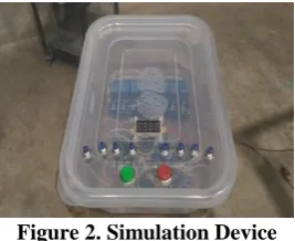
The simulator used in this study is compost of Arduino mega 2560 as processor or computer of the project which use 12volts DC electrical supply, 8 channel module that acts as an output device to operate the automotive relay which use a 5volts DC electrical supply, manual switch serves as an input device of the simulator and a 5 pins automotive relay that compost of two circuits, one for trigger circuit and the other one is the supply circuit. In this stage, the researcher asking for assistance of the computer programmer expert in programming and connecting the manual switch, arduino mega 2560 and the 8 channel relay module as one device. After connecting the major parts of the simulator, the researcher organized the wires and mounted them into one transparent box and then connected the relay module accordingly to the 5 pins automotive relay. The simulator consist of ten (10) manual switches, eight (8) push button switch that activates the eight (8) 5volts DC relay module individually, one (1) push button for pause functions of the simulator timer and one (1) push button for reset functions of the simulator device. The command of the simulator has eight different command depends on what push button will be press. One the first command, it consist of one cycle it started when the push button number one (1) were press, the Arduino mega 2560 will energized the relay number one (1) in the 8 channel relay within two (2) minutes, after two minutes arduino mega will de energize the relay number one and energizing the relay number two
[image:3.595.360.494.279.388.2](2) within two minutes. This command will repeat from relay number one, relay number two continuously until relay number eight (8) and the command will stop after relay number eight will energize. Second command is that you will press the push button number two (2) and the cycle will be the same but it will start in energizing the relay number two (2) and ends in relay number one (1). The reset button is used when the researcher decide to refresh or to start another command depends on the situation and the pause button is also used to pause the timer and command so that it allows the teacher and the student on its flexibility of the program. The researcher used transparent ready-made plastic enclosed box so that it can easily double check the function and operation of the simulator and make sure that the command will properly executed depends upon the input feed. Plastic box is highly recommended by the computer and programmer expert since it has good insulator and good materials in protecting the electronic parts inside.
Figure 2. Simulation Device
[image:3.595.354.496.439.564.2]Mounting of arduino mega 2560, manual switch and 8 channel relay in one box
Figure 3. Simulator Circuit
Actual electrical circuit of the automotive lighting system simulator
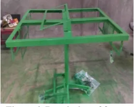
In this stage, since the automotive department has a lot of non-working, defective and obsolete automotive lighting system trainer. The researcher decided to select the non-usable existing automotive lighting system trainer with the following lighting system mountings like park and tail lamp, headlight bulb, turn signal light, brake light, reverse light, horn, and other accessory mountings like combination switch, manual and individual switches, flasher relays and relays, fuse box and battery that will fit to the current project and convert it as functional. Figure 4. Shows the repainting job of the old automotive lighting system trainer so that the new project will be safe for troubleshooting experience of the student. After repainting session, the researcher installed back the functional parts such as headlight assembly, park and tail light assembly, turn signal light assembly, brake and reverse light assembly. New automotive lighting assembly is installed such as dome light assembly, dashboard, combination switch, hazard switch, reverse switch, brake light switch assembly, relays, flasher relay, Horn, fuse and fuse box, improvised door and door switch and electrical wirings as well as junctions.
Figure 4. Repainting of frame Stage 3
stage involves connecting the 8 channel relay module and the automotive relay to the electrical wire of the automotive lighting system circuit. This project development used eighteen (18) special automotive relay that has 5 pins with normally closed contact. The purpose of relay that has 5 pins with normally closed contact is the responsible in cutting the circuit of the automotive lighting wire. In this project development each relay in 8 channel relay module can operate two 5 pins relay except on the relay number seven (7) and eight (8) that can operate three 5 pins relay. In this stage, careful planning, designing and wiring are needed since this is the critical path in obtaining the desired functions and operations of the simulator device and the automotive lighting system. Physical factors like mounting the simulator device, location of the automotive relay which part of the simulator, wire connections from simulator relay and designated automotive lighting system circuit wiring was considered. After considering the physical factors, connecting the wires between the simulator and the automotive lighting system circuit was followed. In this portion, to ensure proper connection and good conductivity in every connection the researcher always soldered the wires with the used of soldering iron and lead so that it will not cause problem during normal operation and during troubleshooting.
B. Mechanical Design
Figure 5. Front view and measurement of the frame
[image:4.595.334.518.316.611.2]Figure 6. Rear view and measurement of the frame
Figure 7. Right side view of the frame
Figure 8. Top view and dashboard details
C. Design of the automotive lighting system with indicated trouble
[image:4.595.99.238.317.428.2]Park/tail light
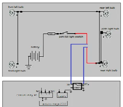
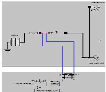
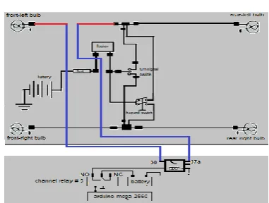
[image:5.595.336.517.207.365.2]1. Park/tail light circuit: Normally when park/tail light switch is turn on, front, rear and plate light will iluminate if the circuit is complete from the battery, switch, load and ground. In Figure 9. when arduino mega 2560 command the channel relay number one (1), the coil of the relay on the simulator will energize and the contact will shift its connection from 87a to 87 and that makes the wire from the switch junction to main load junctions cut. In this manner when the student will turn on the park/tail switch, all of the bulb will not illuminate causes and that’s the time they will diagnose, identify and repair the wire. In Figure 10. when the 8 channel relay number eight (8) will energize the relay coil that causes open circuit of the wire from front-left bulb junction to the front-right bulb junction and the front-right bulb will not illuminate. The red line on the park/tail light circuit is the wire that will open circuit when simulator executes trouble on the automotive lighting system. The blue line is a wire that connects the simulator to the automotive lighting system circuit.
[image:5.595.67.271.301.479.2]Figure 9. Park/tail light and simulator circuit (SET 1)
Figure 10. Park/tail light and simulator circuit (SET 2) Head light
3. Head light: Headlight circuit is divided into two different circuit namely low beam circuit and the high beam circuit. Low beam bulb will illuminate when there is a complete circuit from the battery, headlight switch, low beam switch, low beam relay, low beam bulb and ground. Also, high beam bulb will illuminate when there is a
complete circuit from the battery, head light switch, high beam switch, high beam relay, high beam bulb and ground. In Figure 11. when the channel relay number two (2) is activated by arduino mega 2560, the relay of the simulator will cut the connection from the high beam relay junction to the high beam bulb junction causing troubles on the circuit and in effect the entire high beam bulb will not illuminate. In set two (2) figure 12., when channel relay number one (1) will activate the relay of the simulator energized to cut the connection of the wire from the front-left side juction to the front-right low beam bulb junction that causes no illumination of the front-right low beam bulb.
Figure 11. Headlight and simulator circuit (SET1)
Figure 12. Headlight and simulator circuit (SET2) Turn signal
Figure 13. Turn signal light and simulator circuit (SET 1)
Figure 14. Turn signal light and simulator circuit (SET 2) Brake light
[image:6.595.95.242.214.347.2]5. Brake light: The brake light bulb will illuminate when the electrical connection is complete from the battery, brake light switch, brake light bulb and ground. this will happen in regular design when the driver depressed the brake pedal, in this design researcher made an innovation so that the student will operate it easily through hand operation. Figure 15. shows the actual circuit in brake light with the simulator, in this circuit the channel relay number four (4) will activate then causing the relay of the simulator to energize and cuts the wire from the rear-right junction to the rear-left junction and in effect the rear-left bulb will not illuminate when brake switch is turn on. In Figure 16., channel relay number three (3) energized to operate the relay of the simulator then cuts the connection of the wire from the fuse junction to brake light switch junction causing the entire brake light bulb not to illuminate.
Figure 15. Brake light and simulator circuit (SET 1)
Figure 16. Brake light and simulator circuit (SET 2) Reverse light
[image:6.595.339.512.413.555.2]7. Reverse light: reverse light bulb illuminates when the driver shift the transmission lever from forward selection to the reverse selection, this inform the other road user that the vehicle will move backward. In this study, researcher used toggle switch to turn the reverse light bulb to ON. Figure 17, shows the actual circuit on how the simulator creates the trouble by cutting the electrical connection from the fuse junction to the reverse switch junction this happens when channel relay number five (5) activates. Also in Figure 18., wire from reverse switch junction to the main load junction is cut through relay of the simulator. The relay of the simulator operate when channel relay number four (4) will activate.
[image:6.595.331.521.582.733.2]Figure 17. Reverse light and simulator circuit (SET 1)
[image:6.595.87.252.591.733.2]Hazard light
8. Hazard light: Hazard light circuit is incorporated circuit in the turn signal light since the components and electrical circuit are the same. Additional components is the hazard switch thus when it turn ON the entire turn signal bulb will illuminate. The circuit compost of battery, flasher relay, hazard switch, turn signal light bulb and ground. Figure 19, shows the exact wire location when the hazard has a fault during the simulator activates. This happen when channel relay number six ( 6) activates causing the relay of the simulator will energize and cuts the wire from fuse junction to the flasher junction and in effect the entire turn signal light bulb will not illuminate. Also in Figure 20., the wire in the right side junction to the front-left bulb junction is cut when channel relay number five (5) activates causing the front-left bulb will not illuminate during hazard switch is turn ON.
[image:7.595.326.527.85.255.2]Figure 19. Hazard light and simulator circuit (SET 1)
Figure 20. Hazard light and simulator circuit (SET 2) Horn circuit
9. Horn circuit : Horn circuit consist of battery, horn switch, horn evice and ground. The horn will generate sounds when electrical circuit is completed through horn switch. In figure 21., shows the complete circuit of horn with the circuit of the simulator. The trouble starts when the channel relay number seven (7) is activated by the arduino mega 2560 causing the relay of the simulator energize and cuts the wire from the horn switch to the horn relay. Also in Figure 22., it shows the complete circuit of the horn circuit with the simulator connection. In this portion when the channel relay number number six (6) activates then operates the relay of the simulator to cut the wire from the fuse junction to the relay junction and in effect the horn will not
[image:7.595.75.260.267.422.2]work even if it turn On the horn switch unless it will replace and connect another wire.
Figure 21. Horn and simulator circuit (SET 1)
Figure 22. Horn and simulator circuit (SET 2) Dome light
[image:7.595.334.518.280.517.2] [image:7.595.72.263.442.586.2]Figure 23. Dome light and simulator circuit (SET 1)
Figure 24. Dome light and simulator circuit (SET 2) Door light
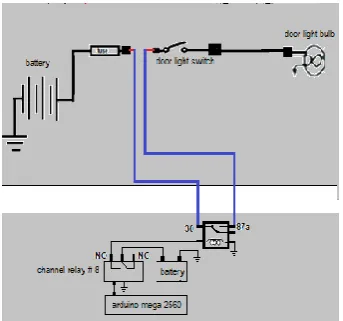
11. Door light: The door light use to inform the driver and passenger about the status of the vehicle door position. Door lamp will illuminate in the dashboard panel if one of the door is patially to fully open. The circuit is compost of battery, door light switches, door light bulb in the dashboard panel in front of the driver. Figure 25. And 26., shows the electrical connection of the relay simulator and the door light. InFigure 25., channel relay number eight (8) will activate and in Figure 26., the channel relay that will activate is the relay number seven (7) causes the same trouble by cutting the wire from the fuse junction to the door light switch and in effect the door lamp will not illuminate even if the door is open.
Figure 25. Door light and simulator circuit (SET 1)
Figure 26. Door light and simulator circuit (SET 2)
III. RESULTS & DISCUSSION
Problem 1. What is the respondents’ characteristics in terms of;
1.1. Gender 1.2 Year level 1.3 Scholarship status 1.4 Monthly Family income 1.5 Number of units 1.6 Purpose of taking course 1.7 Attendance
[image:8.595.82.257.51.196.2]1.8 Participation
Table 1 Distribution of statistics frequency and percentage distribution on
Respondents Characteristics in terms of Gender, Year Level and Scholarship Status
Specification Specifications Frequency Percentage
Gender Male 25 56.82%
Female 19 43.18%
Total 44 100.00%
Year level 1st year 0 0.00%
2nd year 0 0.00%
3rd year 44 100.00%
4th year 0 0.00%
Total 44 100.00%
Scholarship Status
None 42 95.45%
Dean’s List 0 0.00%
Chancellor’s List 2 4.55%
Rizal’s List 0 0.00%
Total 44 100.00%
[image:8.595.83.255.577.737.2]The data shows that all the respondents are third year student, majority fifty-seven percent (57%) of the respondents are male. And ninety-five percent have no scholarship status.
Table 2 Distribution of statistics frequency and percentage distribution on
Specification Specifications Frequency Percentage Father’s
Monthly income
None 5 11.36%
5000 and below 18 40.91%
5,001-10,000 13 29.55%
10,001-15,000 6 13.64%
15,001-20,000 2 4.55%
20,001-25,000 0 0.00%
25,001 and above 0 0.00%
Total 44 100.00% Mother’s
Monthly income
None 15 34.09%
5000 and below 20 45.45%
5,001-10,000 7 15.91%
10,001-15,000 0 0.00%
15,001-20,000 1 2.27%
20,001-25,000 1 2.27%
25,001 and above 0 0.00%
Total 44 100.00% Current
number of Units
14 and below 7 15.91%
15-17 8 18.18%
18-20 4 9.09%
21-24 23 52.27%
25 and above 2 4.55%
Total 44 100.00%
Purpose of taking the course
No slots available 21 47.73% Most of friends are
taking the course 0 0.00%
Job demand 10 22.73%
Work abroad 8 18.18%
Sustain/provide the
needs of family 5 11.36%
Total 44 100.00%
[image:9.595.46.305.47.462.2]The data shows that majority fifty-two percent (52%) of the respondents’ fathers monthly income is from none to 5,000 and below. Majority seventy-nine percent (79%) of the mother’s monthly income is also from none to 5,000 and below. The data further shows that majority fifty-two percent (52%) of the respondents’ current number of units is 21-24. The data also shows that though s substantial number of student took the course because of No available slots, but majority fifty-two percent (52%) took the course because of job demand, work abroad, and to sustain and provide for family.
Table 3 Distribution of statistics frequency and percentage distribution on
Respondents Characteristics in terms of attendance and participation
Specification Specifications Frequency Percentage
Attendance 2 0 0.00%
3 0 0.00%
4 0 0.00%
5 2 4.55%
6 6 13.64%
7 20 45.45%
8 16 36.36%
Participation 25-30 Very good 16 36.36%
19-24 Good 19 43.18%
13-18 Fair 8 18.18%
7-12 Poor 1 2.27%
0-6 Very Poor 0 0.00%
44 100.00%
The data shows that majority eighty-two percent of the respondents’ attendance is from 7 to 8. And the data also shows that majority eighty percent (80%) of the respondents score in participation during the study in from 19-30, classified as good to very good.
Problem 2 what is the respondents Pretest written and practical score in terms of
2.1 Park/tail 2.2 head 2.3 turn signal 2.4 brake 2.5 reverse 2.6 hazard 2.7 horn 2.8 dome light 2.9 door light
Table 4 Distribution of Statistics, Frequency, percentage distribution, mean, percentage of correct responses and standard deviation on respondents Pretest written score Range Description Frequency Percentage
distribution
17-20 Very good 0 0.00%
13-16 Good 4 9.09%
9-12 Fair 29 65.91%
5-8 Poor 11 25.00%
0-4 Very Poor 0 0.00%
44 100.00%
Mean 9.98
Standard Deviation 1.96
HEADLIGHT Percenta
ge of correct response
s
Standar d Deviati
on
1. Type of automotive lighting that provides high illumination during night time. It has a
high beam and low beam operation. 100.00% 0.00 2. Which of the following is a circuit device
that helps protect the head light switch by operating the high current load through low
current supply? 54.55% 0.50
3. . In most modern automobiles, the chassis can act as a ground because it is connected
to 81.82% 0.39
PARK/TAIL
4. Which of the following circuit is incorporated to the operation of headlight
[image:9.595.304.550.50.126.2]5. Which of the following is not part of the
park and tail light circuit 77.27% 0.42
TURN SIGNAL
6. A device that provides flashing action of
the hazard and turn signal light 70.45% 0.46 7. Where is the location of turn signal light
switch 31.82% 0.47
BRAKE LIGHT
8. Which of the following is the best way to
describe the brake light 63.64% 0.49
9. Which of the following lamp that
provides backups the brake light operation 6.82% 0.25 REVERSE LIGHT
10. Reverse light will ON if the driver turns the shift lever to reverse position. Where is
the location of the reverse switch 47.73% 0.51 11. What is the purpose of reverse lamp in
an automotive lighting system 59.09% 0.50 HAZARD LIGHT
12. When the hazard switch is turn ON.
What lamp will illuminate 88.64% 0.32
13. In what instances thus the hazard light
will turn ON 70.45% 0.46
HORN
14. Horn sounds is measured through unit decibels. What is the standard decibels of
automotive horn 9.09% 0.29
15. What type of switch use in the horn
circuit 38.64% 0.49
16. Which of the following do automotive
horns use to operate 9.09% 0.29
DOME
17. Which of the following is the correct
pathways of dome light circuit 31.82% 0.47 Indicator
17. Which is true about dome light 9.09% 0.29 DOOR
18. The door lamp indicator in the dash
board will illuminate when 81.82% 0.39
19. Which of the following best describe the
door lamp 15.91% 0.37
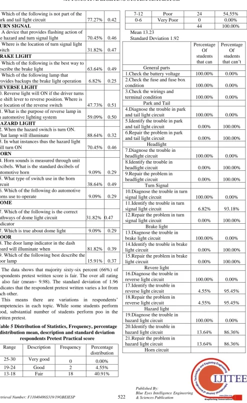
The data shows that majority sixty-six percent (66%) of respondents pretest written score is fair. The over all rating is also fair (mean= 9.98). The standard deviation of 1.96 indicates that the respondent pretest written varies a lot from each other.
[image:10.595.54.549.29.837.2]This means there are variations in respondents’ competencies in each topic. While some students perform good, substantial number of students perform poo in the written pretest.
Table 5 Distribution of Statistics, Frequency, percentage distribution mean, description and standard deviation
respondents Pretest Practical score
Range Description Frequency Percentage distribution
25-30 Very good 0 0.00%
19-24 Good 2 4.55%
13-18 Fair 18 40.91%
7-12 Poor 24 54.55%
0-6 Very Poor 0 0.00%
44 100.00%
Mean 13.23
Standard Deviation 1.92
Percentage Of students that can
Percentage Of students that can’t General parts
1.Check the battery voltage 100.00% 0.00% 2.Check the fuse and fuse box
condition 100.00% 0.00%
3.Check the wirings and
terminal condition 100.00% 0.00%
Park and Tail 4.Diagnose the trouble in park
and tail light circuit 100.00% 0.00% 5.Identify the trouble in park
and tail light circuit 0.00% 100.00%
6.Repair the problem in park
and tail light circuit 0.00% 100.00%
Headlight 7.Diagnose the trouble in
headlight circuit 100.00% 0.00%
8.Identify the trouble in
headlight circuit 0.00% 100.00%
9.Repair the problem in
headlight circuit 0.00% 100.00%
Turn Signal
10.Diagnose the trouble in turn
signal light circuit 100.00% 0.00%
11.Identify the trouble in turn
signal light circuit 6.82% 93.18%
12.Repair the problem in turn
signal light circuit 0.00% 100.00%
Brake light 13.Diagnose the trouble in
brake light circuit 100.00% 0.00%
14.Identify the trouble in brake
light circuit 0.00% 100.00%
15.Repair the problem in brake
light circuit 0.00% 100.00%
Revere light 16.Diagnose the trouble in
reverse light circuit 100.00% 0.00%
17.Identify the trouble in
reverse light circuit 4.55% 95.45%
18.Repair the problem in
reverse light circuit 4.55% 95.45%
Hazard light 19.Diagnose the trouble in
hazard light circuit 100.00% 0.00%
20.Identify the trouble in
hazard light circuit 13.64% 86.36%
21.Repair the problem in
hazard light circuit 13.64% 86.36%
22.Diagnose the trouble in
horn circuit 100.00% 0.00%
23.Identify the trouble in horn
circuit 4.55% 95.45%
24.Repair the problem in horn
circuit 4.55% 95.45%
Dome light 25.Diagnose the trouble in
dome light circuit 100.00% 0.00%
26.Identify the trouble in dome
light circuit 15.91% 84.09%
27.Repair the problem in dome
light circuit 15.91% 84.09%
Door light 28.Diagnose the trouble in
door light circuit 100.00% 0.00%
29.Identify the trouble in door
light circuit 20.45% 79.55%
30.Repair the problem in door
light circuit 18.18% 81.82%
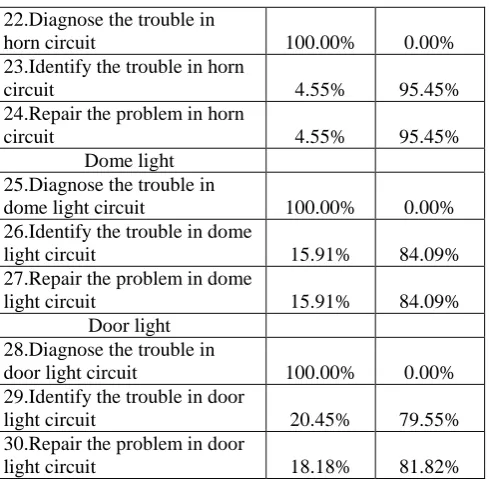
The data shows that majority fifty-five percent (55%) of respondents pretest practical score is poor. The over-all rating is categorically fair (mean= 13.23). The standard deviation of 1.92 indicates that the respondent pretest practical score varies a lot from each other.
The data further shows that more than eighty percent (80%) cannot perform practical test in most competencies. While a number of competencies where accomplished by most respondents, this is because these classified competencies are very basic. But as the competency measure in pretest practical test increase in difficulty. Their capacity to perform as desired decrease.
Problem 3 What is the respondents Post-test written and practical score in terms of
[image:11.595.45.290.47.289.2]2.1 Park/tail 2.2 head 2.3 turn signal 2.4 brake 2.5 reverse 2.6 hazard 2.7 horn 2.8 dome light 2.9 door light
Table 6 Distribution of Statistics, Frequency, percentage distribution mean, description and standard deviation
respondents Posttest written score
Range Description Frequency Percentage distribution
17-20 Very good 35 79.55%
13-16 Good 9 20.45%
9-12 Fair 0 0.00%
5-8 Poor 0 0.00%
0-4 Very Poor 0 0.00%
44 100.00%
Mean 17.95
Standard Deviation 1.58
HEADLIGHT
Percentage of Correct Responses
SD
1. Type of automotive lighting that 100.00% 0.00
provides high illumination during night time. It has a high beam and low beam operation.
2. Which of the following is a circuit device that helps protect the head light switch by operating the high current load
through low current supply? 100.00% 0.00 20. In most modern automobiles, the
chassis can act as a ground because it is
connected to 90.91% 0.29
PARKTAIL
3. Which of the following circuit is incorporated to the operation of headlight
switch? 93.18% 0.25
4. Which of the following is not part of
the park and tail light circuit 79.55% 0.41 TURN SIGNAL
5. A device that provides flashing action
of the hazard and turn signal light 93.18% 0.25 6. Where is the location of turn signal
light switch 90.91% 0.29
BRAKE LIGHT
7. Which of the following is the best way
to describe the brake light 90.91% 0.29
8. Which of the following lamp that
provides backups the brake light operation 72.73% 0.45 REVERSE LIGHT
9. Reverse light will ON if the driver turns the shift lever to reverse position. Where
is the location of the reverse switch 84.09% 0.37 10. What is the purpose of reverse lamp in
an automotive lighting system 84.09% 0.37 HAZARD LIGHT
11. When the hazard switch is turn ON.
What lamp will illuminate 95.45% 0.21
12. In what instances thus the hazard light
will turn ON 93.18% 0.25
HORN
13. Horn sounds is measured through unit decibels. What is the standard decibels of
automotive horn 93.18% 0.25
14. What type of switch use in the horn
circuit 84.09% 0.37
19. Which of the following do automotive
horns use to operate 95.45% 0.21
DOME
15. Which of the following is the correct
pathways of dome light circuit 86.36% 0.35 Indicator
16. Which is true about dome light 86.36% 0.35 DOOR
17. The door lamp indicator in the dash
board will illuminate when 88.64% 0.32
18. Which of the following best describe
the door lamp 93.18% 0.25
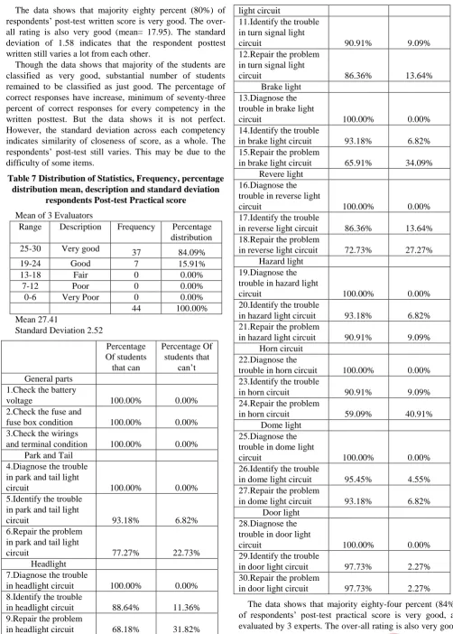
The data shows that majority eighty percent (80%) of respondents’ post-test written score is very good. The over-all rating is also very good (mean= 17.95). The standard deviation of 1.58 indicates that the respondent posttest written still varies a lot from each other.
[image:12.595.40.543.45.747.2]Though the data shows that majority of the students are classified as very good, substantial number of students remained to be classified as just good. The percentage of correct responses have increase, minimum of seventy-three percent of correct responses for every competency in the written posttest. But the data shows it is not perfect. However, the standard deviation across each competency indicates similarity of closeness of score, as a whole. The respondents’ post-test still varies. This may be due to the difficulty of some items.
Table 7 Distribution of Statistics, Frequency, percentage distribution mean, description and standard deviation
respondents Post-test Practical score Mean of 3 Evaluators
Range Description Frequency Percentage distribution
25-30 Very good 37 84.09%
19-24 Good 7 15.91%
13-18 Fair 0 0.00%
7-12 Poor 0 0.00%
0-6 Very Poor 0 0.00%
44 100.00%
Mean 27.41
Standard Deviation 2.52
Percentage Of students that can
Percentage Of students that
can’t General parts
1.Check the battery
voltage 100.00% 0.00%
2.Check the fuse and
fuse box condition 100.00% 0.00%
3.Check the wirings
and terminal condition 100.00% 0.00% Park and Tail
4.Diagnose the trouble in park and tail light
circuit 100.00% 0.00%
5.Identify the trouble in park and tail light
circuit 93.18% 6.82%
6.Repair the problem in park and tail light
circuit 77.27% 22.73%
Headlight 7.Diagnose the trouble
in headlight circuit 100.00% 0.00%
8.Identify the trouble
in headlight circuit 88.64% 11.36%
9.Repair the problem
in headlight circuit 68.18% 31.82%
Turn Signal 10.Diagnose the
trouble in turn signal 100.00% 0.00%
light circuit
11.Identify the trouble in turn signal light
circuit 90.91% 9.09%
12.Repair the problem in turn signal light
circuit 86.36% 13.64%
Brake light 13.Diagnose the trouble in brake light
circuit 100.00% 0.00%
14.Identify the trouble
in brake light circuit 93.18% 6.82% 15.Repair the problem
in brake light circuit 65.91% 34.09% Revere light
16.Diagnose the trouble in reverse light
circuit 100.00% 0.00%
17.Identify the trouble
in reverse light circuit 86.36% 13.64% 18.Repair the problem
in reverse light circuit 72.73% 27.27% Hazard light
19.Diagnose the trouble in hazard light
circuit 100.00% 0.00%
20.Identify the trouble
in hazard light circuit 93.18% 6.82% 21.Repair the problem
in hazard light circuit 90.91% 9.09% Horn circuit
22.Diagnose the
trouble in horn circuit 100.00% 0.00% 23.Identify the trouble
in horn circuit 90.91% 9.09%
24.Repair the problem
in horn circuit 59.09% 40.91%
Dome light 25.Diagnose the trouble in dome light
circuit 100.00% 0.00%
26.Identify the trouble
in dome light circuit 95.45% 4.55%
27.Repair the problem
in dome light circuit 93.18% 6.82%
Door light 28.Diagnose the trouble in door light
circuit 100.00% 0.00%
29.Identify the trouble
in door light circuit 97.73% 2.27%
30.Repair the problem
in door light circuit 97.73% 2.27%
(mean= 27.41). The standard deviation of 2.52 indicates that the respondent post-test practical as evaluated by 3 experts varies a lot from each other.
The data shows though majority of the respondents are can in all competencies. There are instances that a number of respondent cannot perform as desired by the experts. Considering that there are three experts, this mean three different level of high standards. This is perhaps would explain the standard deviation of 2.52. However as a whole the respondent posttest practical is classified as very good.
[image:13.595.45.294.251.337.2]Problem 4. Is there any significant difference in respondent’s pre-test and post-test written and practical scores?
Table 8 Distribution of statistic (one-tailed T-test) written and practical scores when grouped according to
type of test
category Groups P-value T stat
Pretest Posttest Written n=44
Mean=9.97
n=44 Mean=17.95
4.7X10⁻³⁵ 21.00**
Practical n=44 Mean=13.23
n=44 Mean=27.41
2.64X10-45 20.73**
** highly significant
The table shows the distribution of statistics (one tailed T-test) written and practical scores when grouped according to type of test. There were two groups being compared: pretest and posttest.
The null hypothesis, there is that the pretest written is greater than the posttest written is rejected. The result indicates that the posttest written is significant higher than the pretest written (T=20.00**).
In addition, in terms of practical test, the null hypothesis, there is that the pretest practical is greater than the posttest practical is rejected. The result indicates that the posttest practical is significant higher than the pretest practical (T=20.73**).
Based on the test-statistics in can be inferred that the trainer has been very effective increasing respondents score both in written and practical evaluation.
Problem 5. To what extend does input and process variable explain the results in the output variable?
Table 9 Multiple linear regression analysis between the whole set of input and process variable and respondents
output variable Post-test written Independent
variable
Regression coefficient
P- Value T- Value
Gender 0.60 0.2645 1.134NS
Father's income 0.27 0.3199 1.009NS
Mother's income -0.16 0.5156 -0.657NS
Current # of units -0.04 0.8635 -0.173NS Purpose of taking
course 0.09 0.6490 0.459NS
Total attendance 0.41 0.2220 1.244NS
Participation 0.14 0.0233 2.374*
Pretest written 0.00 0.9988 0.002NS
Pretest practical 0.05 0.7004 0.388NS
NS Not significant * Significant Constant : 12.99
Adjusted R : 0.13
F- Value: 1.68 P-value: 0.130
Significance Level: Not significant
The Table shows that the regression model is not significant. The null hypothesis is accepted. This signifies that input and process variable have no significant effect on respondents’ posttest written.
The value of adjusted coefficient of multiple determination is 0.13 which explains that 13% of the total variation of respondents’ output variable is explained by the variation input and process variable. The remaining 87% percent can be explained by other reasons or variables.
This basically means that respondent written post-test is not influenced or affected by the respondents Gender, Father's income, Mother's income, Current # of units, Purpose of taking course, Total attendance, Pretest written and Pretest practical. However, individually participation have a significant effect in respondents’ post-test written.
[image:13.595.304.552.424.560.2]Though in most instances, input and process variable affects the output variable, however in this study only participation have a significant effect in respondents written posttest. This maybe due to the fact that since most of the respondents are male, have a strong tendency to be less pragmatic would constitute to the result in the model. It is also possible that the respondents written practical score can be affected with strong direct relationship to the competencies such as their participation during the study.
Table 12 Multiple linear regression analysis between the whole set of input and process variable and respondents
output variable Post-test written Independent
variable
Regression coefficient
P- Value T- Value
Gender 0.92 0.2895 1.076
Father's income 0.52 0.2398 1.196
Mother's income -0.04 0.9247 -0.095
Current # of units 0.86 0.0347 2.200* Purpose of taking course 0.68 0.0354 2.190*
Total attendance 1.42 0.0123 2.641**
Participation 0.02 0.7915 0.266
Pretest written 0.27 0.2102 1.277
Pretest practical 0.22 0.3064 1.038
NS Not significant * Significant ** Highly Significant Constant : 4.04
Adjusted R : 0.10 F- Value: 1.52 P-value: 0.178
Significance Level: Not significant
The Table shows that the regression model is not significant. The null hypothesis is accepted. This signifies that input and process variable have no significant effect on respondents’ posttest practical.
[image:13.595.46.293.602.758.2]Though as a whole there is so no absolute bond between the theoretical model and respondents’ performance both in written and practical. There is significant and highly significant effect in individual variables to the respondents’ post-test practical exam. Specifically, on Current number of units, Purpose of taking course and attendance to practical posttest of students. And participation in written posttest.
Setting aside the theoretical model, IPO and focusing on the Outcome which is the innovation the automotive lighting simulator as a whole the study has been very effective. The posttest both written and practical is significantly greater than the pretest.
IV. CONCLUSIONS AND IMPLICATIONS
The trainer automotive lighting system simulator has been effective in increaing students performance based pretest posttest test statistics. The highly significant difference from pretest to posttest can be accounted to the trainer. Based on the data, though not all, some variables in the input and process out had significant, and highly significant effect on posttest written and practical.
V. RECOMMENDATIONS
On the basis of the findings the following recommendations are presented.
The administration is recommended to strengthen research innovation that enhances students’ performance.
Teachers are requested to innovate or use the automotive lighting system to address competency gap of the automotive student in automotive lighting system and providing relevant laboratory tools that replicate the ideal set up of automotive lighting system troubles, operations and circuits.
The students are highly motivated to maximize and appreciate actual visualization of the electrical lighting system set up and actual wire troubles, in order to familiarize the operation and behavior of its components.
REFERENCES CITED
1. Ajao, A., Bamgboyes, O., Kadiri, K. (2014). Local fabrication of digital logic trainer for lab demonstration.Washington DC: National Academics Press.
2. Back-up Light (n.d). Retrieved November 11, 2012 from http://autosytempro.com/exteriorlights.
3. Benzal et al. (2013). “The effectiveness of a toyota 4k cut-away manual transmission and clutch mock-up as a teaching-learning tool for the subject aet 133”. MSU-Iligan Institute of Technology. Iligan City.
4. Bransford J., Brown A. and Cocking R. (2000). How people learn: brain, mind, experience, and school. National Reasearch Council, Washington DC: National Academics Press.
5. Calinga et al. (2012). Evaluating the performance and effectiveness of an improvised water cooling system mock-up for a mitsubishi 4D56 diesel engine. MSU-Iligan Institute of Technology .Iligan City.
6. Diploma in Automotive Engineering Technology, n.d. Retrieved January 2015 from http://msuiit.edu.com/DAUET 7. Effectiveness, (2004). Retrieved December 12, 2009 from
http;//wikionlinethechnicaldictionary/effectiveness
8. Electrical Connector (n.d). Retrieved February 19, 2012 from http://en.wikipedia.org/wiki/Electrical_connector
9. Eusebio, L. (2014.) IPO framework. Retrieved December 23, 2017 from https://prezi.com/tggh0qiekksa/theoretical-framework-conceptual-framework-and-paradigm-of/
10. Fabrication, (2014). Retrieved December 10, 2014 from http://freeonlinetechicaldictionary/fabrication
11. Flasher, (2002). Retrieved September 6, 2013 from http://wikipedia.com.ph/flashers
12. Functionality (n. d). Retrieved February 12, 2013 from http://freeonlinetechicaldictionary/fabrication
13. Fuses, different types (2012). Retrieved November 7, 2011 fromhttp://www.electricaltechnology.org/2014/11/fuse-types-of-fuses.html#
14. Grabianowski, E. (2008). How brake light wiring works.
Retrieved August 11, 2001 from
http://howstuffworks/howbrakelightwiringworks/
15. Gutiérrez-Artacho, J., and Olvera-Lobo, M. (2017). Web Localization of Spanish SMEs: The Case of Study in Chemical Sector. Journal of Information Systems Engineering
& Management, 2(3), 15.
https://doi.org/10.20897/jisem.201715
16. Headlight Circuit (2000). Retrieved February 20, 2012 from http://6772chevytrucks.com/vboard/showthread.php?t=50928 5
17. Hollembeak, J. (2010). Retrived June 18, 2013 from http://howstuffworks.com/howbrakelightsfunctions.html 18. Hollembeak, J. and Evanjec C. (2002). Retrived March 11,
2011 from
http://howstuffworks.com/bulbsilluminates/autobulbs 19. Jones A. and Barlett, D. (2008).Park and tail light circuit (pp.
41-44). Burlington MA: Ascend Learning Company
20. Knowles L. and Don B. (2005).Techone: basic automotive service and maintenance. United States of America: Thomson Delmar Learning, Inc
21. Lighting Circuits (2011). Retrieved May 14, 2009 from http;//cdtextbook.com/electrical/chargStartLight/circuits/spcir cuit.html
22. Mirzamasoumzadeh, B., & Mollasadeghi, V. (2013). EFFECTS OF OSMOTIC STRESS ON CHLOROPHYLL AND PROLINE DIFFERENTWHEAT CULTIVARS, UCT Journal of Research in Science, Engineering and Technology, 1(1): 12-13.
23. Mukanbetkaliyev, A., Amandykova, S., Zhambaye, Y., Duskaziyeva, Z., & Alimbetova, A. (2018). The aspects of legal regulation on staffing of procuratorial authorities of the Russian Federation and the Republic of Kazakhstan. Opción, 34(85), 187-216.
24. Park, L. and Kimbrough P., (2011).Automotive wiring; A Practical Guide To Wiring Your Hot Rod Or Custom Car 4(11), 11-7. Minneapolis, USA.MBI Publishing Company. 25. Relay Wiring Basics (2008). Retrieved May 10,2010 from
http://tech.240sxone.com/relaydiagram
26. Switches (2002). Retrieved April 11. 2003 from
http://wikipediaonlineencyclopedia/electricalswitches 27. Shuttleworth (2009).Pretest-Posttest Designs. Retrieved
March 8, 2014 from Expolable.com:
https://explorable.com/pretest-posttest-designs
28. Turn Signals (n.d). Retrieved August 4,2009 from http://www.knucklebusterinc.com/features/2009/08/04/led-turn-signals/
29. Wordenweber,B., Wallaschek,J., BoyceP., Hoffman,D.
(2007). Automotive lighting and human vision
3rdedition.United States of America: Cengage Learning, Inc 30. Vieru, T.C (2009). Mock-up. Retrieved November 12, 2012