International Journal of Innovative Technology and Exploring Engineering (IJITEE) ISSN: 2278-3075, Volume-8 Issue-6, April 2019
DC Motor Speed Control using PID Controller,
IR Sensor and PWM Hysteresis
Hardik S Jain, AkshatPalak, SandeshAgrawal, Krishnam Tibrewal, Malaya Kumar Hota
Abstract: Due to shortcomings of low accuracy and response lag in various methods of the DC motor speed control, a comparison between different methods of DC motor speed control will be carried out. The Proportional Integral Differential (PID) controller design and selection of various Proportional, Integral and Differential control parameters according to various system responses is proposed in this paper. MATLABis a multi-paradigm numerical computing environment and proprietary programming language. It allows matrix manipulations, plotting of functions and data, implementation of algorithms. An additional package, Simulink, adds graphical multi-domain simulation and model-based design for dynamic and embedded systems. We are using Simulink to implement the Proportional Integral Differential (PID) controller that can be used to control the speed of DC motor and bring it at the desired speed. Pulse width Modulation (PWM) is another technique which involves the use of the same simulation software. Hardware implementation requires the use of Infrared (IR) sensors and Arduino (open source platform for building Electronic project) for measuring the Rotations per minute (RPM) of the DC motor. Motor speed was measured using three techniques and a further comparison between these techniques is carried out according to the desired and control speed.The applications of our research could be in conveyors, turntables and others for which adjustable speed and constant or low-speed torque are required. It also works well in dynamic braking and reversing applications, which are common in many industrial machines.
Index Terms: Matlab, Motor, IR(Infrared), PID (Propor-tional Integral Derivative), PWM (Pulse width modulation) hysteresis, RPM (Rotations per minute), Simulink.
I. INTRODUCTION
The reason to control the speed of the engine is to conquer the issue in the industry like to maintain a strategic distance from machines harms and to stay away from the moderate ascent time and high overshoot. This is on account of when the beginning voltage is high, it isn‟t
Revised Manuscript Received on April 07, 2019.
Hardik S Jain, Student, Department of Communication Engineering, School of Electronics Engineering, Vellore Institute of Technology, Vellore 632014, Tamil Nadu, India.
Akshat Palak, Student, Department of Communication Engineering, School of Electronics Engineering, Vellore Institute of Technology, Vellore 632014, Tamil Nadu, India.
SandeshAgrawal, Student, Department of Communication Engineering, School of Electronics Engineering, Vellore Institute of Technology, Vellore 632014, Tamil Nadu, India.
Krishnam Tibrewal, Student, Department of Communication Engineering, School of Electronics Engineering, Vellore Institute of Technology, Vellore 632014, Tamil Nadu, India.
Malaya Kumar Hota, Professor, Department of Communication Engineering, School of Electronics Engineering, Vellore Institute of Technology, Vellore 632014, Tamil Nadu, India.
reasonable for a machine as it can make machine harms. In this way, a controller like PID is created to beat this issue.
The PID controllers always have been broadly utilized for control of speed in dc engine. In all strategies the speed is controlled by monitoring the armature voltage, armature present, terminal voltage and by control-ling the field current of dc engine. Numerous experimental techniques are utilized for tuning of the PID parameters like inherited calculation, GSA calculation, ICA calculation, fluffy tuning, microcontroller tuning and so forth the yield for the speed control is gotten through the expansion of rotor shaft. Speed regulator of dc engine was having an issue with different information sources and controlling factors for speed. Some of the methods which can be used to control DC motor speed are:
Flux control method
Variable resistance in series with motor Voltage control method Using IR sensor and Arduino
Using MATLAB and Simulink (PID controller) Using PWM Hysteresis
Using Fuzzy logout of these, this paper will focus on three techniques and compare their results. They include IR sensor and Arduino method (hardware), PID
controller and PWM Hysteresis (software).
II. THEORY AND LITERATURE SURVEY
Three techniques have been used to control the speed of the DC motor, one involving a PID controller, other involv-ing PWM hysteresis and hardware implementation using IR sensor. We are going to discuss the theory related to PID controller, PWM hysteresis and IR sensor.
A. PID Controller
A proportional integral subsidiary controller (PID controller) is generally utilized as a part of mechanical control frameworks. It is a bland control circle criticism instrument and utilized as input controller. PID working standard is that it figures blunder esteem from the handled estimated esteem and the coveted reference point. Crafted by the controller is to limit the blunder by changing in the contributions of the framework. In the event that the framework isn‟t plainly known at that point applying PID controller give the best comes about in the event that it is tuned legitimately by keeping parameters of the framework as per the idea of the framework[1].
The PID estimation relies on three parameters which is known as the corresponding, the indispensable and subordinate part which is called P, I and D part. P decides the response to current
late showed up blunders, D determines response as indicated by the rate off blunder evolving. The aggregate of each of the three sections contribute the control instrument, for example, speed control of an engine in which P esteem relies on current mistake, I on the gathering of past mistake and D anticipate future blunder in light of the current rate of progress. As subsidiary activity is touchy to commotion so generally the controllers are PI controller instead of PID as it is unrealistic a framework without aggravations. Vital part makes a difference in the framework to reach onto its objective esteem while P part increment overshoots. The P expression takes the yield to corresponding of blunder esteem. Its reaction can be balanced by increasing the blunder by a consistent Kp which is called relative pick up. In the event that relative pick up isextensive then it makes a high overshoot which temperamental the framework, while a little yield change influences a little control to activity.
The error constants that the PID helps in rectifying are named as Kp, Kp and Kd.
B. PWM Hysteresis
Switch mode controllers are favored in applications like audio power amplifiers, inverters and motors due to their high efficiency and low system design cost. The active components in a switching converter are controlled by PWM signals applied to their gates. The duration for which the switches remain on is determined by the duty cycle of the Pulse Width Modulation signals, which in turn controls the energy delivered to the load [2]. The major share of the energy received by the load will be a function of the modulation only if the switching frequency is ensured to be much higher than the modulating signal frequency. The major points of comparison between various modulation schemes are switching losses, power supply utilization, control linearity and harmonic content in the output.
TABLE I
DEPENDANCE OF PID CONSTANTS ON CHARACTERISTICS
Response Rise Time Overshoot SettlingTime S-S Error
Kp Decrease Increase Small Change Decrease
Ki Decrease Increase Increase Eliminate
Kd Small Change Decrease Decrease No Change
Most noteworthy execution is accomplished with self os-cillating simple modulators, which makes utilization of no outer carrier signal. Self-oscillating modulators are also called locked loop circuit with pick up and stage attributes that guarantee a shut circle swaying. [3] The oscillation begins consequently when the additional phase contribution approaches -90. [4] Standard PWM modulators have achievable open loop bandwidth in the scope of fs/10 or fs/pi, where fs is the switch-ing frequency. In specific applications, this requires a high changing recurrence to give enough control circle transmission capacity to wanted dynamic execution. Self oscillating mod-ulators have open circle transmission capacity of the request of fs which settles on it a perfect decision for applications requiring astounding dynamic capacities.
III. RESULTS AND DISCUSSION
A. PID controller
The figure 1 is the feedback system of working of the PID controller and equation 1 explains how the three constants Kp, Ki and Kdare involved in controlling the speed of the motor.
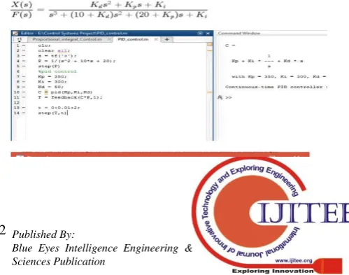
[image:2.595.314.551.219.293.2]The table gives the dependence of the characteristics of the PID controller on the three constants. The controller of the system given by C(s) is generated using the Matlab code given in figure 2.
Fig. 1:- The feedback system of PID controller.
Fig. 2:- Calculation of transfer function.
[image:2.595.301.551.643.839.2]International Journal of Innovative Technology and Exploring Engineering (IJITEE) ISSN: 2278-3075, Volume-8 Issue-6, April 2019
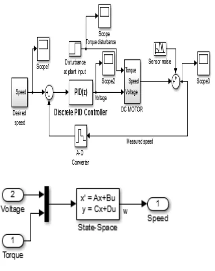
Fig. 3:- Step Response of the PID Controller. Matlab thus generates the transfer function and finds the step response of the PID controller Now using Simulink the speed control of the DC motor using PID controller is implemented as shown in figure 4.
[image:3.595.54.268.194.463.2]The Discrete PID controller is used to measure the Speed, Torque and Voltage of the DC motor and then send it back as feedback. The implementation of the speed block is shown in figure 5. Using this feedback the difference between the set speed and actual speed is slowly removed.
Fig 4:- Implementation of DC motor
[image:3.595.304.554.396.546.2]Fig 5:-Implementation of Speed Block.
Fig.6:- Parameters for PID Control before Tuning.
Fig 7:- Parameters for PID control after tuning
PID controller will analyze the error signal between measured speed and desired speed and this error signal is used to calculate the voltage required to command the motor and there is modelling of sensor noise in measurement channel And since the control system is digital there is also modelling of A-D converter which has sampling time of 0.02 sec using Zero order hold block The sampling time of PID controller is same as A-D converter.
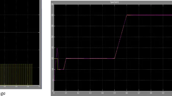
Fig 8 shows that when we have taken the output our control system is not working properly as it is not measuring speed properly with respect to desired speed. Fig 9 shows that after tuning as it improves the performance of our control system it is also tracking well our measured speed with respect to our desired speed. But it is still not good enough to be used in major applications. At 200 RPM the motor speed turns out to be 100 RPM.
Figure 8:- Desired speed VS Measured speed before tuning
B. PWM Hysterisis
[image:3.595.61.278.639.723.2]Fig. 9:- Desired Speed Vs. Measured Speed after Tuning.
[image:4.595.307.544.254.427.2]Fig 10:- Feedback Circuit of Speed Control using PWM Hysterisis
Fig 11:- Implementation of DC Motor.
The results obained in the Simulink Graph by following this technique are shown in figures 12, 13 and 14.
Fig 12:- Armature Voltage
Fig 13:- Armature current
Fig 14:- Actual speed
As we can see that our controller is measuring speed of dc motor precisely like set rpm=200 then actual rpm=195.
Fig 15:- Set speed VS Actual speed
C. Arduino and IR Sensor (Hardware)
This is another way to measure rpm of dc motor and maintain constant speed (rpm)
[image:4.595.36.285.330.420.2] [image:4.595.205.542.501.690.2]International Journal of Innovative Technology and Exploring Engineering (IJITEE) ISSN: 2278-3075, Volume-8 Issue-6, April 2019
set point provided by the Arduino code.
It works similar to principle of encoder. When Dc motor revolves, same point on it repetitively comes to unique position after one revolution. But some time requires for it. By estimating time (in second) between different positions i.e. completing one transformation, we get time (second) required to finish one turn. By taking reverse of the value we achieve rps by multiplying by 60 we get rpm. Now IR sensor is utilized to quantify the time distinction, it reflects light accordingly enhance sensitivity of IR. That we will display on LCD. After knowing the motor rpm now we can manage the speed of the motor. We use motor driver for this purpose. Arduino Code is required to fix the speed because rpm of motor varies with respect to time set point (speed isnt smooth). If load on motor increased motor rpm will reduce, by measuring rpm, Arduino code will sense changed rpm. Accordingly it will send the signal to make changes in power supplied to Dc motor it compensate the change RPM. Comparative thing happen if stack is decreased. In this way a consistent RPM will be overseen in any condition.
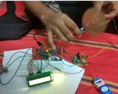
[image:5.595.323.533.86.211.2]This circuit has a DC motor attached with the cardboard disc with a slit. We have used IR sensor module and placed it in front of the disc attached to the DC motor. The IR sensor detects the change in intercepted Infrared values while the disc is rotating along with the dc motor and ultimately results in to an estimation (precise after each iteration) of the current RPM of the DC motor. This RPM value is also fed to themicrocontroller as a feedback. Everytime the loop is run in the Arduino code the error reduces, that is the difference between the set speed actual speed decreases until it reaches saturation where the desired speed cannot get any closer to the set speed.
Fig. 16:- Hardware Circuit to control the DC Motor
Fig. 17:- Set RPM and Actual RPM displayed on the LCD.
IV. RESULTS
The results of our experiment are tabulated in Table II where obtained speeds and the desired speeds are tabulated for each technique separately. It is observed from Table II that upon using Hardware the obtained speed is 150 rotations per minute. The software simulations however provide better results. On implementing PID Controller using Simulink the obtained speed is 100 Rotations per minute. PWM Hysteresis gives us a speed of 195 Rotations per minute.
TABLE II
EXPERIMENTAL RESULTS
Technique Used Desired Speed (RPM)
Actual Speed (RPM)
Hardware 200 150
PID Controller 200 100
PWM Hysteresis 200 195
V. CONCLUSION
The review of many research papers as well as tremendous software (MATLAB, SIMULINK) and hardware analysis has been carried out in the area of speed control of dc motor to investigate and find out current challenges and scope of work in the area. After the review, the main issue was found that the speed control of dc motor is a typical task. The solutionapproaches under particular research paper were studied in depth and were analyzed on the basis of various findings, which helped to understand the strengths and weaknesses of the solution approaches. Out of these issues, the study and implementation of speed control method of dc motor via PID controller, PWM hysteresis as well as using Arduino and IR sensor based hardware protocol. Our paper concludes with the comparison of error analysis of the speed measured using these various techniques. The paper thus brings to you the shortcomings of the various methods of speed control. Table analysis of software, hardware implementations shows PWM hysteresis as an ideal method for controlling speed in dc motors with
[image:5.595.55.294.485.675.2]The comparison also brings to light the various disadvantages of the implemented methods and how they can be rectified.
In the table by comparing the difference between the desired RPM and set RPM, it is clearly seen that the mostefficient way to control the speed is using PWM Hysteresis since the deviation from the desired speed is the least in this particular method. When IR sensor and Arduino are used to control speed,the deviation comes out to be 50 RPM. So it could be considered the next choice. When PID controller is used the difference is nearly 100 RPM. So this would be the least favorable method. Our further research could be based on implementing PWM Hysteresis for hardware applications so that we could apply the best technique to control DC motor speed.
REFERENCES
1. Hang Wu; Weihua Su; Zhiguo Liu, "PID controllers: Design and tuning methods," Industrial Electronics and Applications (ICIEA), 2014 IEEE 9th Conference on ,vol.,no.,pp.808,813,9-11 June 2014. 2. AdityaPratap Singh, “Speed Control of DC Motor PID Controller
Based on Mat lab” International Conference on Recent Trends in Applied Sciences with Engineering Applications, Vol.4, No.6, 2013. 3. Dahl, Nicolai Jerram; Iversen, NielsElkjær; Knott, Arnold; Andersen,
Michael A. E. “Comparision of Simple Self-Oscillating PWM Modulators”. Published in: Proceedings of the 140th Audio Engineering Convention Convention.
4. S. Poulsen, M. A. E. Andersed 0rsted. “Self Oscillating PWM Modulators ,A Topological Comparision”, DTU Automation, Technical University of Denmark Eiehovej, Building 325, 2800 Lyngby, Denmark.
AUTHOR PROFILE
Hardik S Jainis a student in the
department of Communication
Engineering, School of Electronics Engineering at Vellore Institute of Technology (VIT), Vellore, Tamilnadu, India. He did his schooling in Maharishi Vidya Mandir School, Chennai, Tamilnadu. He was awarded with various prizes in School for his excellent performance in academics. He was also awarded with prize for securing 3rd place in a Mathematics competition held in Pondicherry, India. He was a former member of the IEEE-IAS chapter of VIT and has organized events in „Gravitas‟ (technical fest of VIT) for the chapter. He was also the Program Representative for ECE branch. He was a coordinator in „Riviera 2019‟ (Cultural Fest) of VIT. His main interest is in Embedded Systems, Control Systems, and Microcontrollers and has done many projects in it. His other interests lie in Computer Networking and Communications.
AkshatPalakis a student in the
department of Communication
Engineering, School of Electronics Engineering at Vellore Institute of Technology (VIT), Vellore, Tamilnadu, India. He did his schooling in St.Xavier‟s School, Bokaro Steel City, Jharkhand. He was the president of science club
in his school. He was awarded with
Dr.BhimraoRamjiAmbekar memorial prize in class 12th for his excellent performance in studies and sports. He was the
former member of The Electronics club of VIT. He was the organizer of „The Sensors Workshop‟ held at the Gravitas (Techincal Fest) of VIT. His main interest lies in Basic & Power Electronics ,Control Systems & Computer Communications and has done many projects in it.
SandeshAgrawal is the student in the department of Communication Engineering, School of Electronics Engineering at Vellore Institute of Technology (VIT), Vellore, Tamilnadu, India. He did his schooling in St Mary‟s school, Harda city, Madhya Pradesh. He was the House representative in his school. He worked as Coordinator in VIT Riviera 2019. His main interest lies in Computer Networking, Signals and Systems ,Control Systems & VLSI system design. He has done many projects like Smart Restaurant Ordering System and Smart Helmet.
KrishnamTibrewal is the student in the
department of Communication
Engineering, School of Electronics Engineering at Vellore Institute of Technology (VIT), Vellore, Tamilnadu, India. He did his schooling in Noble International School, Bhilwara city, Rajasthan. He was the president of maths club in his school.. He was the former member of IEEE-PES of VIT. He is the Programme Representative of ECE Branch . His main interest lies in Signals and Systems ,Control Systems & VLSI sytem design and has done many projects in it.