International Journal of Innovative Technology and Exploring Engineering (IJITEE) ISSN: 2278-3075, Volume-9 Issue-1, November 2019
Abstract: The objective of the study is to investigate the performance improvement in a split air conditioning system using evaporative cooling pads at ODU (outdoor unit) and to determine optimum thickness and material of the cooling pad. For this purpose experiments were conducted on 0.8 TR capacity split air conditioner charged with refrigerant R-22. For comparison experiments were performed with and without evaporative cooling pad. The effect of the different cooling pad material and thickness on the overall performance of split air conditioner is experimentally found by measuring cooling capacity and the power consumption of the system including water circulation pump. From the experimental work it is found that the cellulose cooling pad gives the best results among the selected materials. Split air conditioner coupled with cellulose cooling pad of 100 mm thickness at ODU results in to 13.8% increase in overall COP, 9.5 % reduction in power consumption and 5.1 % increase in cooling capacity at 35°C DBT and 32% relative humidity outdoor air condition.
Keywords: Evaporative cooling pad, COP, Split AC
I. INTRODUCTION
E
nergy is a very significant factor in driving durable economic growth and development of any country. The decrease of energy consumption through efficient energy use or by reducing the consumption of energy sources is a goal in all engineering fields. Air conditioning systems are nowadays commonly used in buildings due to the improvement of both qualities of life and comfort levels in the society. Lombard et al. [1] presented review on building energy consumption and according to that HVAC system consumes about 10% of total energy consumption in developed countries. Since huge numbers of air conditioners are in use, any considerable improvement in the performance of the same will have a huge effect on the power consumption. In summer when the temperature is so high, the power consumption of air conditioners increases abruptly and as a consequence, their performance decreases. This problem arises as the compressor has to produce a higher pressure ratio than its design condition.Refrigeration cycle includes four essential fundamental processes, compression of refrigerant by the compressor, condensation of refrigerant in the condenser,
Revised Manuscript Received on November 05, 2019.
* Correspondence Author
Balkrushna Shah, Mechanical Engineering Department, Nirma University, Ahmedabad, Gujarat, India. Email: [email protected]
Shivam Dwivedi, Sr.Executive Engineer, Johnson Control Hitachi Air Conditioning India Limited, Kadi, Gujarat, India
Ath Singhal, Mechanical Engineering Department, Nirma University, Ahmedabad, Gujarat, India.
Throttling of refrigerant in the expansion device and evaporation of refrigerant in the evaporator by absorbing energy from cooling space. In this cycle, refrigerant rejects heat to the cooling medium (here atmospheric air) inside the condenser and to accomplish this process condenser pressure and temperature must be higher than temperature and pressure of the cooling medium. Due to this compressor discharge pressure completely depend on surrounding temperature and its corresponding saturation pressure. So, in extreme summer conditions, compressor pressure ratio increases and it adversely affects compressor performance. One of the possible methods to limit the power consumption of air conditioner in dry and hot summer is a reduction in the pressure ratio by decreasing the condenser inlet temperature, and it is accomplished by placing a cooling pad just before the inlet of the condenser or outdoor unit.
The process of reducing inlet air temperature with help of evaporation of water over cooling medium is called evaporative cooling, which is used in the modified system. Evaporation is the phase transformation process of surface molecules by absorbing their required latent heat from neighbor particles. When phase changing particles steal energy from neighbors, the neighbor's energy content decrease, and which lead to a fall in their temperature. Here hot and dry atmospheric air is passed through a cooling medium pad (over which water is being continuously circulating) and when these air and water comes in contact with each other, water gets evaporated into the air. This evaporation phenomenon is fulfilled by absorption of energy from the air and hence the temperature of air decreases and due to water diffusion into it, its humidity increases. Here ideally air loses energy in the form of sensible heat but gains back energy in the form of latent heat of vaporization of water. This process is considered adiabatic by assuming there is no heat transfer between system and surrounding and only heat transfer occurring between air and water. Hence evaporative cooling of air is considered adiabatic. Evaporative cooling is a green method which does not involve any greenhouse emission and global warming.
Some of the past research work on the evaporative cooling of air-conditioners includes that by Youbi-Idrissi [2] who proposed a semi-local numerical model on the sprayed air-cooled condenser and applied this system to a refrigeration and air conditioning system of a steel plant. He observed that COP raise by 55% than a conventional system. Yang and Chan[3] investigated air-cooled chiller with mist pre-cooling experimentally. They observed that there was a 9.4 K drop in DBT of intake air and the condensing temperature drop by up to 7.2
K. According to them with mist cooling arrangement COP
Energy Saving in Split Air Conditioner using
Evaporative Cooling Pad at the ODU
could be improved up to 18.6%. Islamand K.A Janhangeer [4] studied the performance of an air-conditioning unit with evaporative cooled condenser coil experimentally and numerically. They came up with 28% higher COP, compared to the conventional system. Ebrahim Hajidavalloo [5] experimentally studied window air conditioner with cooling media pad installed at condenser. He observed that power consumption decrease up to 16% and the COP increase by 55%. E. Hadidavalloo and H Eghtedari[6] further performed an experiment on split air-conditioner with an evaporative cooled condenser. They show that the power consumption can be reduced up to 20% and the COP can be improved by around 50%. Tianwei Wang and Chenguang Sheng[7] compared the effect of the evaporative cooled condenser with a conventional air-cooled condenser (using residential sized condenser and evaporator). Their results showed that the saturation temperature drop through the condenser increased from 2.4 °C to 6.6 °C, which lead to increase of COP from 6.1% to 18%. P. Martinez[8] experimented on variable thickness cooling pad integrated with split air conditioner. Results show the reduction of 11.4% in compressor power consumption, the increment of 1.8% in the cooling capacity and the overall COP increment of 10.6% for 100 mm thick pad (out of 50mm, 100mm, 150mm).
Harby and et al. [9] reviewed used of evaporative condenser in residential cooling systems. According to them power consumption in cooling system with air cooled condenser can be reduced up to 58% and the COP can be improved by about 113.4%. Yu and Chan [10] found that mist pre-cooling results in to improvement in COP of chiller irrespective of chiller operated under HPC or CTC in hot and dry regions where humidity is below 50%. They have also carried out annual energy analysis and found that CTC with mist pre-cooling could achieve a 19.84% reduction in the annual electricity consumption of the system. Ibrahim et al.[11] shown that pre-cooling the air by about 4 °C before entering the condenser lowers the compressor discharge pressure. The decrease in the discharge pressure resulted in the decrease in compressor power consumption by 6.1% and the cooling effect of the system is enhanced. The combined effect of the increase in the cooling effect and decrease in compressor power resulted in an increase in the coefficient of performance (COP) by about 21.4% and second law efficiency of the system by about 20.5%.
From the literature review it is found that precooling of air at the inlet of condenser in split air conditioner results into reduction in electricity consumption, however effect of various cooling pad material haven not been considered so far. The main objective of present work is to compare the performance of split air conditioner without evaporative cooling pad and with evaporative cooling pad of different cooling pad material and thickness at ODU.
II. EXPERIMENTALAPPARATUS
For conducting the experiment split air conditioner test rig as shown in Fig. 1 have been used, which consist of conventional split air conditioner with necessary tapings for temperature and pressure measurement as shown in Fig. 2.
The Split air conditioning is fixed in a rigid angle frame, with its indoor and outdoor units separated by a control panel.
These are connected by intermediate piping. The required pressure and temperature tapping are drawn for measurement of pressures and temperatures at salient points. Pressure tapping is provided at compressor inlet to give evaporator pressure and after compression to give condenser pressure. Temperature tapping is provided at after-evaporator, after compression, after condensation and after expansion device to give the temperature of the refrigerant at these salient points. The energy meter is provided for recording compressor energy consumption. A sling psycho-meter is provided for measurement of inlet and outlet Dry-bulb & Wet bulb temperature. An anemometer is used to measure the flow rate of air at the inlet and outlet of the indoor and outdoor unit. The Air Conditioning trainer works on VCR cycle using R 22 (HCFC-22) as a refrigerant. Rated cooling capacity of the test setup is 0.8 ton. Its rated maximum and minimum pressure limits are 2.7 Mpa and 0.7 Mpa.
The cooling medium is a porous material pad fitted inside the steel frame having an arrangement for water basin at the top from where water is poured. The top basin is having holes throughout to help the uniform water distribution over the cooling medium. A water collecting basin is used just below the steel frame which acts as a sump. A water pump is used for continuous circulation of water in this circuit from the bottom sump to the top basin. There is a gap between the indoor unit and outdoor unit, and in this gap, a water collecting tank is placed, above which a cooling pad is mounted. A water pump is placed into the water sump, which maintains the continuous flow over the pad. Now when atmospheric air passes through this pad it gets cooled due to evaporative cooling.
Fig.1: Experimental setup
The experimental setup is shown in Fig.1 and a schematic diagram of this setup shown in Fig. 2, which provide a clear view of the flow of air and refrigerant through different component and in which sequence these fluids will pass through these components. In this diagram right portion shows the VCR cycle in which refrigerant passes through the evaporator, compressor, condenser and expansion valve in a sequence. Left portion shows air flow through cooling pad then through condenser coil and goes to atmosphere. A. Experimental Procedure
Experimental procedure followed are as below: The water collecting sump
International Journal of Innovative Technology and Exploring Engineering (IJITEE) ISSN: 2278-3075, Volume-9 Issue-1, November 2019
Turn on the main power supply to spilt air conditioner. Run the set up for 30 minutes so that all parameters reaches
to steady state.
After 30 minutes record the following parameters: Compressor suction and discharge pressure.
The temperature of refrigerant after evaporation, after compression, after condensation and after expansion. DBT and WBT of air going in and out of the IDU(Indoor
Unit) as well as ODU(Outdoor Unit).
The temperature of air between the cooling pad and ODU. The average velocity of air at the outlet of the IDU and
ODU.
[image:3.595.61.279.226.376.2] Power consumption from energy meter reading.
Fig. 2: Schematic diagram of the experimental setup
III. CALCULATIONS Evaporative Cooling Pad Efficiency
Cooling pad efficiency is a performance parameter for cooling pad used that how efficiently it is doing its job. It is defined as the ratio of the actual drop in temperature of air across the cooling pad to the maximum possible drop in temperature.
di do
di wi
T T Cooling efficiency =
T T
(1) Where Tdi = DBT at inlet of cooling pad, Twi = WBT at inlet of cooling pad, Tdo = DBT at outlet of cooling pad Theoretical Coefficient of Performance (COP)
COP is the performance analysis tool for any refrigeration and air conditioning cycle. COP is defined as the ratio of refrigerating effect to the work input. Theoretical COP is calculated by measuring enthalpy of refrigerants corresponding to its temperature at various salient points from the property table of R-22.
Mathematically it is represented as,
𝐶𝑂𝑃 =
𝑅𝑒𝑓𝑟𝑖𝑔𝑒𝑟𝑎𝑡𝑖𝑛𝑔 𝑒𝑓𝑓𝑒𝑐𝑡𝑊𝑜𝑟𝑘 𝑖𝑛𝑝𝑢𝑡
=
1−4
2−1 (2)
Actual Coefficient of Performance (COP)
Here the energy meter gave the total power consumed. While the actual refrigerating effect is obtained by calculating the drop in enthalpy of air at the evaporator inlet (hai) and the evaporator outlet (hao).
Qc = ma (hai - hao) (3) Where, ma = ρaoAoVao
Actual COP = Qc / Ptotal (4)
Where Qc = Cooling capacity, Ptotal = Total power consumption
IV. RESULTANDDISCUSSION
From the experiment observations on various types of cooling pad material at 150 mm thickness cooling pad efficiency have been calculated using equation (1). With this calculations, get the graph shown in Fig. 3. This graph shows that the efficiency of the cellulose pad is higher than other pad material. Further testing have been carried out on cellulose cooling pad with different thickness and then experiments performed on it. Cooling pad efficiency calculated from this experiments is shown in Fig. 3. From this Fig. we can see that cooling pad efficiency increases with thickness of cooling pad.
Fig. 3: Comparisons of cooling pad materials and thickness versus cooling pad efficiency
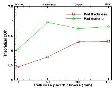
[image:3.595.321.525.244.413.2]The theoretical COP of Split Air Conditioner find out from the equation (2). Therefore obtained the graph given in Fig. 4. This graph shown that cellulose cooling pad is more efficient compared to other cooling pad. The graph in Fig. 4 shows that increase in the theoretical COP with cellulose cooling pad thickness. It also shows that slop of theoretical COP increases in 50mm and 100mm thickness cooling pad then this slop is decreasing.
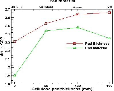
[image:3.595.323.511.555.705.2]The actual COP of Split Air Conditioner find out from the equation (3) and results obtained are shown in Fig. 5. This Fig. shows that cellulose cooling pad’s actual COP is more compared to other cooling pad. The Fig. 5 also shows that the actual COP increases with cellulose cooling pad thickness.
Fig. 5: Actual COP of system vs cooling pad material and cellulose cooling pad thickness
[image:4.595.62.261.135.294.2]In the various cooling pad materials, compressor suction and discharge pressure has been shown in Fig. 6. This graph shows that the compressor discharge pressure and compressor suction pressure in cellulose cooling pad material is low compared to other cooling pad material. Difference between compressor discharge pressure and suction pressure is less in cellulose cooling pad material so work required to run the compressor is less in cellulose cooling pad material. In the various cellulose pad thickness, compressor suction and discharge pressure has been shown in Fig. 6. The graph shows that compressor suction and discharge pressure decreases with increases cellulose cooling pad thickness. Difference between compressor discharge pressure and suction pressure is also decreases when increases the cellulose cooling pad thickness so work required to run the compressor is decrease with increase cellulose cooling pad thickness.
Fig. 6: Compressor suction and discharge pressure vs pad material and cellulose pad thickness
Evaporator inlet (T4) and outlet (T1) temperature and condenser inlet (T2) and outlet (T3) temperature at various cooling pad material in shown in Fig. 7. Here condenser discharge temperature (T3) is less in cellulose cooling pad
compared to other cooling pad material. In the various cellulose pad thickness, this all temperature has been shown in Fig. 7. It shows that condenser discharged temperature decreases with increase in the cellulose pad thickness.
Fig. 7: Various VCR cycle temperature vs pad material and cellulose pad thickness
V.
C
ONCLUSIONSFollowing conclusions are obtained from the above experimentation on split air conditioner having an evaporative cooling pad just before the outdoor unit to precool the atmospheric air entering the condenser unit:
Experiment results shows that the cellulose cooling pad give the best performance out of grass and PVC pad material selected.
Among cellulose cooling pad of varying thickness, 100 mm thickness cellulose cooling pad give the highest COP improvement compare to 50 mm and 150 mm thickness cellulose cooling pad.
It is found that for 100 mm cellulose cooling pad about 12% drop in compressor discharge pressure, 13.8% enhancement in actual COP, 9.5 % reduction in power consumption and 5.1 % increase in cooling capacity take place at 35°C DBT and 32% relative humidity outdoor air condition.
ACKNOWLEDGMENT
This research work have been funded by Nirma University. The authors are grateful to Management Nirma University for their financial support. The authors also like to acknowledge Head, Mechanical Engineering Department and Director, Institute of Technology, Nirma University for their support in the present project work.
REFERENCES
[image:4.595.64.279.531.704.2]International Journal of Innovative Technology and Exploring Engineering (IJITEE) ISSN: 2278-3075, Volume-9 Issue-1, November 2019
2. M. Youbi-Idrissi, H. Macchi-Tejeda, L. Fournaison, and J. Guilpart, “Numerical model of sprayed air cooled condenser coupled to refrigerating system,” Energy Convers. Manag., vol. 48, no. 7, pp. 1943–1951, Jul. 2007.
3. J. Yang, K. T. Chan, X. Wu, X. Yang, and H. Zhang, “Performance enhancement of air-cooled chillers with water mist: Experimental and analytical investigation,” Appl. Therm. Eng., vol. 40, pp. 114–120, Jul. 2012.
4. M. R. Islam, K. A. Jahangeer, and K. J. Chua, “Experimental and numerical study of an evaporatively-cooled condenser of air-conditioning systems,” Energy, vol. 87, pp. 390–399, Jul. 2015. 5. E. Hajidavalloo, “Application of evaporative cooling on the condenser
of window-air-conditioner,” Appl. Therm. Eng., vol. 27, no. 11–12, pp. 1937–1943, Aug. 2007.
6. E. Hajidavalloo and H. Eghtedari, “Performance improvement of air-cooled refrigeration system by using evaporatively cooled air condenser,” Int. J. Refrig., vol. 33, no. 5, pp. 982–988, Aug. 2010. 7. T. Wang, C. Sheng, and A. G. A. Nnanna, “Experimental investigation
of air conditioning system using evaporative cooling condenser,” Energy Build., vol. 81, pp. 435–443, Oct. 2014.
8. P. Martínez, J. Ruiz, C. G. Cutillas, P. J. Martínez, A. S. Kaiser, and M. Lucas, “Experimental study on energy performance of a split air-conditioner by using variable thickness evaporative cooling pads coupled to the condenser,” Appl. Therm. Eng., vol. 105, pp. 1041–1050, Jul. 2016.
9. K. Harby, D. R. Gebaly, N. S. Koura, and M. S. Hassan, “Performance improvement of vapor compression cooling systems using evaporative condenser: An overview,” Renew. Sustain. Energy Rev., vol. 58, pp. 347–360, May 2016.
10. F. W. Yu and K. T. Chan, “Simulation and electricity savings estimation of air-cooled centrifugal chiller system with mist pre-cooling,” Appl. Ener
11. N. I. Ibrahim, A. A. Al-Farayedhi, and P. Gandhidasan, “Experimental investigation of a vapor compression system with condenser air pre-cooling by condensate,” Appl. Therm. Eng., vol. 110, pp. 1255–1263, Jan. 2017.
AUTHORS PROFILE
Prof. Balkrushna Shah is currently working as Assistant Professor in Mechanical Engineering Department, Institute of Technology, Nirma University. He has published papers in more than 22 national and international conferences in the area of refrigeration and air conditioning, renewable energy and computational fluid dynamics. He has guided more than 15 PG dissertations. Currently he is pursuing PhD in Boiling Heat Transfer. His Interests include boiling heat transfer, refrigeration and air conditioning.
Shivam Dwivedi is Sr. Executive Engineer at Johnson Control Hitachi Air Conditioning Limited, Kadi, Gujarat. He has done his M.Tech. in Thermal Engineering from Institute of Technology, Nirma Unviersity. He is currently involved in research work at Johnson Control Hitachi Psychrometry Lab.