Abstract: In this research work the performance of closed loop speed control of Indirect Field Oriented controlled Induction motor using Sliding Mode Controller is described. The phenomenon of chattering of the control signal, which is the major disadvantage of Sliding Mode Control is overcome by applying Exponential Reaching Law. In the proposed method an exponential function is used as the sliding variable which dynamically adapts with the variations of the controlled system. The mathematical modeling of complete system is done and the simulated results are compared with conventional sliding mode controller and classical PID controller. The simulation results verify the superior performance and chattering reduction by employing Sliding Mode Controller with Exponential Reaching Law..
Index Terms: Sliding Mode Control; Chattering; Exponential Reaching Law; PID controller.
I. INTRODUCTION
In the last few decades the classical PID controllers were widely used for the control of induction motor drives [1] due to its simplicity and satisfactory performance. But the behavior of the PID controller is still influenced by the uncertainties which can happen due to unpredictable parameter variations, external load disturbances and nonlinear dynamics. Therefore many studies such as adaptive control, Variable Structure control, artificial intelligence using fuzzy logic and neural control etc [2, 3, 4] have been implemented to increase the robustness and precision of Induction motor in the presence of uncertainties. Nowadays, the variable structure control using sliding mode controller has gained more attention regarding the control of Induction motor drives [5]. The most important feature of sliding mode control (SMC) is its robustness. The only limitation of SMC is the phenomena called chattering. It is the high frequency oscillations of the controller output due to the high speed switching required for the implementation of the sliding mode. As it involves high control activity and increase in power consumption, in practical applications chattering is highly undesirable. Recently different methods have been suggested to suppress the effect of chattering such as boundary layer method, using higher order SMC, adaptive algorithms etc [6, 7].
Revised Manuscript Received on June 05, 2019
Jisha L K, Research Scholar, Dept of Electrical &Electronics Engineering, HKBK College of Engineering, Bangalore, India.
A A Powly Thomas, Principal, Gopalan College of Engineering & Management, Bangalore, India.
Suresh Srivastava, O/o Director General – Aeronautics, DRDO, Bangalore, India.
In this research work a sliding mode control strategy with exponential reaching law is considered. The proposed method uses an exponential term in the expression for sliding surface S. The exponential function smoothly adapts with the variation of S. The validity of the developed system has demonstrated through simulation. The results obtained have confirmed the superior performance by using exponential reaching law in the aspects of fast and good dynamic response and less control effort.
II. MATHEMATICAL MODEL OF VECTOR
CONTROLLED INDUCTION MOTOR
The state equations of vector controlled Induction motor is described below [1]. The state variables selected are ids, iqs,
ψdr, ψqr.
(1)
Where ids , iqs are direct and quadrature axis components of
stator currents, ψdr , ψqr are direct and quadrature axis
components of rotor flux. Rsand Rr are stator and rotor
resistance respectively.
Ls, Lrand Lm are stator, rotor and mutual inductances.
is the leakage coefficient of flux.
is the rotor time constant.
In the field oriented control, for decoupling of torque and flux, should be oriented in the direction of flux and should be orthogonal to it.
Speed Control of Vector Controlled Induction
motor by Sliding Mode Control with
Exponential Reaching Law
This condition is met if = 0, , ψdr=
Then the above equations are simplified to
(2)
Te (3) Where,
Where is the command rotor flux
From (2),
(4) and = ʃ dt
III. SLIDING MODE CONTROLLER AND
EXPONENTIAL REACHING LAW
The sliding mode control is a nonlinear control strategy. The synthesis of SMC entails two stages. The first stage is the selection of suitable sliding surface S(t) and second stage is the design of control input u(t). The S(t) is chosen as ,
S(t) = λe + ė (5) Where , is the tracking error (6) and are the mechanical speed of induction motor and its reference speed respectively, λ is a positive constant. When the trajectory approaches the sliding surface, tracking error e converges to zero.
The second stage is to design the control law which directs the system trajectories towards the sliding manifold. It is possible if the condition,
S(t). , Ɐ t (7)
is met. The above condition is called reaching law. In order to satisfy the above condition, in conventional SMC, is typically chosen as,
Ɐ (8) The term – will drive the system trajectory towards the sliding surface rapidly. Therefore higher value of will reduce the time of reaching mode. But higher value of induces more chattering.
For Exponential Reaching Law [8] the is chosen as Ɐ (9)
The term –KS contributes to the exponential function as the solution of is an exponential term which is of the form S = S(0) .
The electro-magnetic torque (Te) equation of the Induction
motor is given by
= J + B + (10) is the external load applied to the Induction motor.
From (3) and (10),
J + B + = (11) As per (2) u(t) which controls the rotor speed.
Differentiating (5),
(12)
Where ė = - , ё = (13) , are zero as the reference speed is considered as constant.
Using (9),(10),(12) and (13), iqs=
(14)
It is seen that the control signal u = has two parts, equivalent control and discontinuous control .
ueq
udisc
The discontinuous control which has signum function (sign (.)) induces chattering [9,10]
As time tends to infinity speed tracking error, tends to zero.
Proof:
Let the Lyapunov candidate function is V(t) = S(t)2 Substituting (12)
= S(t) [ ] = S(t) (t)
Substituting (13)
= S(t) [ - ]
Using equation (9)
= S(t)[ ] = S(t) (t)
As per equation (7) which shows that function is negative definite, V(t) tends to infinity as S(t) tends to infinity. Therefore the equilibrium at the origin is globally asymptotically stable and S(t) tends to zero as time approaches infinity[11,12]
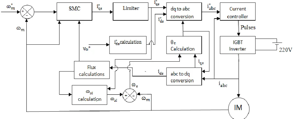
Figure1. Block diagram representation of the system with SMC Figure 1 shows the block diagram representation of the
complete system described. As shown in fig.1, the power circuit consists of DC supply of 220V and IGBT two level inverter.The speed control loop generates the torque component of current . The flux component of current for the desired rotor flux is generated. The conversion of three phase stationary abc coordinates to two phase rotational dq system is done using Clarke’s and Park’s transformations. The current controller used is Hysteresis current control which takes the three phase reference and measured currents as input. Both the currents are compared and generate six PWM pulses, which is input to the IGBT inverter. The slip frequency is generated from in the feedforward manner. Signal is added with speed signal to generate the frequency signal The signal θe is
obtained by integrating
IV. ILLUSTRATIVE CASE STUDY
The simulation of indirect field orient controlled induction motor is done using a 1HP (746W) three phase squirrel cage induction motor. The simulation is carried out with PID controller, conventional SMC and SMC with ERL. For simulation MATLAB (R2014a) /SIMULINK is used. The Induction motor parameters used for case study are 3A, 220V, 50Hz, 4Pole, Rs = 6.37Ω, Rr = 4.3 Ω, Lm = 0.24H, Ls =
Lr = 0.26H, J = 0.0088Kg/m2. The PID controller is designed
with Kp = 45, Ki = 0.1 and Kd = 0.5. For the design of conventional SMC, λ = 100 and ε = 400 are used. For SMC with ERL, λ = 100, ε = 300 and K =1500 are used. The reference speed of 120 rad/sec is selected.
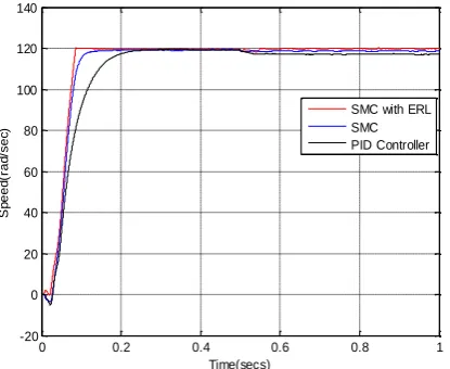
[image:3.595.57.538.66.259.2]
Figure 2. Speed - Time response of PID, SMC and SMC with ERL without applying external load.
Table 1
Performance comparison of different controllers
Controller Delay time Rise time
Settling time
description in secs in secs in secs
0.02 0.08 0.08
SMC with ERL
0.05 0.09 0.09
SMC
0.05 0.2 0.25
PID
0 0.2 0.4 0.6 0.8 1
-20 0 20 40 60 80 100 120 140
Time(secs)
S
pe
e
d(
ra
d/
se
c)
[image:3.595.321.556.305.467.2]Figure 3. Speed - Time response of different ontrollers by applying external load of 6Nm after 0.5 secs.
Figure 4. Speed - Time response of different controllers with Sudden change in speed at 0.5 secs.
Figure 5. Control signal iqs with conventional Sliding Mode Controller.
Figure 6. Control signal iqs of Sliding Mode Controller with ERL
Figure 7. Sliding function of SMC and SMC with ERL
[image:4.595.63.270.288.453.2]
Figure 8 Speed – time response of SMC and SMC with ERL for 5% variation in rotor resistance
0 0.2 0.4 0.6 0.8 1
-20 0 20 40 60 80 100 120 140
Time(secs)
S
p
e
e
d
(r
a
d
/se
c)
SMC with ERL SMC PID Controller
0 0.2 0.4 0.6 0.8 1
-20 0 20 40 60 80 100 120 140 160
Time(sec)
S
p
e
e
d
(r
a
d
/se
c)
SMC SMC with ERL PID
0 0.2 0.4 0.6 0.8 1
-50 -40 -30 -20 -10 0 10 20 30 40 50
Time(secs)
iq
s
(
A
)
0 0.2 0.4 0.6 0.8 1
-50 -40 -30 -20 -10 0 10 20 30 40 50
Time(secs)
iq
s
(A
)
0 0.2 0.4 0.6 0.8 1
-14000 -12000 -10000 -8000 -6000 -4000 -2000 0 2000
Time(secs)
S
li
d
in
g
f
u
n
ct
io
n
,S
(t
) SMC
SMC with ERL
0 0.2 0.4 0.6 0.8 1
-20 0 20 40 60 80 100 120 140
Time(secs)
S
p
e
e
d
(r
a
d
/se
c
)
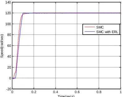
[image:4.595.65.272.513.692.2]Figure 9 Speed – time response of SMC and SMC with ERL for 5% variation in rotor inductance
Figure 10 Speed – time response of SMC and SMC with ERL when continuously increasing load of 0 to 6Nm is
applied from t=0 onwards.
Figure 2 shows the Speed - Time response of PID, SMC and SMC with ERL without applying external load. Table 1 shows the performance comparison of three controllers. It is seen that the rise time of PID controller is more compared to that of sliding mode controllers. Figure 3 shows the performance of different controllers in the presence of sudden external load of 6Nm applied after 0.5 secs. It is seen that SMC gives a robust control if there is sudden disturbance in the load. But for PID controller speed is suddenly reduced when sudden load is applied. In SMC with ERL approach apart from the robust control the transient behavior of the system is also improved. Figure 4 shows the Speed – Time response of PID, SMC and SMC with ERL when a step change in speed is applied after 0.5 secs. The reference speed is changed from 100rad/sec to 140rad/sec. The figure shows that the performance of SMC with ERL is superior than other controllers.
Figure 5 and 6 show the control input iqs with conventional
SMC and SMC with ERL respectively. The chattering of control signal is reduced when ERL is implemented compared to conventional SMC. Thereby it reduces the control effort and the power consumption of the system. Figure 7 shows the sliding function with SMC and SMC with ERL. It is observed that chattering is more in the sliding function of conventional SMC. The reaching time for SMC with ERL is slightly less than that of conventional SMC. Figure 8 shows the response of conventional SMC and SMC
with ERL in the presence of parameter variations. The rotor resistance is varied by 5%.The figure shows that robustness is preserved in both the methods. Figure 9 shows the response of conventional SMC and SMC with ERL in the presence of parameter variations. The rotor inductance is varied by 5%.and it is seen that both the approaches are showing constant response. Figure 10 shows the performance of conventional SMC and SMC with ERL when a continuously increasing load is applied. The load varies from 0 to 6Nm with constant slope.
V. CONCLUSION
In this paper speed control for vector controlled induction motor is presented. The sliding mode controller with exponential reaching law is implemented for robust control. The mathematical model of indirect field orient controlled Induction motor with speed controller is described and numerical simulation is done. From the simulation results it is seen that performance of sliding mode control with exponential reaching law is superior to that of conventional PID controller and conventional sliding mode controller in the presence of uncertainties like parameter variations and load disturbances. The chattering phenomenon of sliding mode control is reduced by incorporating exponential reaching law.
REFERENCES
1. Bimal.K.Bose, “Modern Power Electronics and AC Drives”, Prentice Hall of India Private Limited, 2008.
2. U.I.Utkin, J. Guldner, Jingxin Shi”Sliding mode control in Electro Mechanical Systems”,Taylor and Fancis group Second Edition , 2009. 3. Benchaib, C. Edwards, “ Induction motor control using nonlinear
Sliding mode theory”, 1999 Europeon Control Conference (ECC) 31st August – 3rd September, 1999, Karlsruhe, Germany.
4. Oscar Barambones, Patxi Alkorta, , “Sliding Mode Position Control for Real Time Control of Induction Motor”, International Journal of Innovative Computing, Information and Control, Vol. 9 July 2013. 5. Dramane Traore, F, Plestan, A. Glumineau, “High-Order Sliding –
Mode Controller and adaptive Interconnected Observer”, IEEE transactions on industrial Electronics, Vol 55, No 11, November 2008
6. Roman Costa – Castello, Niliana carrera, Sebastian Dormido, Enric Fossas, “Teaching, Analysing, Designing and interactively simulating SMC”, IEEE Access, april 18, 2018.
7. Huan Liu, Han Cui, “Study on a Sliding Mode Variable Structure
Vector Control of Induction Motor Drives”, Proceedings of the 10th
World Congress on Intelligent Control and Automation, July 6-8, 2012, Beijing, China.
8. Charles Fallaha, Maarouf Saad, Hadi Y. Kanaan, and Kamal Al-Haddad, “Sliding Mode Robot control with Exponential Reaching Law”, IEEE transactions on industrial electronics, Vol., no.58 , March
2011
9. Mohammad H. Rahman, Maarouf Saad, Jean-P Kenné, P. S. Archambault “Control of an exoskeleton robot arm with sliding mode exponential reaching law”, International Journal of Control, Automation and Systems, Vol. 11, February 2013, PP 92-104. 10. Andrzej Bartoszewicz, Pawel Latosinski,” Reaching law for DSMC
systems with relative degree 2 switching variable”, International Journal of Control,Vol.90, August 2016, PP 1626-1638.
11. Utkin-80, “Sliding Mode Control and Observation” Wiely Online Library,Volume 23, Issue 3, February 2019.
12. Lina Wang, Haihuai Zhang, “Sliding Mode Control with Adaptive Fuzzy Compensation for Uncertain Nonlinear System”, Mathematical Problems in Engineering,Hindawi, Volume 2018, December 2018.
0 0.2 0.4 0.6 0.8 1
-20 0 20 40 60 80 100 120 140
Time(secs)
S
p
e
e
d
(r
a
d
/se
c)
SMC SMC with ERL
0 0.2 0.4 0.6 0.8 1
-20 0 20 40 60 80 100 120 140
Time(secs)
S
p
e
e
d
(r
a
d
/se
cs)