City, University of London Institutional Repository
Citation
:
Tanda, G. (1996). Application of optical methods to the study of convective heat transfer in rib-roughened channels. (Unpublished Doctoral thesis, The City University of London)This is the accepted version of the paper.
This version of the publication may differ from the final published
version.
Permanent repository link:
http://openaccess.city.ac.uk/19300/Link to published version
:
Copyright and reuse:
City Research Online aims to make research
outputs of City, University of London available to a wider audience.
Copyright and Moral Rights remain with the author(s) and/or copyright
holders. URLs from City Research Online may be freely distributed and
linked to.
DOCTOR
OF
PHILOSOPHY
Giovanni
TANDA
APPLICATION OF OPTICAL METHODS TO THE STUDY OF CONVECTIVE HEAT TRANSFER IN RIB-ROUGHENED CHANNELS
by
Giovanni Tanda
A Thesis submitted to The City University of London
for the degree of Doctor of Philosophy in Mechanical Engineering Department of Mechanical Engineering and Aeronautics
DECLARATION
ACKNOWLEDGEMENTS
The first experimental part of the work reported in this thesis was
carried out while the author was spending a six-month period at City
University, London, partially sponsored by an Italian Government MURST 60%
grant. The author is grateful to Prof. J.Stasiek and Prof. M.W. Collins
for their continuous help and supervision for the work developed in this
project.
The author is also indebted to Prof.Guglielmini for his uninterrupted
interest, encouragement and suggestions during the research activity,
related to this project, conducted at the Dipartimento di Termoenergetica e
Condizionamento Ambientale (DITEC), Faculty of Engineering, University of
Genoa, Italy.
Finally, thanks are expressed to Mr. and Mrs. Dugard, for the
considerable help given to the author and his family during their stay in
ABSTRACT
The non-invasive liquid-crystal and schlieren methods have been
applied to the study of convective heat transfer in rib-roughened channels.
The importance of investigating heat transfer from rib-roughened
surfaces and of using non-invasive tools to gain information on thermal
fields for similar complex geometries is stressed in Chapter 1.
Chapter 2 is devoted to a description of main important published
papers related to this project. Firstly, studies concerning heat transfer
from rib-roughened surfaces in forced and free convection are listed and
discussed in detail. Moreover, a literature survey on optical methods in
heat transfer is presented, with special attention to the methods
(liquid-crystal thermography and schlieren) applied in this study.
Experiments performed by using liquid-crystal thermography are
presented and discussed in Chapter 3. Three configuration geometries have
been investigated: a smooth channel (having flat plates) and two different
ribbed channels. The investigated heat transfer mechanism was forced
convection. These experiments were performed at City University, London.
Chapter 4 is devoted to experiments performed by using the schlieren
optical technique. Again, the experimental study included a preliminary
activity on smooth channels, followed by tests performed for rib-roughened
channels. The heat transfer mechanism was natural convection. These
experiments, which constitute the main body of the project, were conducted
at the Dipartimento di Termoenergetica e Condizionamento Ambientale,
Universita di Genova, Italy.
Finally, most important conclusions are drawn in Chapter 5. Details of
relationships between the recorded optical data and the thermal field (or
heat transfer coefficients) are reported in Appendix Al and A2 for the
TABLE OF CONTENTS
TITLE
DECLARATION ACKNOWLEDGEMENTS ABSTRACT
TABLE OF CONTENTS NOMENCLATURE
CHAPTER 1 - INTRODUCTION
1. 1 Heat transfer enhancement
1. 2 Thermal control
1.3 Why use optical methods
in experiments on rib-roughened channels? Chapter 1 - Figures
CHAPTER 2 - LITERATURE SURVEY
2.1 Forced convection from rib-roughened surfaces 2.1.1 Historical background and state-of-the-art 2.1.2 Experimental techniques
2.1.3 Future developments and areas of research 2.2 Natural convection from rib-roughened surfaces 2.3 Optical methods in heat transfer
2.3.1 Thermographic methods
2.3.2 Index-of-refraction methods Chapter 2 - Figures
CHAPTER 3 - LIQUID CRYSTAL EXPERIMENTS IN RIB-ROUGHENED CHANNELS 3.1 The apparatus
3.1.1 The wind tunnel 3.1.2 The test section 3.1.3 The instrumentation
3.1.4 The image processing system 3.2 The geometry
3.2.1 The flat plate
3.2.2 The rib-roughened channels 3.3 Operating procedure
3.3.1 The liquid crystal calibration 3.3.2 The experimental tests
3.3.3 The direction of the heat flux
3.4 Results and discussion 3. 4.1 The flat plate
3.4.2 The rib-roughened channel Rl 3.4.3 The rib-roughened channel RZ Chapter 3 - Figures
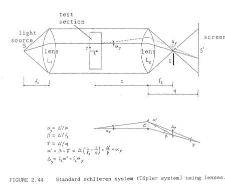
CHAPTER 4 - EXPERIMENTS BY THE SCHLIEREN METHOD IN RIB-ROUGHENED CHANNELS 4. 1 The apparatus
4. 1. 1 The test section 4.1. 2 The instrumentation 4.1. 3 The optical system 4.1. 4 The data processing 4.2 The geometry
4.3 Operating procedure 4.4 Results and discussion
4.4.1 The smooth channel
system
4.4.2 The rib-roughened channel Chapter 4 - Figures
CHAPTER 5 - CONCLUSIONS REFERENCES
APPENDIX Al - Liquid crystal thermography Al.1 Theory
Al.2 Measurement of thermal conductance of the test plate Al.3 Error analysis
Appendix Al - Figures APPENDIX AZ - Schlieren method
AZ.1 Theory
AZ.2 Thermal field reconstruction AZ.3 Data reduction
AZ.4 Error analysis Appendix AZ - Figures
page 73 74 II 75 II 79 II 82
page 106
II 106 II 106 II 107 II 108 II 111 II 111 II 112 II 112 II 113 118 II 125 page 160 page 163 page 173
NOMENCLATURE
Note: only the most relevant and recurrent symbols are included here
A heat transfer surface area, flow area
C Gladstone-Dale constant, thermal conductance
c speed of light
D diameter
d (equivalent) diameter
e rib height
f friction factor
Gr Grashof number (=Ra/Pr)
g acceleration of gravity
k thermal conductivity
H (channel) height
h heat transfer coefficient
L (channel) length
Nu Nusselt number
n index of refraction
P rib pitch, pressure
Pr Prandtl number
Q heat flux
q specific heat flux
R (ideal) gas constant
Ra Rayleigh number
Re Reynolds number
S wall spacing
St Stanton number (=Nu/RePr)
T temperature
t thickness
x,y,z geometric coordinates
w velocity, rib width
a angular deflection of light ray, rib angle-of-attack
~ coefficient of thermal expansion
~ difference, light ray deviation
µ dynamic viscosity
v kinematic viscosity
p density
-r time
0 dimensionless temperature
Subscripts
air air
av average
C cold
f fluid
fd fully developed
fp flat plate
h hot
max maximum
0 reference
r rough
s smooth
s,a surface, air side
s,w surface, water side
tp test plate
CHAPTER 1. INTRODUCTION
Heat transfer phenomena play an important role in numerous engineering
applications. The aim of the discipline of heat transfer is to describe
precisely the way in which the dissimilarity between temperatures of two
systems (which provokes a net heat transfer exchange) governs the magnitude
of the heat transfer rate Q. Generally speaking, experience shows that the
heat transfer rate function Q depends on the temperatures of the two
interacting systems, their thermophysical properties, size, geometric
shape, relative movement or flow, and time. Knowledge of the specific mode
of heat transfer (conduction, convection, and radiation) enables one to
consider simpler versions of the relationship between the cause
(dissimilarity between temperatures of the two systems) and the effect
(heat transfer rate). For instance, in convective heat transfer, which is
the major heat transfer process occurring between a solid wall and a fluid,
the conventional approach consists of relating the heat transfer rate Q to
the temperature difference between the two systems
TA-TB
through the heattransfer surface area A and the convective heat transfer coefficient h:
( 1. 1)
The evaluation of the heat transfer coefficient, which often
constitutes a very demanding question, is only the starting point in the
practice of heat transfer engineering. Two large classes of practical
applications need a further investigation of Eq. (1.1) to achieve the
relevant objectives.
The first class of problems includes applications in which a heat
transfer enhancement is required. Bearing Eq. (1.1) in mind, it means that
the major task is the augmentation of the heat transfer rate Q under the
same temperature difference
(TA-TB)
between the interacting systems. Inheat exchanger design, for example, if the temperatures of the two systems
are given, it is extremely desirable to have the maximum heat transfer rate
between the systems for the assigned heat transfer area (or exchanger
size).
The second class involves applications in which the main concern is
the overheating of the warm surface (at temperature
TA)
that produces theheat transfer rate Q. In a tightly packaged set of electronic circuits, Q
is generated by Joule heating, while
TB
is provided by an external fluid(TA) cannot rise too much above the ambient temperature, because high
temperatures threaten the error-free operation of the electrical circuitry
and tend to reduce the application life of the components themselves. In
this kind of application the main objective is the thermal control: in
fact, the high temperature TA must be kept below that critical domain where
the characteristics of the hot surface (e.g., the mechanical strength)
deteriorate.
For both the above-mentioned classes of problems, the key parameter to
investigate, to control and even to maximise is the heat transfer
coefficient h or the product between hand the heat transfer surface area A
(often called thermal conductance). The evaluation of the heat transfer
coefficient, through experiments or numerical means, is not a simple
matter. The more complicated the geometry or the flow, the more demanding
is the estimate of heat transfer coefficient. From the experimental point
of view, a large category of convective phenomena can be investigated by
using optical techniques. Optical measurement of a temperature field (to
which the heat transfer coefficient is directly related) has many
advantages over other techniques: for instance, it enables a simultaneous
analysis of a large fluid region to be performed and this in the absence of
instrument probes which could influence the phenomenon. In recent years,
the rapid evolution of computer facilities (image digitising and processing
systems, dedicated software) has made the use of some optical tecnhiques
(liquid crystal and schlieren methods) possible from a quantitative
standpoint and no longer for a qualitative observation only. This
possibility has opened new frontiers to scientists and engineers engaged in
heat transfer problems, giving them the chance to conduct experiments on
complex flow or geometry with the aid of simple and reliable measurement
means.
Among the optical methods suitable for evaluating thermal fields /
heat transfer coefficients, attention was focused, in this project, on two
specific techniques: the liquid-crystal method and the schlieren method.
While liquid crystal methods are generally used to measure the thermal
field on a solid surface, the schlieren technique enables the temperature
field in transparent fluids to be determined. Besides, the two methods are
based on different physical principles: liquid crystals exhibit a selective
index of reflection of white light depending on their temperature, while
non-isothermal flow. The two methods have in common their relative
simplicity, ease of operation and low cost when compared with other optical
techniques (such as interferometry). The last attributes make their
application very interesting in a wide field of engineering problems.
In the present study, the above-mentioned optical methods have been
applied to systems consisting of rib-roughened (and smooth) channels cooled
in forced/free convection. As will be documented later, this kind of
geometry is encountered in heat transfer enhancement as well as in thermal
control problems. In fact, keeping in mind the simplest heat transfer
geometries occurring in several high flux applications (i.e. of flat
surfaces or smooth inner/outer cylindrical surfaces), a very common
practice to increase heat transfer coefficients in forced convection
consists of artificially roughening the surface by fitting protruding
elements such as ribs. The use of repeated ribs causes a break-up of the
laminar sublayer and creates local wall turbulence due to flow separation
and reattachment between ribs, which greatly enhances the heat transfer. In
other applications, the roughness elements occur naturally (for instance in
electronic circuit boards and microelectronic chip modules). Here the
objective is to understand the thermal behaviour of rough surfaces (both in
forced and free convection) when a given amount of heat flux is dissipated
into the cooling fluid.
The specific applications for which heat transfer characteristics from
rib-roughened surfaces are of great importance will be presented in the
following sections 1.1 and 1.2. Finally, the role played by optical methods
in experimental investigations of convection over this complex geometry
will be discussed in the section 1.3 of this Chapter.
1.1 Heat transfer enhancement
Roughened heat transfer surfaces
problems which are extremely diverse.
can be encountered in engineering
One of the first applications of
rib-like geometries was in the field of gas-cooled reactors. Even though
gases are not good heat-transfer media, they have been extensively used as
coolants in reactors owing to their low neutron absorption and low chemical
activity. Usually the cooling gas flows in annular gaps between the
external surface of the fuel rod and the inner surface of the confining
(High Temperature Engineering Test Reactor) is shown (Takase et al. ,1994).
The element consists of a hexagonal graphite block with a number of holes
in which the fuel rods are inserted. In this application the coolant is
helium (heated from 395°C up to 950°C) at the pressure of 4 MPa. Ribs or
artificial roughness elements can be used in order to enhance forced
convection heat transfer from the external surfaces of the rods. Adding the
ribs to the external rod surface increases the turbulence in the annular
flow. As a consequence, both heat transfer and friction losses are
increased. While the latter effect implies a higher amount of power
required to pump the fluid (which generally does not constitute a problem),
the former effect enables the core power density to be increased, thus
reducing the electrical power generating costs.
In the last decade, the demand for increasing thermal efficiency in
turbomachinery and other rotary systems has promoted a great effort in the
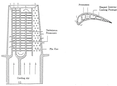
development of efficient techniques for cooling turbine blades. Internal
cooling technologies, involving passages between roughened surfaces, have
been applied to advanced gas turbine blades. As depicted in the cutaway of
Fig.1.2, a succession of rib turbulators are installed on the internally
cooled turbine airfoil. When the cooling passages are roughened with ribs,
heat transfer to the cooling air within the blade is significantly
enhanced. The geometries involved in this application differ from the
previous one (as do the boundary conditions at the walls) but, from the
conceptual point of view, the heat transfer augmentation is provoked by the
same physical phenomenon, that is the vortex generation and high turbulence
levels which improve the heat exchange from the walls.
Artificially roughening internal/external surfaces of pipes and
channels is also a common practice in heat exchanger design. Compact heat
exchangers, for instance, require high heat transfer surface areas (and
high heat transfer coefficients) concentrated in a small heat exchanger
volume. Hence, any solution (adding ribs, for instance) which increases
heat transfer is welcome here. Figures 1. 3 (a) and (b) show externally
finned pipes and internally rib-roughened passages, respectively. The use
of these surfaces ranges from the automotive industry to control systems in
aircraft vehicles.
So far forced convection heat-transfer applications have been
presented. Natural convection flows are of interest in a number of
compared with those in forced convection, natural convection heat transfer
is an attractive mechanism (for low-density energy production systems)
owing to its reliability, simplicity and cost effectiveness. In some
applications (cooling of electronic devices for telecommunications) it is
even the only feasible way of removing the heat produced as the use of fans
can disturb the correct working of the equipment.
A different approach to the study of heat transfer enhancement
problems in free convection is generally required. In fact, in a forced
convection problem, the heat transfer augmentation provided by the enhanced
system (with respect to a reference unaugmented system) under given
constraints (at fixed mass flow rate, for instance) occurs at the price of
higher pressure drop and pumping power. Since the mass flow rate is
controlled independently of the thermal problem, the penalty of higher
costs to pump the fluid can be accepted if the heat flux exchange is the
major task. In a natural convection system no energy costs are needed to
pump a given mass flow rate. In fact, if a system operates in a natural
convection situation, the flow rate is not externally controlled but
derived from a balance between the buoyancy and the friction forces. Thus,
higher friction, occurring for instance when a flat surface is artificially
roughened, leads to a lower flow rate which tends to reduce heat transfer.
Conversely, the augmented heat transfer surface area as well as the
modified local heat transfer characteristics (for example vortex generation
or fluid recirculation) generally cause an increase in heat transfer which
may or may not counterbalance the negative effect related to the reduction
in mass flow rate. Therefore, it is not possible to establish " a priori"
if a rib-roughened surface, which represents a forced convection enhanced
system, could be regarded as an enhanced system in natural convection.
Three examples of possible enhanced surfaces in free convection are
shown in Fig.1.4 (Fujii et al.,1973). The external surface of a cylinder,
cooled by a liquid in natural convection, is roughened using repeated ribs
(Fig.1.4 a), dispersed-protrusion elements (Fig.1.4 b), and dense-pyramid
elements (Fig.1.4 c). Increases in the average heat transfer coefficients
in the range 0-10% were observed relative to data for a smooth cylinder. In
spite of this result (and others obtained for similar configurations), the
literature seems somewhat contradictory with some researchers finding
increases of 100% and others finding no increases and even decreases
transfer, then it is important to understand how various surface
modifications (for instance a vertical rib-roughened surface or channel)
produce this enhancement.
1.2 Thermal control
Understanding the thermal performance of systems on which the
roughness is present naturally is of great importance when the main concern
is the thermal control of the surface. Electronic equipment packages
represent an industrial situation in which convective heat transfer in
roughened channels is encountered. In current designs of low-power-rated
electronic components on printed circuit boards, specific consideration is
given to heat transfer analysis to achieve high heat dissipation rates and
to limit peak temperature levels. Currently, low Reynolds number forced
convection and natural convection heat transfer are useful to guarantee the
appropriate working temperature of components. In most of the recent
literature, the circuit board is simulated by an array of heated square
blocks deployed along a wall of a parallel-plate channel, as depicted in
Fig. 1.5 (Faghri and Asako, 1994). The problem has been investigated
numerically (even by three-dimensional analysis but in the laminar regime)
and experimentally (using a two-dimensional test section). Natural
convection cooling of electronic equipment continues to be an important
thermal control mechanism in applications such as telecommunications
electronics, in which long term reliability is an overriding design
criterion, and consumer electronics in which acoustic noise is undesirable.
In typical "passive" cooling applications (i.e. free convection cooled),
densely packed boards are vertically oriented in order to promote the most
effective buoyancy flow condition (Fig. 1.6, Choi and Ortega, 1993).
Other applications of studies on free convection from arrays of heated
roughness elements include the design of solar collectors, fluid-filled
thermal storage tanks, operation and safety of nuclear reactors, and fire
prevention and safety.
1.3 Why use optical methods in experiments on rib-roughened channels?
The applications mentioned in the previous paragraphs demonstrate the
in rib-roughened channels. Owing to the complexity of the geometry, the
ability to predict analytically and numerically the effect of the ribs on
the flow field and heat transfer is limited. Therefore, experimental
investigation is the most reliable and effective approach to verify the
influence of the relevant geometrical parameters on heat transfer and
friction characteristics. In this connection optical methods represent an
extremely versatile tool for making quantitative measurements of thermal
phenomena. In complex flow situations, such as those encountered in
convection from ribbed surfaces, the use of traditional sensors
(thermocouples, for instance) does not permit whole-field information to be
obtained on the observed phenomenon (unless the displacement of a very
large number of miniaturised sensors in the test section is provided) and
may alter flow and thermal characteristics owing to the physical presence
of the probes. These disadvantages are efficiently overcome by optical
methods, which allow a non-intrusive analysis over the whole optical field.
A large variety of optical methods is currently employed in experimental
investigations of complex flows. Most of them are based on physical
principles known since the last century. Their use has mainly been
qualitative for several years. The recent development and wide-spread
availability of inexpensive video digitisers combined with the increased
power of computers has made routine digital image analysis feasible. It
means that, if the relationship between the optical parameters recorded and
the temperature (or the temperature gradient) is well established, the
digitised optical field can be, in real time, processed and converted in
the thermal field, or, alternatively, the thermal parameters of interest,
FIGURE 1. 1.
Test Reactor.
FIGURE 1. 2.
Pickup hole
Graphite block
Dowel
Fuel
Dowel
R
i n c ,o
c:;, ~ ,"":=~~~~O~C>~~~~/
!I.
LJU!!i
tlij'i ~ ~w~ ,:I-1, y lit < ~ <--. '
i
11
1ti
i..1nw.,i~~
:
r o d ,
"NI
i
I
ii
iii! · :11I
f \i'
:
I
\I \!!i
:,'.-~I
I, iI
:i iii! I ii'i-1. i 1
!
1
ii
ii
ii
1 . . ::::E-Ii11 'l '/tt 1
I
ij
j1
!! ,
oi
I
I
;i 'Iii!.
ii, '1 ~ . I , CD t.0[ II
~
:
1 :11
1i
I
1 1 II
I:.r;
1' I I ' I I!I
,,11 I ! , I :' ' 'i'I , 11 ' I
I l 1jl' ' \ 'I l i
·1· ti ,Ir.
i
I
! ! 1 !i
~,_Jly
[i
i.~
1v
/i
r socket ' - - ; ~A fuel element with 33 standard fuel rods in High Temperature
P!_a flru
(a)
I
J:
---'-==0>---
-
}-71
\
y· ~
FIGURE 1.3. (a) Externally finned tubes and (b) internally roughened
---1--·
J . . . - - - - 7 3 ¢ - - ~ ~
I
(a)
s = 3·2. 6 <1, 12·Bmm
g
C
_...,_
____
, - - - - ~ ~ I_ _ _ _ 73<±,____ 0·5 ..!..---+-I_.----.-,;,.,
i '
k---66¢--...i
t
. I
-r ---
! - -
:-==r
- - · sL · - -
J
(b)
.rr
0
0 0 0
- - - - ? ~ ¢ - - - - ~
.c
u
":: 0
a. 0 0
T~~T~~Jl
I
so1Detail of port B
(c)
FIGURE 1.4. External surface of a vertical cylinder roughened by (a)
_J ! _ i L__J L__J L____l L
JDDBEJ[
I
s . _<>]DODD[
L
7D· ;-
zD
[J
A
J
:.
A... -.. ~
=JD.DOD[
FIGURE 1. 5. Schematic diagram of array of rectangular modules along a
flat plate simulating a circuit board.
---
---r
~ ~ ~
~ ~ ~ ~
r
~ ~ ~ ~
~ ~ ~ ~
r r r r r
r r
n
r r r r r
r
~
r
r r
--- .
-l -l -l t I
I
t
l l t
CHAPTER 2.
LITERATURE SURVEY
A considerable number of flow and heat transfer studies in
rib-roughened channels is documented in the technical and scientific
literature. A general review of the wide bibliography dealing with heat
transfer from roughened surfaces could be organised according to different
criteria: the chronological order, the approach followed in the study
(theoretical, numerical, or experimental), the application, and so on. In
addition, as stated in the previous Chapter, artificially roughened
surfaces can be encountered in applications involving flows in either
forced or natural convection. Therefore, a subdivision of published papers
based on the nature of the convective flow was deemed to be the most
appropriate choice. Even though similitudes and connections between forced
and natural flows on ribbed surfaces are present, the nature of flow
(forced or natural) affects the extent of heat exchange, the distribution
of heat transfer coefficients and the features of the experimental
apparatus. For example, the experimental study of forced convection
requires wind tunnels, heaters able to supply large quantities of power to
the fluid, flow rate and pressure instrumentation devices and other
equipment. The experimental study of natural convection generally requires
less demanding equipment but it has to be performed in a laboratory with
high thermal stability and isolated from external disturbances (without
external walls, vents and thermal sources).
The consideration that this project consists of two separate
experimental parts which differ owing to the nature of the air flow (and to
the different optical method employed) is a further reason to support the
classification of the references in the two following groups:
2.1 Forced convection from rib-roughened surfaces;
2.2 Natural convection from rib-roughened surfaces.
A third section 2. 3 will contain a brief review of optical techniques
suitable for convective heat transfer investigations, with specific
interest for methods employed and developed here (liquid crystal and
schlieren methods).
2.1 Forced convection from rib-roughened surfaces
a selection of them will be discussed and quoted in the list of references.
The majority of studies involve experimental investigations of
two-dimensional geometries. Also, numerical analyses have been developed in
the last decade, both for the laminar and turbulent flow regimes.
2.1.1 Historical background and state-of-the-art
The effects of surface roughness on flow and heat transfer
characteristics have been investigated since the first decades of this
century. While initial studies were inspired by the need to clarify
phenomenological aspects of the problem, specific applications (heat
transfer enhancement in gas-cooled nuclear reactors) necessitated the
performance of experiments in annular passages. The majority of experiments
conducted in the 50' s and 60' s were developed in annuli with heated
roughened inner and unheated smooth outer surfaces, thus simulating as
closely as possible conditions occurring in the cooling of fuel element
rods. Alternatively, rectangular channels with the ribbed plate heated and
the other (smooth) plates unheated were considered.
The main challenge faced in those years concerned the most convenient
format of presentation of the large quantity of experimental data obtained.
Since the characteristics of the roughened surface were of primary
interest, different methods were proposed to separate the properties of the
two surfaces forming the annulus (or the channel). The first method
developed was called the "Hall transformation" (Hall, 1958). This method
assumes that the surface of zero shear stress is a boundary within which
the structure of the turbulence is unaffected by changes in the structure
occurring beyond the surface. For instance, in a channel formed by two
infinite flat plates, one rough and one smooth (Fig. 2. 1 (a) ) , the flow
between the region of the rough surface and the plane of zero shear stress
would be unaffected if the smooth plate were removed and replaced by an
identical rough plate but at the same distance as the first rough plate is
from the plane of zero shear stress (Fig.2.1 (b) ). Further assumptions are
that the surface of zero shear stress coincides with the surface of maximum
velocity (y) and that the use of the equivalent diameter defined by the
m
flow area between the roughened surface and the surface of maximum velocity
accounts for a change in passage shape so that results apply to a roughened
circular pipe, for example. Measurements of velocity and temperature
profiles in the passage allow mass flow rate and equivalent diameter to be
Reynolds number can be calculated for the roughness region only. Similarly,
assuming that the line of zero shear stress and the adiabatic line are
coincident, it is possible to calculate transformed heat transfer
coefficients (generally recast in dimensionless form, Nusselt or Stanton
numbers) for the roughened region from temperature distribution data.
Unfortunately the measurement of velocity and temperature profiles in
the passage, required to localise the maximum velocity line, is demanding
and time-consuming in most experimental situations. Therefore Wilkie
( 1966) proposed a simplified method which does not require velocity (and
temperature) profile measurements. From detailed local measurements in
different annuli he evaluated the average velocities w and w in the two
r s
regions (rough and smooth, respectively) of the annulus (separated by the
maximum velocity criterion) and the (transformed) friction factor f of the
r
inner rough surface. He found that the ratio w /w depends on the ratio
r s
f If (f being the friction factor of
r r0 r0
transformed Reynolds number, assumed to be
is lower than two (Fig. 2. 2). When f If
r r0
a smooth pipe at the same
-0 2
0. 046 Re · ) only when f /f
r r r0
is larger than two, the two
average velocities w and w are equal within 2 percent. Therefore, the
r s
assumption w =w =w (w being obtained from the measured mass flow rate) can
s r
be made. The (transformed) equivalent diameters of rough and smooth regions
d and d and the friction factor f of the rough surface can be derived
s r r
from the solution of the following set of equations:
w =w =w
s r
d =4A Ir
s s s
d =4A Ir
r r r
A= A +A
s r
~P/L=f (4/d )(1/2pw2)
r r r
~PIL=f (41d )(1/Zpw2)
s0 s s
f = 0. 046 Re -o.2
s0 s
(2.la)
(2.lb)
(2.lc)
(2.ld)
(2.le)
(2. lf)
(2.lg)
where A is the annulus flow area, A
r is the flow area between the rough
surface and the plane of maximum velocity, and A is the flow area between
s
the plane of maximum velocity and the smooth surface. r and r represent
r s
the (known) perimeters of the rough and smooth surfaces, respectively,
while ~P/L is the measured pressure drop along the annulus length L. In
Eq . ( 2 . 1 g) , Re
s is based on w and on the unknown equivalent diameter d . s s
Results from rectangular and annular channels showed that the transformed
progressively rougher surface, this being in contrast to the concept of the
separation line between smooth and rough zones. Wilkie took into account
the departure of transformed smooth friction factor f from f (=0. 046
s s0
Re-2) by introducing in his simplified transformation method a further
s
empirical relationship between (f /f ) and (f /f ).
s s0 r rO
The partial failure of the Hall transformation method lies in the
fact that in annuli with strongly asymmetric velocity profiles there is no
coincidence between the lines of zero shear stress and of maximum velocity,
the position of no shear being shifted towards the outer smooth surface
(Kjellstrom and Hedberg, 1966). Therefore a different method was proposed
by Maubach (1969, 1972) known as the "Maubach transformation". This method
is based on the existence of dimensionless velocity profiles obeying "the
law of the wall" :
+ +
w
=
A ln y + Bs s
w+=A ln(y/e) + R
r r
(2.2a)
(2.2b)
where w+ stands for the local streamwise velocity normalised by the
friction velocity (T /p)1/2. The slopes A and A are generally taken to be
w r s
the same and equal to 2. 5. The parameters B and R can be determined by
experimental results. In order to separate the two zones in asymmetrical
flows Maubach assumed that the zero shear stress line is given by the
intersection of the two velocity profiles originating at the respective
walls. A good agreement with the experimentally determined line was found.
Once the separation line has been obtained, integration of equations for w+
s
and w+ over the respective flow areas yields the relevant friction factors
r
and Reynolds numbers. Further modifications to this method were proposed by
Dalle Donne and Meerwald (1970), Warburton and Pirie (1973), Dalle Donne
(1976) and Dalle Donne and Meyer (1977).
In spite of the different ways of recasting data, the proposed
transformation methods are valid from an engineering standpoint and
distinctions between data transformed by the Hall or Maubach methods can
be generally neglected.
Once the different methods of interpretation of experimental results
are clarified, it should be pointed out that further discrepancies appeared
in the results of various investigators even when analysed by the same
transformation method. This is due to the frequently poor definition of the
unfeasible), to the different geometric conditions (for example annuli with different radius ratios, rectangular channels, parallel plates), and to the different quality of the experimental approaches. The problem is complicated by the large number of parameters involved. Therefore, the validity of results proposed by each author is limited to the parameter ranges indicated and the poor agreement between data obtained in similar conditions makes it difficult to generalise the effect that a specific parameter is expected to have on friction and heat transfer characteristics.
The first attempt to correlate heat transfer results obtained in annuli (with heated roughened inner and unheated smooth outer surfaces) was conducted by Gomelauri (1964). The proposed relationship is based on data obtained by Nunner (1956), Fedynsky (1959), Brauer (1961) and Gomelauri (1964) and expresses the Nusselt number as a function of the untransformed Reynolds number (based on the equivalent diameter of the annulus):
Nu = 0.0218 Re0"8Pr0"4(Pr /Pr )exp(f (P/e))
f f f f w n (2.3)
where the subscripts f and w refer to properties evaluated at the film temperature (average between wall and bulk temperatures) and at the wall temperature, respectively. Further:
f (Pie) = 0.85 (Pie) /(Pie) when Pie ::!:: (Pie)
n opt opt
f (Pie) = 0.85 (P/e)/(P/e) when Pie ~ (Pie)
n opt opt
(Pie) =13· 3 3 l<Pr<80.
opt ' 6x10 <Re<90x10 ;
Since the relationship (2.3) correlates data obtained for square, triangular and rounded roughness elements, it is expected to be somewhat roughly approximated, even if adequate for engineering calculations.
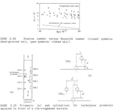
One of the most important and exhaustive studies on the effects of the geometrical parameters on friction and heat transfer characteristics was performed by Wilkie (1966, a). He collected heat transfer and pressure drop data from annuli with heated roughened inner and unheated smooth outer surfaces (Fig.2.3) interpreted by means of the Hall transformation. Effects of geometric parameters P/e and e/d (the latter not evidenced by Gomelauri) as well as of the transformed Reynolds number Re were discerned. According to the Hall transformation, the equivalent diameter d is defined as 4A/r where A is the flow area between the rough surface and the maximum velocity surface (at the distance y ) and r is the perimeter of the wall surface
m
height e varied from 0. 1 to 1. 6 % of the equivalent diameter d of the
annular passage and the rib pitch to height ratio Pie from 2. 5 to 50.
Further experiments (without heating) were conducted for rib-width to
rib-height ratio wle from 0.5 to 2.5. The following main conclusions were
reached:
( i) friction factor is independent of Re at high Re and eld as shown in
Fig. 2. 4;
(ii) the variation of St number (St=NulRePr) with Re depends on eld; as
emerges from inspection of Fig.2.5, small eld exhibit less variation than
large eld, the latter showing the same variation as smooth surfaces;
(iii) the friction coefficients and the St numbers for the rough surfaces,
normalised by the relevant values for a smooth inner surface and plotted
against Pie (Figs 2.6 and 2.7, respectively) show a maximum. The Pie value
giving maximum friction and maximum Stanton number varies with eld (the
lower the eld, the higher the Pie) and it is almost independent of Re (in
5
the range Re=1-3x10 ). The two maxima are obtained for Ple=6 at large eld
and for Ple=6-8 when eld=0.01-0.016. Reducing eld implies a larger Pie
value (=(Pie) ) to achieve the best relative heat transfer performance
opt
(Fig.2.8); this information is crucial for the correct design of annular
passages with internal rough surfaces. Since Gomelauri (1964) did not
consider eld as an independent variable (its effect is diluted in his
definition of Re), direct comparison between (Pie) obtained by Wilkie
opt
(Fig.2.8) and Gomelauri (=13) is not feasible.
Finally, Wilkie investigated the effect of wle for a limited number of
experiments (at constant Pie and eld). Strong reductions in friction can be
achieved by increasing the rib width to height ratio (Fig. 2.9); no heat
transfer data were obtained in these conditions.
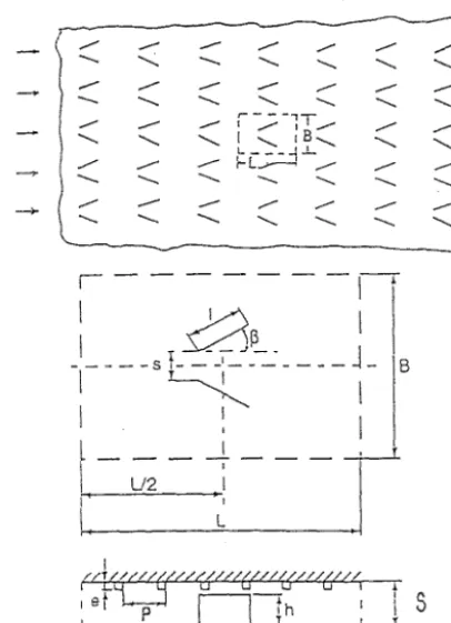
The effect of the roughness shape was investigated by Williams and
Watts (1970). Ribs having square, chamfered and wedge profiles were tested
in a rectangular channel. In order to gain a better understanding of the
reasons for the differences found among the three types of rough surface,
flow visualisations were carried out, using small polystyrene particles
dispersed in the water flow. The picture which emerged from this
investigation is essentially a sequence of vortices starting, growing, and
5
then moving downstream as in Fig.2.10 for (untransformed) Re=1.7x10,
Ple=7. Visualisations showed that reducing the pitch to height ratio Pie
between the ribs occupying approximately two thirds of the cavity. This
explains the noticeable reductions in heat transfer performance found by
Wilkie (Fig. 2. 7). In addition, local heat transfer coefficients at P/e=7
and 3 were evaluated, by a mass transfer analogy technique, for square,
chamfered, and wedge ribs (Fig.2.11 (a) and (b) ).
Interest in local flow and heat transfer characteristics was
progressively becoming the main concern of investigations in view of the
availability of considerable global flow and heat transfer information.
Local velocity and pressure profiles obtained by Aytekin and Berger (1979)
and Meyer (1980) led to quantitative assessments of the mainstream
reattachment length (Fig. 2. 12) and to a refined dimensionless velocity
distribution in the rough zone without the assumption of a constant profile
slope (Fig.2.13) A further contribution to the local heat transfer
analysis in systems simulating fuel element cooling in Advanced Gas-cooled
Reactor (AGR) was given by Lockett and Collins (1990). Their experimental
local heat transfer coefficients were obtained by means of an
interferometric analysis applied to square and rounded rib-roughness
elements. For square ribs (Fig. 2. 14), local coefficients on the forward
facing rib wall were found to increase from the base to the tip of the rib.
On the rib top, Nu generally decreases far from the leading edge, with
strong reductions on the rear facing rib wall. In the inter-rib region, the
Nu number has an initial peak downstream of the reattachment point. The
growth of the boundary layer after the reattachment is responsible for the
subsequent decrease. A second peak in the Nu distribution was observed very
close to the trailing rib corresponding to the reattachment point of the
secondary recirculation in the corner between the inter-rib space and the
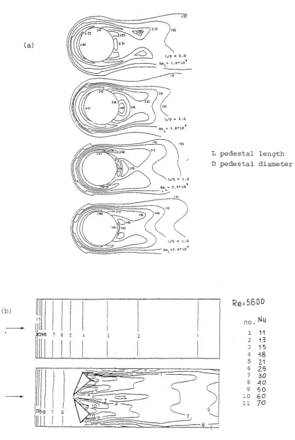
forward facing rib wall. Recently, Aliaga et al. (1994) performed accurate
local heat transfer measurements and flow visualisations for the same
geometry (a heated plate with square ribs opposed to an adiabatic plate)
including the fully developed region as well as the entrance region, as
shown in Figs. 2.15. Even though results refer to a small range of Reynolds
number (1.0-1.5 106), they are useful in clarifying the complex
interactions between the flow field features and the local heat transfer
performance. It was found that for the smaller pitch-to-height ratio a
single recirculation bubble is formed in the cavity between consecutive
ribs and heat transfer is impaired. For the larger Pie value, however, the
transfer decrease between the reattachment and the (second) separation
points (Fig. 2.16). Finally, different heat transfer coefficient profiles
were identified around the first three ribs owing to possible flow
distributions (Fig.2.17).
Since the 1970' s, the demand for increasing thermal efficiency in
numerous engineering sectors (heat exchanger design and turbomachinery, for
example) has promoted great efforts in the development of heat transfer
enhancement techniques. As a consequence, the traditional annular geometry
(with one heated rough surface and the opposite unheated smooth surface),
simulating a typical nuclear reactor situation, was progressively abandoned
in favour of more complex geometries. These involved two or three
dimensional channels roughened on one or more sides with ribs of different
shape and inclination.
Webb et al. (1971) were among the first to develop a generalised
understanding of the friction and Stanton number characteristics of
"repeated-rib" roughness in turbulent pipe flow. The study provided
correlations for f and St for e/d (d being the "transformed" equivalent
diameter) between 0.01-0.04 and Pie between 10 and 40, in addition to
drawings of flow patterns as a function of Pie (Fig.2.18).
Han et al. (1978) considered a geometry consisting of two parallel
plates roughened by symmetric and staggered ribs. Results were presented
without a transformation for data reduction. In the ranges of parameters
investigated, the Stanton number is maximised for Pie= 10, which is not
too far from values suggested by Wilkie for an annular passage
asymmetrically heated. Some years later, Han (1984) extended the analysis
to square ducts with two opposite rib-roughened walls (Fig.2.19),
addressing his study specifically to turbine blade internal cooling design.
The combined effect of the rib-angle-of-attack and the channel aspect
ratio on the distributions of the local heat transfer coefficient for
developing flow in rectangular channels with opposite rib-roughened walls
was determined by Han and Park (1988). Owing to the entrance effect, for a
square channel roughened by ribs with angle-of-attack normal to the main
flow, the (periodic) Nusselt number decreases in the streamwise direction
and then reaches a constant periodic distribution after three times the
hydraulic diameter of the channel (Fig.2.20). Some modifications are
induced by a different angle-of-attack in square and rectangular channels.
channel at the same Re) were obtained for the square channel with ribs at
an angle-of-attack a=60°; this is apparent from inspection of Fig. 2.21.
Several experimental contributions are reported in the literature of
the 1980' s and 1990' s. The majority of papers are aimed at the specific
application of turbine blade cooling and therefore the ribbed passage under
study is subject to further modifications in order to represent as closely
as possible the application. For instance, a rotating serpentine passage
with rib-roughened surfaces was studied by Fann et al. 1994.
So far, most of the relevant experimental work dealing with flow and
heat transfer characteristics for rib-roughened surfaces has been
mentioned. It is apparent that the geometries investigated were strictly
related to the specific applications: asymmetrically heated annular
passages for nuclear reactor cooling problems (from the 1950' s to the
present day), square and rectangular channels with different conditions of
heating and roughness at the walls for turbomachinery, heat exchangers and
electronic equipment cooling problems (in the last two decades). Owing to
the complexity of flow features in channels with rough walls, only in a few
studies has the problem been tackled analytically or numerically. The first
attempt to determine analytically the roughness functions for flow over
rectangular ribs was made by Lewis (1975). The flow was approximated by a
series of attached and separated flow regions, and some empirical
information from experiments over cavities and steps was required. One of
the first numerical analyses for forced convection heat transfer from
rib-roughened surfaces was conducted by Rowley and Patankar (1984). The
geometry investigated was a tube with internal circumferential fins cooled
by a laminar flow of fluid at different Prandtl numbers (Fig.2.22). It was
found that the ribs do not always increase heat transfer in the laminar
regime. Despite the increased area provided by the ribs, the distortion of
the flow that the ribs cause (with weak recirculating motion between
adjacent ribs, Fig.2.23) can substantially diminish the heat transfer from
the duct wall and thus lower the overall heat transfer. In particular, for
a Prandtl number typical for air (Pr=0.7), a reduction in heat transfer was
always obtained (Fig.2.24).
The numerical study of turbulent convective flow in rib-roughened
channels implies a higher degree of complexity of the problem, owing to the
four-dimensional (three spatial, one time, coordinates) character of
flow regime were based on the k-e turbulence model (Wilkes, 1980, Fodemski
and Collins, 1988, Lee et al. ,1988, Takase et al. ,1994 among others). More
recently LES (Large-Eddy Simulation) results have been obtained for
turbulent flow and heat transfer in a plane channel with transverse square
ribs on one side (Ciofalo and Collins, 1992). Local heat transfer results,
compared with k-e predictions and experimental data, presented many
features in agreement with experimental data not evidenced by k-e
simulations. For instance, the second Nu maximum in the reattachment region
was predicted, as shown in Fig.2.25.
2.1.2 Experimental t~chniques
This project is mainly based on an experimental programme dealing with
heat transfer from rib-roughened channels. Therefore, in the literature
review, particular attention is given to the experimental techniques
developed to obtain heat transfer data. As discussed in the previous
paragraph, at first the main concern was overall heat transfer performance
in annular passages. Typically, heat transfer experiments were conducted
using a cylindrical electric heater located inside the inner, rib-roughened
tube, while the outer smooth tube was thermally insulated. The test section
included a very large number of repeated ribs in order to gain fully
developed flow and heat transfer conditions. Because of the thermal
conductivity of the inner tube material, the temperature tended, in these
systems, to attain a nearly uniform profile along the surface (with small
increases from the entrance to the exit) in spite of the uniform heat flux
dissipated by the heater. Therefore the thermal boundary condition at the
heated wall was often somewhere between uniform heat flux and uniform
temperature conditions. Thermocouples were generally deployed in small
holes drilled in the inner (rough) tube at several locations (to record the
mean heated wall temperature T ) and in the inlet/outlet sections (to
w
record a mean coolant temperature T ). Since the dissipated heat flux (by
f
Joule effect) could be easily measured, the mean heat transfer coefficient
hat the inner rough surface is derived from the simple relationship
h = Q / [A (T -T ) ]
w f (2.4)
where A is the heat transfer surface area and Q is the electric heat flux
corrected to take into account radiation heat exchanges and conduction heat
losses.
transfer observations. In fact, if the local heat transfer coefficient is
required, the above relationship needs to be applied on a local basis.
Since the wall temperature or the specific heat flux to the fluid may
change from point to point (as well as the local bulk temperature of the
fluid), care must be taken to ensure well-defined thermal boundary
conditions and to make measurements of the surface temperature in detail
(that is in a large number of spots). This is shown, for instance, in
Fig.2.26 (Hong and Hsieh, 1993). The manufacture of a similar test section
is time-consuming and expensive. In addition, many measurements need to be
performed and processed in order to reconstruct local heat transfer
coefficients limited to a discrete number of locations, namely those
monitored by thermocouples. To overcome these fundamental difficulties,
methods based on the heat/mass transfer analogy and optical techniques were
successfully applied to the study of rib-roughness geometries. A
description of methods employed as alternatives to thermocouples
measurements is given in detail. Comparisons of results obtained by some of
the above-mentioned methods will be presented in section 3.4.3.
(a) Thin film naphthalene.
The similarity between the mechanism of heat and mass transfer can be
used to evaluate heat transfer coefficients. If the surface is covered by a
uniform thickness of a volatile substance (for instance naphthalene), the
local thickness variation after a predetermined period of flow exposure
indicates the mass transfer (equivalent to the heat transfer) from the wall
to the fluid. No heating of the test section is required. Kattchee and
Mackiewicz (1963) performed experiments for rib-roughened surfaces with Pie
=7 and 8.5. Sparrow and Tao (1983) used this technique to study local heat
transfer from a wall with rod-type disturbance elements oriented transverse
to the flow direction. The correct application of this technique requires
extra care in the naphthalene deposit, which must have a uniform thickness;
this operation may be time-consuming and expensive, particularly for
complex surface geometries.
(b) Evaporation from water absorbent paper.
The heat/mass transfer analogy can also be applied by covering the
surface with a layer of absorbent paper previously impregnated with a
solution of cobaltous chloride. At the start of each test, the surface is
a bright pink colour. The time interval between the start of the flow and
the colour change (from pink to blue) is proportional to the local heat
transfer coefficient. This technique was developed and applied to
rib-roughened surfaces (P/e=7) by Williams and Watts (1970).
(c) Electrochemical analogue technique.
The transfer rate of certain ions in aqueous solutions to an electrode
is proportional to the local heat transfer rate. An aqueous solution of
potassium ferri- and ferrocyanide with sodium hydroxide as the inert
electrolyte was used by Berger and Hau (1979). A strip of nickel was used
as the anode and a ribbed surface of nickel as cathode. The measurement of
the electric current at certain stations around the surface enables the
heat transfer coefficient distribution to be determined.
(d) Copper foil technique.
This method involves the use of a series of copper strips placed on a
ribbed surface. If the dependence of electrical resistance on the
temperature of the strips is known, then ranges of known electric power may
be dissipated into the strips, giving uniform heat flux over the ribbed
surface. Then the readings of the voltage drop and current across each
strip allow the heat transfer coefficients (averaged on each strip) to be
determined. If numerous thin strips are fitted onto the ribbed surface, the
local heat transfer coefficient distribution can be extracted (Watts and
Williams, 1981).
(e) Holographic interferometry.
The above mentioned techniques present several inconveniences: poor
resolution, uneasy machining of the test section, availability of relative
and not absolute results (a,b,c methods), no information on the flow field.
Holographic interferometry (as well as classical interferometry from which
the former represents an evolution) provides a method which is optical,
non-invasive and whole-field in character, and can investigate thermal
effects. This technique was applied to the study of forced convection from
rib-roughened surfaces by Walklate (1983), Lockett and Collins (1990), and
Liou and Hwang (1993).
(f) Thermographic methods.
Owing to the recent developments in image processing as well as
recognition as appropriate research tools in the evaluation of heat
transfer performance of complex geometries. Infrared thermography was used
by Aliaga et al. ( 1994) to determine heat transfer coefficients along a
surface with a series of repeated square transverse ribs. In particular,
infrared thermography gave the local wall temperature for a known wall
emissivity, while local heat flux was measured as a difference between the
electrical power and conductive/radiant calculated losses. As an
alternative to infrared thermography, which involves the use of expensive
devices and extra care in the operating procedure, thermochromic liquid
crystals can be used. Liquid crystal thermography enables the wall
temperature pattern to be obtained and then the heat transfer coefficient
distribution to be reconstructed. Liquid crystals, deposited on thin sheets
directly attached to the ribbed surface, need only to be illuminated by
non-coherent light under suitable conditions. The reflected image, which
contains a colour pattern related to the wall temperature field, is
recorded by a camera, and then digitised and processed even in real time.
No systematic experiments using liquid crystals on rib-roughened surfaces
are reported in the literature. The present report will show the ability of
liquid crystal thermography to obtain detailed distributions of heat
transfer coefficient on complex surfaces involving the placing of ribs in
both transverse and normal directions to the flow.
2.1.3 Future developments and areas of research
For roughened surfaces with transverse square ribs the effects of the
rib height, the rib pitch and the channel equivalent diameter on the fully
developed average heat transfer and friction factor are well established
over a wide range of Reynolds number. Modifications to the basic rough
geometry have been introduced, by considering an angle of attack different
from 90° (inclined ribs instead of transverse) and different shapes of ribs
(rectangular, chamfered, wedged and rounded); heat transfer performance
improved in some cases.
The majority of experiments have shown that the poorest heat transfer
regions occurred downstream of the ribs, where a recirculation zone is
formed. Conversely, heat transfer coefficients are high after the
reattachment length and along the forward facing rib wall (for the fluid
impingement) and the rib top. Therefore, one possibility of improving heat
transfer conditions is to create more turbulence particularly in the less