Ahlin, G.A. and Brown, R.E. (2009) Wake structure and kinematics in the vortex ring state. Journal of the
American Helicopter Society, 54 (3). 032003 1-18. ISSN 0002-8711
http://strathprints.strath.ac.uk/
27488
/
Strathprints is designed to allow users to access the research output of the University of
Strathclyde. Copyright © and Moral Rights for the papers on this site are retained by the
individual authors and/or other copyright owners. You may not engage in further
distribution of the material for any profitmaking activities or any commercial gain. You
may freely distribute both the url (
http://strathprints.strath.ac.uk
) and the content of this
paper for research or study, educational, or not-for-profit purposes without prior
permission or charge. You may freely distribute the url (
http://strathprints.strath.ac.uk
)
of the Strathprints website.
Wake Structure and Kinematics in the Vortex Ring State
Gary A. Ahlin1 Richard E. Brown∗
Postgraduate Research Student Mechan Chair of Engineering Imperial College University of Glasgow
London, UK Glasgow, UK
High-resolution computational simulations of the vortical wake of a rotor operating both near to and within the vortex ring state have been conducted using Brown’s vorticity transport model. The nonlinear vortex kinematics of the wake is exposed using three-dimensional visualizations of the simulated flow field. To reveal the vortex dynamics that underpin the highly unsteady flow within the vortex ring state, a rotor with just one blade was modeled. This blade was decoupled aerodynamically from the surrounding velocity field so that it acted merely as a source of trailed vorticity. The investigation identified a significant change in the dominant dynamics of the wake as it swapped from the tubular form that is characteristic of hover or very low speed descent into the toroidal geometry of the vortex ring state. Initial vortex “pairing” leads to rotation of vortex filaments away from their original attitude. This phenomenon plays an important role in regulating the downwash that the rotor can produce and thus in precipitating the onset of the vortex ring state. The considerable and persistent coherence of the vortical structure of the wake when in the vortex ring state is revealed, despite these disturbances, as are the mechanisms that lead to both small-scale and large-scale wake breakdown events. Simulations show the balance between the vortex pairing and short-wave instability modes to be different in the vortex ring state at high descent speed, where the wake lies above the rotor, compared to in the vortex ring state at low descent speed when the wake lies predominantly below the rotor. This yields subtle differences to the kinematics and structure of the wake in the two cases.
Nomenclature
A area of rotor disk,πR2
CT rotor thrust, scaled byρA(R)2
R rotor radius
S vorticity source
t time, scaled by 1/ u velocity of flow
ub local on-blade velocity
x rotor longitudinal coordinate
y rotor lateral coordinate
z coordinate normal to rotor disc
γ angle of tip-vortex orientation
ζ frequency of occurrence
μz rotor descent speed, scaled byR
μz normalized descent speed,μz/ √
CT/2
ν kinematic viscosity of the air
ρ density of the air
rotor angular velocity
ω vorticity
ωb blade bound vorticity
∗Corresponding author; email: [email protected].
Manuscript received April 2007; accepted April 2009.
1Currently CFD Engineer at CD-adapco, London, UK.
ωx longitudinal component of vorticity
ωy lateral component of vorticity
ωz vorticity component normal to rotor
Introduction
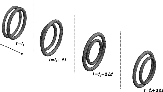
Fig. 1. Interaction between a pair of axially aligned vortex rings showing their mutually induced leap-frogging motion (schematic).
Particle image velocimetry (PIV) has shown (Ref. 7) that the global geometry of the flow field at the onset of wake breakdown is highly transient, or, in other words, that the geometry of the wake at any partic-ular instant may be quite different to the geometry of the mean flow. At the onset of the VRS, where the descent rate is typically approximately half of the rotor downwash velocity, PIV shows the wake to swap inter-mittently between two forms—one of which is similar to the structure found at hover and another that resembles a ring, or toroid, of vorticity that bundles up beneath the rotor plane. As the descent rate is increased to near the mean rotor downwash velocity, the wake structure becomes more inclined to remain in the second mode and thus the rotor appears to be engulfed in the recirculating flow that characterizes the VRS. The unsteadiness of this recirculating flow arises from a recurrent, aperiodic, and spatially nonuniform process in which the vorticity within the ring builds up over a number of rotor revolutions and is then ejected into the free stream (Refs. 3,4,8,9). In addition to the highly transient blade loading, the concentration of vorticity near to the rotor during the on-set of VRS (Ref. 10) causes a reduction in rotor thrust if the collective pitch setting is held constant (Refs. 5,11), or equivalently an increase in the power required by the rotor if the thrust is held constant (Ref. 12). This effect, known as thrust settling or settling with power, depending on context, persists until the descent rate becomes large enough to push the wake above the rotor, though the rotor may still be within the VRS. Cessation of this flow regime comes about when the descent rate is so high that the recirculating flow near the rotor can no longer be sustained, and the orderly structure of the wake near to the rotor is reestablished (Refs. 10,13).
The behavior of a rotor operating within a field of concentrated and highly mobile vortical structures is strongly nonlinear. The physics of the transmission and growth of disturbances through the rotor wake is complicated by the long-range nature of the interactions between vortex filaments and the coupling between the dynamics of the wake and the loading that is produced on the rotor. Indeed, the complexity of the VRS is borne out by the varied, counterintuitive, and conflicting nature of several published reports, as revealed in Johnson’s survey of the published VRS literature (Ref. 14).
Significant insight into the physics of the VRS can be obtained by considering the dynamics of the wake in terms of the nonlinear, time-varying, and mutually induced motions of the coherent vortical structures within the flow surrounding the rotor. The dynamics of the helical tip-vortex, because of its high relative strength, dominates the behavior of
the wake (although the in-board sheet and root vortex appear to be the source of many of the subtle differences in behavior between different rotor systems). Given the many practical difficulties in performing a fully nonlinear analysis, insight into the inherent dynamics of these helical vortex structures has traditionally been sought via a linearization of the system. Widnall’s analysis of the linear stability of helical vortex filaments revealed the existence of three modes of instability (Ref. 1). Small geometric perturbations to the helix will grow either through a mode with wavelength equal to just a few core-diameters, or as a very long wave that extends over several helix diameters. A third growth mode, which Widnall termed the “mutual-inductance” mode, manifests as an interaction between immediately adjacent turns of the helix. This third mode resembles, in the linear, small excursion range, the “leap-frogging” phenomenon that is characteristic of the interaction of two or more axially aligned vortex loops, as illustrated in Fig. 1.
The first and third modes of instability have been observed in the wake of a rotor. Leishman et al. (Ref. 2) analyzed the helical tip-vortex system generated by a helicopter rotor and implicated the mutual-inductance instability, or “vortex pairing” mode, as the major cause of VRS initiation. This was because, in their free-wake simulations, this instability appeared to give rise to a “bundling” of vortex filaments into rings that move gradually upward toward the rotor as the rotor descent rate is increased immediately preceding the onset of the VRS.
Widnall and Leishman et al. all showed how small perturbations to the geometry of long helical vortex systems can grow exponentially. Di-rect application of these results to understanding the onset of the VRS is not strictly appropriate, however, due to the underlying linearity of the analysis. Linear analysis is valid only for disturbances with small amplitude and provides no clear information on the actual kinematics of the vortical filaments outside the range of small excursions. In particular, the growth of perturbations to the wake structure cannot be limitless, yet no information can be provided by a linear analysis on the geometry that the disorganized filaments of the wake might adopt after finite time. For instance, the mutual induction mode may look like the leap-frogging motion of coaxial vortex rings2in the linear range, but, for any
distur-bance with finite amplitude, the topological constraint that is imposed
2Henceforth, the term “leap frogging” will refer to the axial overlapping of axially
Fig. 2. A helix becoming entangled by the action of pairing of its turns (schematic).
by Kelvin’s laws on the helical structure of the wake means that the actual dynamics cannot be entirely equivalent to leap frogging. Indeed, it is noteworthy that this basic fact is missed in some of the more sim-plistic descriptions of the onset of the VRS that have been published, especially those where the behavior of the wake is represented in terms of the dynamics of a stack of vortex rings (Ref. 15). As will be shown later in the present work, the topological constraint that is imposed by the helical rather than ringlike nature of the vortex filaments results in entanglement and significant distortion of the helix as the leap-frogging interaction between neighboring turns reaches appreciable amplitude, as depicted in Fig. 2.
The aim of the present work is thus to study the VRS from beyond the point where a linear stability analysis ceases to provide insight. This paper will describe in detail, both qualitatively and quantitatively, the structure and kinematics of the rotor wake during descending flight and aims to contribute to an understanding of the vortex dynamics that leads to the onset of the VRS and the associated structural changes within the rotor wake. It will be shown that the principal kinematic mechanism that leads to wake breakdown and to the eventual onset of VRS, and indeed to the maintenance of the wake within the toroidal form that is characteristic of the VRS, is the nonlinear growth of the pairing instability in the presence of the topological constraints on the motion of the vortical filaments in the wake, and the eventual reorientation of these filaments from lying principally parallel, to having a significant component normal to the plane of the rotor. As such, the paper is intended to complement those works that have tended to focus more strongly on the various effects of the VRS wake on the performance of the rotor (Refs. 11,12,16).
To avoid later confusion, it is worthwhile at the outset to define some of the terminology that is common to both this paper and to much of VRS literature that exists to date—in particular, the terms “VRS onset” and “wake breakdown.” The meaning of such phrases has been blurred by the slightly different context in which fluid dynamicists and performance specialists view the VRS. In this paper, the term VRS onset will be used to describe that particular stage during descent when the vorticity in the wake first adopts a persistent toroidal form near to the plane of the rotor. In contrast, wake breakdown will be used to describe the process whereby all or part of the wake loses its organized helical structure and adopts some other less coherent geometry.
High-Resolution Wake Modeling
A series of high-resolution computational simulations of a rotor en-tering the VRS were conducted using Brown’s vorticity transport model (VTM) as described in Refs. 17 and 18. The VTM calculates the evolution through time of the vorticity distribution in the flow as governed by the vorticity–velocity form of the incompressible Navier–Stokes equation,
∂ω
∂t +u· ∇ω−ω· ∇u=S+ν∇
2ω (1)
Note that the flow field that is modeled is three dimensional, and be-cause the evolution of the vorticity within the computational domain is constrained only by Kelvin’s laws, the calculation is entirely free of the artificial embellishments that have had to be introduced into some other models to allow them to capture some semblance of VRS onset (Ref. 15).
Of particular interest in the present work is the last term on the left-hand side of this equation—this “stretching” term rotates and dilates individual vortex filaments within the flow. The effect of dilation on the vortical structure of the rotor wake has been dealt with comprehensively by Ananthan et al. (Ref. 19). They introduced a stretching model that modified the diameter of the vortex core and the strength per unit length of the vortices as they stretched, in accordance with the principle of conservation of circulation. Using this model, they showed that dilation of vortex filaments is more prevalent in the VRS than in the flow field of a hovering rotor. In the present paper, the importance of vortexrotation
on the structure of the wake in the VRS is exposed.
The vorticity generated on the rotor blades is introduced to the flow field by the sourceS, which can be defined in terms of the vorticity that is shed and trailed from the blades of the rotor as
S= −d
dtωb+ub∇ ·ωb (2)
whereωbis the bound vorticity on the blades.
A regularized version of the Biot–Savart equation is employed to cou-ple the vorticity in the flow to the velocity field. The vorticity is advected through the three-dimensional (3D) computational space surrounding the rotor using the weighted average-flux scheme of Toro (Ref. 20). This approach explicitly conserves the vorticity as it advects from one compu-tational cell to another and allows the spatial localization of the vortical structures in the wake to be maintained for long computational times. The VTM is thus particularly well suited to computations of the VRS where the flow field is characterized by the long-term persistence of the vorticity distribution near to the rotor.
Simplification of the rotor model
this feature of the VRS most clearly, the aerodynamic coupling between rotor and wake was removed in all the simulations described in this paper. This was done by prescribing the bound vorticity,ωb, to be uniformly
distributed along the length of the blade, and to be constant for the entire duration of the simulation. As described by Eq. (2), this constraint then causes the blade to generate a wake that consists solely of a tip vortex and a root vortex. These vortices have the same strength at their points of origin on the blade surface and, when taken together with the bound and starting vortices, allow a particularly simple vorticity field to be produced by the rotor that satisfies Kelvin’s topological constraint in both local and global sense. The magnitude of the bound vorticity on the blade was prescribed so that the rotor would generate a thrust coefficient of 0.005 when in hover.
VRS Simulations
Two different high-resolution computational simulations of this rotor during the onset of the VRS were performed using the VTM. In the first simulation presented in this paper, the VRS was approached from high-speed descent with the rotor initially within the windmill brake state. The descent rate within the VRS in this case was kept high enough for the circulatory flow to remain above the plane of the rotor. The vortex kinematics of this high-speed VRS is contrasted with the evolution of the wake in a simulation, presented later in this paper, of the far more complex situation when the VRS is approached from hover and the descent rate is kept low enough so that the vortex toroid remains below the rotor.
High-Speed Vortex Ring State
Figures 3–5 show the development of the simplified rotor wake as the rotor was decelerated from the windmill brake state, where the thrust-normalized descent velocity,μz, was−2.1, into a regime that is deep
within the VRS. This regime was approached via a gradual reduction of the descent velocity, over a period of 10 rotor revolutions, to a normalized descent velocityμz= −0.9. This descent speed was then held constant
for the remainder of the simulation. A computational grid with 62.5 computational cells per blade radius was selected so that the evolution of individual tip-vortex filaments would be resolved even when the rotor was operated deep within the VRS.
[image:5.612.355.547.68.248.2]Visualizations of the simulated flow field show clearly the compli-cated vortex dynamics that lead to the initiation of the VRS when ap-proached from the windmill brake state (WBS). As the descent speed is reduced, the two or so helical filaments that are closest to the rotor expand radially outward. These filaments induce those filaments above them to contract radially (Fig. 4)—this reduction in diameter increases the self-induced convection speed of these filaments thus causing them to move downward against the free stream. Initially, this quasi-symmetrical motion resembles the leap-frogging process shown in Fig. 1, with the necessary radial expansion and compression of the axially compacted helical turns being evident. Soon afterward, though, larger, out-of-plane motions begin to occur; the disturbances in the vorticity field start to grow nonlinearly, and degeneration of the wake into full VRS ensues (Fig. 5). Once in the VRS, three, though sometimes just two, and occasionally as many as four, coherent turns of the helical vortex can be seen to persist just above the rotor plane, showing that the nonlinear growth of pertur-bations takes a finite, but somewhat variable time to manifest within the wake. Without the existence of these coherent filaments lying parallel to the rotor plane, though, a ring-like recirculation of the flow, the existence of which is almost universally taken to indicate the existence of VRS conditions on the rotor, would almost certainly not arise. Importantly, this set of ring-like vortex filaments accounts for the increased inflow produced by the wake of a rotor operating in VRS.
[image:5.612.336.562.294.486.2]Fig. 3. The wake of the simplified rotor in WBS (isosurface of vorticity magnitude).
[image:5.612.326.571.534.718.2]Fig. 4. The wake of the simplified rotor entering the VRS from the WBS (isosurface of vorticity magnitude).
As the descent speed of the rotor becomes constant, a repeating pattern of behavior emerges, although the flow field is so unsteady and interac-tional that the vortex kinematics often deviates quite significantly from the mean behavior. The helical vortex system approximates a stack of closely spaced and axially aligned vortex rings that has been compressed longitudinally by the resultant velocity field—this structure might be termed the “base flow” of the vortex ring state. The ring-like structures comprising the base flow, generally three in this particular simulation, evolve in a way that is approximately analogous to the evolution of three axially aligned vortex rings in an otherwise quiescent flow field. The leading ring is forced to expand and slow down by the velocity field of the two rings behind, as they accelerate toward it. The second, middle ring also expands by the action of the third, trailing ring that reduces in radius as it moves through the middle ring on its way toward and through the leading ring. The leading ring thus becomes the middle ring and the middle ring, which has since become the trailing ring in the stack, is compressed and accelerated once more down toward the leading ring, passing through the middle ring as it does so.
With this concept of a VRS base flow in mind, the dominant vortex motions that act to disrupt it can be described more fully. First, in the absence of the hydrodynamic instabilities that exist in the real flow, and in the absence of viscosity, this leap-frogging process would continue unabated (Ref. 21) and the number of coherent vortex turns in the base flow would increase until the structure achieved sufficient self-induced velocity to move down past the rotor plane, resulting possibly in the reestablishment of the orderly helical structure of the wake. Indeed, this behavior was alluded to by Brand et al. (Ref. 15), and will be discussed further later in this paper. With the rotor in the VRS, however, the free-stream flow opposes the natural convection of the stack of ring-like vortex filaments and effectively traps it near the plane of the rotor. An observer on the rotor would see the leap-frogging process described earlier as essentially a recirculation of the filaments within the stack.
Second, the base flow is distorted by the action of flow instabili-ties. These instabilities cause small perturbations to the geometry of the compacted vortex filaments within the base flow of the VRS to grow in a manner governed by the pairing instability of helical vortex systems and the short-wave instability that is common to both helical and ring vortices. In the simulation, as a new tip-vortex filament was produced by the rotor it immediately began to expand radially and to move upward as a result of the velocity field that was induced by the ring-like vortex filaments above it. As the filament traveled to the top of the stack of rings, it developed irregularities in its form that seemed to be largely due to the action of the short-wave instability. As the disturbances to the filament grew, its influence on the tightly packed helical turns above and below appeared to increase too, the shape and trajectory of those filaments also being modified as a result. This interaction seemed to vary sufficiently in detail around the circumference of each vortex filament so that no two helical turns of the base flow developed and distorted in exactly the same way as they made their way upward toward the top of the stack of recirculating vorticity.
Each turn of the tip vortex was usually distorted quite considerably from its original, helical shape by the time that it had made its way to the top of the recirculatory base flow. In most cases, the ring was then ad-vected back down into the stack as if it were part of the unperturbed base flow. The irregularities in their shape cause the filaments to be convected back down into the stack unevenly, however. The nonuniform radial ve-locity near the top edge of the base flow exacerbates any deviations from ring-like geometry and causes long sections of the vortex filament to be reoriented very rapidly from lying almost parallel to the rotor plane to an almost perpendicular orientation relative to the rotor plane. An example of one of these large-angle excursions in progress is shown in Fig. 6 where the orderly configuration of the first three rings in the stack is in
strong contrast to the geometry of the strongly reoriented fourth ring. The extensive deformation to the vortex filament that is shown in this figure begins as a large-radius “hairpin”-like structure, such as that shown in Fig. 7.
Third, the topological difference between a set of rings and a compacted helix further divorces the dynamics of the wake of a rotor in VRS from that of a stack of coaxial rings—as illustrated in Fig. 2, the turns of a helix cannot pass through one another without becoming entangled. An example of the possible extent of such entanglement is shown in Fig. 8. The legs of these hairpin-like structures, that is, the almost-vertical sections of the once ring-like vortices, become wrapped in spiral fashion around the core of the toroidal base flow. This process leads very quickly to the complete destruction of the original structure of the majority of the vortex loops once they reach a certain, finite age. The combination of multiple such events yields the rather intricate, radial, spoke-like structure to the wake shown in this figure. It is this process of tip-vortex generation and eventual destruction via the action of vortex instability that appears to allow the flow within the VRS to attain a state of quasi-equilibrium. Put another way, the instabilities act ultimately to limit the number of coherent ring-like vortices in the toroidal wake. Indeed, Brand et al. (Ref. 15) found they had to account for this effect by prescribing a finite “life” to each vortex ring in their simple model, else their VRS wake would not develop realistically.
The Importance of Filament Reorientation
Much has been made hitherto of the reorientation of the vortex fil-aments, or more precisely, the local conversion of vorticity oriented parallel to the rotor plane to vorticity oriented perpendicular to the rotor plane. This is partly because this reorientation process is the nonlinear, large-amplitude continuation of the development of the linear modes of instability that were highlighted by Widnall (Ref. 1) and Leishman et al. (Ref. 2), and thus the observations made earlier contribute usefully to our understanding of the eventual fate of vortex systems that are subject to these instabilities. Furthermore, these reorientations are not just passive, inconsequential events; filament rotation has a profound effect on the velocity field that is induced by the rotor. This is because the induction of inflow through the rotor is dependent only on the component of vor-ticity that lies coplanar with the rotor disk. This follows simply from the fact that the velocity that is induced by a vortex element is perpendicular to its axis of rotation. Filament reorientation is thus an important and influential process within the VRS since it removes from the flow a sig-nificant quantity of vorticity that would otherwise contribute to a steady increase in the inflow through the rotor. As Brand et al. found (Ref. 15), in the absence of this effect, the wake is eventually propelled below the rotor and out of the VRS regime (hence their need to impose an artificial restriction upon the number of ring vortices that was allowed within their axisymmetric computational domain).
An indication of the extent to which filament reorientation takes place within the VRS can be inferred from Fig. 9. The images show a decomposition of the vorticity field into the components of vorticity that are aligned parallel to the disk plane [Fig. 9(a)] and the component of vorticity that is aligned normal to the rotor [Fig. 9(b)]. The same value of vorticity magnitude was used to create the isosurfaces in both figures to allow a comparison of the relative contributions of each component to the overall vorticity in the flow. So, as the components of vorticity
ωx and ωy oriented parallel to the rotor plane are partially converted
into vorticityωzoriented normal to the rotor plane, the local component
Fig. 6. Snapshot of the wake structure within high-speed VRS showing the disruption to the wake as a result of large-amplitude reorientation of the tip vortex (isosurface of vorticity magnitude).
[image:7.612.148.471.496.711.2]Fig. 8. A view from beneath the rotor showing how reorientated vortex filaments are wrapped around the core of the ring-like VRS base flow (isosurface of vorticity magnitude).
rotor wake when in the VRS. This observation has particularly important consequences for the interpretation of the simulation to be presented later in this paper, where reorientation of vortex filaments is implicated as the prime factor leading to the collapse of the ostensibly tubular wake of the rotor, when in hover, into the toroidal structure that is characteristic of the VRS.
Ejection of Vorticity from the Toroid
A final consequence of the reorientation process described earlier, as far as the tip vortices are concerned, is that the distorted vortex structures that are produced by this process do not remain indefinitely within the toroidal base flow. Figure 5 shows the existence of a continuous stream of vorticity into the flow downstream of the rotor that originates from just above the toroid. This stream is roughly coaxial with the rotor and has a diameter that is approximately two thirds of that of the rotor.
Several previous studies have commented on the existence of a central upflow through the rotor disk when in the VRS (see Refs. 7 and 16). The existence of this upflow is likely to be dependent on both the configuration of the rotor and its descent speed, however (Ref. 16). There is indeed some evidence for the existence of an upward flow through the root of the particular rotor that was simulated in this study. The general trajectory of the root vortices is indicated in Fig. 10 where it is seen that, in this particular case, these vortices are initially convected slightly upward and away from the disk plane before being swept radially outward, and finally downward into the recirculating base flow that is associated with the tip-vortex system.
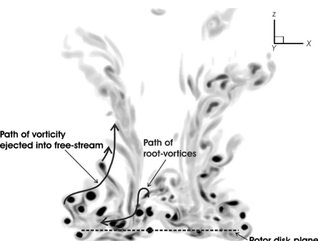
To emphasize this point, Fig. 11 shows a set of particle paths through the time-averaged flow around a rotor (of somewhat different geometry to that simulated in this study, though) that is descending at a similar normalized speed (μz= −1.0). This figure shows the existence, in the
mean, of an extended, toroidal, recirculating region of flow around the tips of the rotor that is generated by the structured, ring-like vortices within the base flow. This recirculating flow gives way, some distance outboard, to an upward-directed flow. Shown in Fig. 10 is the path that in general is
Fig. 9. Vorticity field of the wake in VRS, decomposed into compo-nents normal and parallel to the disk plane.
taken by the vorticity that is ejected up through the central stream. Indeed, the vorticity in the ejection stream appears to be comprised entirely of those elements of the disintegrating, toroidal base flow that move far enough toward the periphery of the recirculating region to be entrained into the outer flow instead of being convected back down into the toroidal base flow.
[image:8.612.42.291.71.297.2]Fig. 10. Paths followed by vorticity (a) in the ejection stream and (b) originating at the blade root.
Fig. 11. Particle paths through the time-averaged flow generated by a rotor in high-speed VRS (μz = −1.0, VTM simulation).
kinematics underlying this process to be examined in greater detail than has been possible in experiments, to date.
Figure 12 shows how a breakaway event usually follows the coin-cidental, near simultaneous reorientation of neighboring parts of two adjacent vortex loops within the ring-like base flow. The first image in Fig. 12 shows a two-dimensional (2D) contour plot of vorticity on a plane that passes through the rotor hub. Captured in the plot at top left is a sectional view through the wake just prior to an ejection event as two vortex filaments, marked “a” and “b,” begin to interact more strongly than is normally the case. Highly distorted sections of the two loops that are left near the top of the stack do not necessarily follow the normal
recirculating trajectory that would take them back down into the toroidal flow, or even into the central ejection stream. Instead, on occasion, they begin to orbit around one another. The 3D image at bottom left reveals the structure of the two coorbiting filaments in more detail. A small number of rotor revolutions then generally elapse before the intertwined pair of filaments suddenly eject themselves almost straight upward from the top of the toroid and away into the free stream.
The violence of the ejection is most likely a consequence of the high mutually induced velocity of the filaments involved in the process. The set of images at right shows the structure of the wake at this time, three rotor revolutions after the first set of images were taken. At this stage of the interaction process, filament “b” has been ejected into the flow downstream of the rotor. The 3D image at bottom right shows how the two coorbiting filaments deform into a tight hairpin-like structure during the ejection process. These large-scale ejections of vorticity into the flow downstream of the rotor tend to disrupt the normal evolution of the stack of coherent vortex rings within the base flow for several rotor revolutions by causing subsequent turns of the wake to follow a similar process. Eventually, though, some semblance of order is reestablished following the creation of fresh vorticity at the base of the stack by the passage of the rotor blade beneath the disturbed region.
A survey of the wake structure
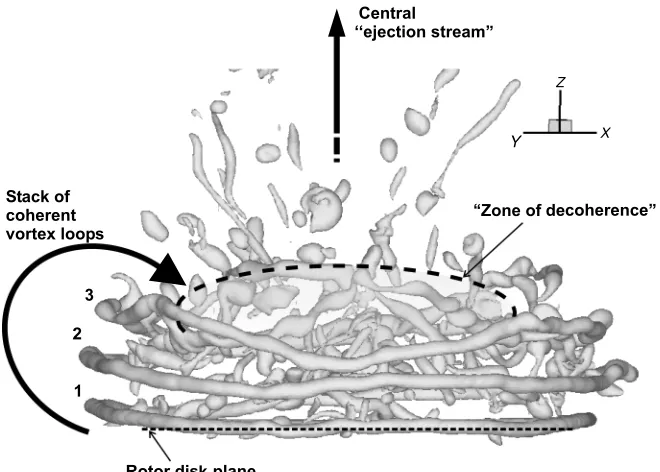
These observations, when taken together, reveal that the wake of the rotor in high-speed VRS, i.e. when the main body of the wake lies above the rotor, even though highly disordered in part, does still have appreciable structure. By way of summary, Fig. 13 shows the stack of coherent, recirculating, and axially compacted helical vortex filaments, the region in the center of the wake where the helical vortex structures lose their form under the action of the velocity gradients in the flow field, and, finally, the almost continuous stream of ejected vorticity up the centerline of the wake that together characterizes the flow field of the rotor when in high-speed VRS.
Fig. 12. 2D and 3D images of the rotor wake in VRS showing the initiation of a large-scale vortex breakaway.
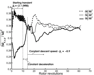
[image:10.612.142.472.475.711.2]Fig. 14. Variation of the contribution of each vortex component to the overall vorticity in the flow field.
during the transition from WBS to VRS can be exposed by a statistical survey of the orientation angles with respect to the rotor plane that the vortex filaments adopt within the wake. Shown in Fig. 14 is the variation with time of the relative contribution of each component of the vorticity to the overall vorticity within the volume encompassing the entire diameter of the rotor and extending from the rotor plane to a rotor radius above the disk plane.
For the first 10 rotor revolutions of the simulation, the descent speed was held constant with the rotor in the WBS. Figure 14 shows the contri-bution of the vorticityωznormal to the disk plane to the overall vorticity
in this phase of the simulation, at approximately 27% to be somewhat lower than that of the combined contributions of the two vorticity compo-nentsωxandωyparallel to the disk plane. Note that this figure includes a
significant contribution from the tip vorticity as well as from the equally strong though more steeply inclined root vorticity. The rotor was then decelerated into the VRS. The figure shows the contributions ofωxand
ωyto fall slightly as a result, but the contribution ofωzto the overall
vor-ticity to rise sharply. This is evidence of the increasing effectiveness of the wake instability in inducing reorientation of vortex filaments during the deceleration. Just after the point where the deceleration ends there is a period of transients while the wake settles and the VRS behavior devel-ops. Once the VRS has fully developed (between revolutions 40 and 45), the ultimate contribution of the vorticity normal to the disk plane to the total vorticity is approximately equal to the contributions made by the two components parallel to the disk plane, although this ratio fluctuates somewhat due to the unsteadiness of the flow field. In other words, while the majority of the vortex filaments within the wake during the fully developed VRS remain coplanar with the rotor disk, roughly one third, rather than one quarter as in the WBS, of the total vorticity near the rotor is made up of vorticity that does not contribute to the generation of inflow through the system.
To extend this examination of how the orientation of the vortex fila-ments changes as the rotor moves from the WBS to the VRS, the statistical spread of orientation angles with respect to the rotor disk plane, given by
γ=sin−1(ω
z/|ω|), that is adopted by the vortical filaments in the wake
was calculated at different times during the simulation. Figure 15 shows the frequency of occurrence, denoted byζ, of vortex filaments oriented within 5◦angular intervals between−90◦and 90◦, divided by the total number of occurrences,n, in the overall range. The squareroot of the frequency of occurrence is plotted simply to improve the clarity of the presentation. Each graph in the figure compares the spread of angles after 10 rotor revolutions (in the WBS) and after 40 and 50 rotor revolutions (during the VRS). The two plots differ by the minimum magnitude of vorticity that is included in the count. This “filtering” of the data was conducted to understand how the orientations of the strong, coherent structures differ from that of the fog of low-level vorticity in the flow field.
Fig. 15. Statistical spread of vortex filament orientations with respect to the horizontal in WBS and high-speed VRS.
A similar analysis of the wake with the rotor in the VRS (i.e., after 40 rotor revolutions) shows a general decrease in the number of filaments aligned parallel to the disk and a substantial increase in the number of filaments aligned more obliquely to the rotor plane compared to the situ-ation in the WBS. Within the VRS, however, the considerable mixing of the root-vortex and tip-vortex filaments renders invalid the clear distinc-tion between the physical source of filaments with positive and negative orientation angles that can be made in the WBS. The apparent symmetry between the spread of filaments with positive and negative orientation angles within the VRS, and the relative breadth of the distribution of filament orientations within the wake, is extremely interesting, since it is entirely consistent with the predominance of a process within the wake whereby the vortex filaments are forced to undergo continuous end-over-end rotation. As described earlier, the reorientation process transforms a source of vortex filaments with near-zero orientation angles (the vor-ticity in the base flow) into filaments with larger orientation angles with respect to the disk plane. There is no inherent property of the vortex kinematics that precludes, locally, the reverse process, however—that is,
the conversion of filaments with larger orientation angles back into fila-ments with smaller orientation angles with respect to the disk plane. The distinct, but near-linear tail-off in the frequency of vortex filaments with larger orientation angles with respect to the rotor plane is consistent, in fact, with the near-equilibrium of the forward and reverse processes. Cer-tainly, comparing the frequency distributions that are obtained at 40 and 50 rotor revolutions into the simulation shows that the preferred distri-bution of vortex filament orientations remains a fairly constant feature of the structure of the rotor wake when in the VRS and supports this notion of at least a statistical equilibrium within the flow. The much stronger tail-off in the frequency of filaments with the highest orientation angles is consistent with the structure presented in Fig. 9, which shows filaments with almost normal orientation to the rotor plane to predominate in the stream of vorticity that has been ejected from the toroidal, VRS base flow and captured by the free stream.
Kinematics and Structure of the Hover Wake
The kinematics of the vortical flow field that lead to the onset of the vortex ring state when the descent commences from hover instead of WBS was also investigated using the simplified rotor described earlier. In this simulation however, the number of computational cells per blade span was reduced to 50, since exploratory runs showed this to be sufficient to resolve clearly the dominant vortical structures within the flow. The trajectory of the rotor comprised an initial 20 rotor revolutions with the rotor in hover to allow sufficient time for a fully developed wake to form. The hover phase was followed by an accelerated descent, over a duration of 28 rotor revolutions, ending with the rotor at a normalized descent rate
μz = −0.45. At this descent rate, the rotor was in a regime considered
to be just within the flight envelope that encompasses the VRS. Twenty-three rotor revolutions were then captured with the rotor descent speed held constant at this value.
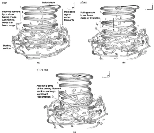
Visualizations of the 3D structure of the vorticity field that is generated by the rotor in hover, as presented in Fig. 16, show the clear influence on the geometry of the rotor wake of both the vortex-pairing instability and the short-wave instability that are known to influence very strongly the kinematics of helical vortex filaments (Refs. 1,2) as described earlier in this paper. The manner in which the ultimately nonlinear manifestation of the pairing mode diverges from its initial, linear, leap-frogging, form is also clearly evident. The figure shows the evolution of the wake of the hovering rotor, starting from the 15th revolution of the simulation, i.e. from whence a reasonably well-developed wake has been established beneath the rotor.
Fig. 16. Example of the nonlinear vortex pairing/reorientation mode occurring in the wake of a hovering rotor.
the wake by the helical, rather than ring-like, topology of the tip vortex, as described earlier.
Figure 16(c) shows the geometry of the wake a further three quarters of a rotor revolution on from the geometry shown in Fig. 16(b). In this final figure in the sequence, the perturbation to the geometry of the originally helical vortex segments has proceeded well into the nonlinear regime, to the extent that these segments of the tip vortex have begun to lose coherence both through their own, mutual interaction and through interactions with other nearby elements of the wake. Indeed, the products of earlier such large-scale disruptions to the structure of parts of the tip vortex can be seen in the far wake. This process, whereby small perturbations to the structure of the vortex are amplified through the nonlinear action of this pairing/reorientation mechanism, is continuous and repetitive and results in the almost total annihilation of any structure to the vorticity distribution in the far wake of the rotor.
Figure 17 shows the vorticity field in the wake of the hovering rotor at the end of its 20th revolution. In this pair of images, the vorticity in the wake has been decomposed into its components parallel to the disk plane [Fig. 17(a)], and its component normal to the disk plane [Fig. 17(b)]
in similar fashion to the data presented earlier in Fig. 9 for the rotor in high-speed VRS. A comparison of the two images shows significant rotation of the helical tip vortex into a disk-normal orientation by the time the tip vortex has aged by several rotor turns. Although there is evidence in Fig. 17(b) for reorientation on a much smaller length scale as a result of the influence of the short-wave mode of instability, it is primarily the pairing mode that is responsible for the loss of coherence of the vortical structures in the wake. It is thus eminently arguable that it is the vortex kinematics of the wake, in particular the reorientation of vortex filaments, rather than an inherently viscous mechanism that is responsible for the structural decay and consequent truncation of the wake that has been observed experimentally (Ref. 7).
Fig. 17. Vorticity field of the wake in hover, decomposed into compo-nents normal and parallel to the disk plane.
normalized by the mean rotor inflow, λh. The axes are scaled by the
rotor radius. The image on the right-hand side of the figure shows an isosurface of vorticity in the wake, with the contour level of the surface set to expose the strongest vortical structures in the wake. When taken together, these images of the instantaneous flow field near the rotor show clearly the influence of filament reorientation on the downwash that is induced within the wake. Indeed, at distances greater than approximately 2Rbelow the rotor, the magnitude of the velocity of the downward flow is seen to reduce considerably compared to that closer to the rotor. This
reduction coincides with the end of the coherent, structured region of the vorticity field and the degeneration of the helical tip-vortex into a system of strongly interfering vortex filaments that have undergone significant pairing and reorientation. Even further below the rotor, the natural in-stability of the wake results in the destruction of most of the coherent vortical structure that was responsible for producing some proportion of the downwash within the wake. The obvious consequence of this reduc-tion in downwash is the very low rate of vorticity transport in the far field and hence the observed congregation of disorganized, fragmented vortical structures some distance further below the rotor.
That these observations are not just a fluke, perhaps resulting from the examination of just one realization of the instantaneous flow field near the rotor, is easily demonstrated by considering the mean effect of a long sequence of such instantaneous realizations of the flow on the global properties of the wake. Figure 18(b) shows the vorticity and the associated induced velocity field, on a 2D slice containing the rotational axis of the rotor, after averaging the flow field of the hovering rotor over 120 revolutions. Comparison of Fig. 18(b) with Fig. 18(a) emphasizes the important fact that the apparent decay of the strength of the mean wake with distance below the rotor results fundamentally from the increasingly irregular motion of the vorticity within the tip-vortices as they move axially away from the rotor, and hence the disappearnce from the mean of their contribution to the flow field.3
Low-Speed VRS
As described earlier, the wake is effectively truncated by the loss of coherence in the turns of its helical tip vortices that occurs several rotor radii downstream of the disk plane. Thus it is the rate of growth of the fluid instabilities within the system that governs the length of the wake for a given inflow through the rotor. If the rotor thus descends slowly enough, the helical, hover-like form of the wake can still be maintained for some distance below the rotor. All else being equal, the pitch of the helical wake in low-speed descent is reduced compared to the case in hover, though. Simplistically, this is because, in descending flight, the tip vortices travel a reduced distance during a single revolution of the rotor, under the competing influences of their self-induced velocity and the opposing free stream, compared to when the rotor is in hover. Leishman et al. (Ref. 2) showed that the distance between the vortex filaments was the dominant factor governing the growth rate of perturbations (for a given vortex strength). Thus, as the rotor descends, the pairing that leads to reorientation and the ultimate destruction of any coherence to the structure of the wake some distance below the rotor, occurs at an earlier tip-vortex age than it does with the rotor in hover. Effective truncation of the wake thus occurs closer to the rotor than it would if this dependency did not exist. This can be seen clearly by comparing the decomposition of the vorticity into components parallel and normal to the disk plane for the rotor in hover, shown in Fig. 17, with a similar decomposition of the vorticity generated by the rotor in slow descent as shown in Fig. 19.
Some short time after the descent speed of the rotor became constant in the simulation (atμz= −0.45 in this simulation), the tubular shape of
the wake was no longer in evidence and the rotor had entered the vortex ring state as shown in Fig. 20. The figure shows two images of the vor-ticity field, some 20 rotor revolutions after the descent speed had become constant. The first image shows an isosurface of the vorticity distribution in the wake with the contour level used to generate the surface set very
3Indeed, this interpretation of the results presented here has recently been
Fig. 18. (a) Isosurface of the instantaneous vorticity field (right) of a hovering, single-bladed rotor. The velocity field induced by the vorticity field is shown (left) as contours of downward flow velocity normalized by the mean rotor inflow,λh. (b) 2D plots of mean contours of vorticity
and the associated induced downward flow in the velocity field. The mean fields were constructed from 240 snapshots over 120 rotor revolutions. The velocity field has been scaled with the mean inflow at hover,λh.
low so that much of the weak vortical structure is exposed. The wake appears to consist mostly of fragmented vortex filaments, orientated or-thogonally to the core of a large toroid of vorticity about which they recirculate. The second image, again showing an isosurface of vorticity, but with the surface value set high enough to retain only the strongest features of the vorticity field, shows that, beneath the weak, fragmented layer of vorticity, the wake consists of a highly compacted helix com-prising just two definite, coherent, turns of the tip vortex. A third turn is still evident, though it has been deformed significantly by the highly unsteady and nonuniform local velocity field. As time progresses, the individual turns of the helix are transformed into other less recognizable structures which are then entrained into the recirculating flow around the vortical toroid. The results of this process can be seen very clearly in Fig. 20(a). Long-term observations show that little vorticity appears to escape from the recirculatory current, however, unless it happens to be convected sufficiently far out from the circumference of the toroid so that it is captured by the free stream and drawn upward away above the rotor. Indeed, the large-scale ejections of vorticity that are a distinct characteristic of the high-speed VRS appear to be absent in low-speed VRS.
A survey of the wake structure
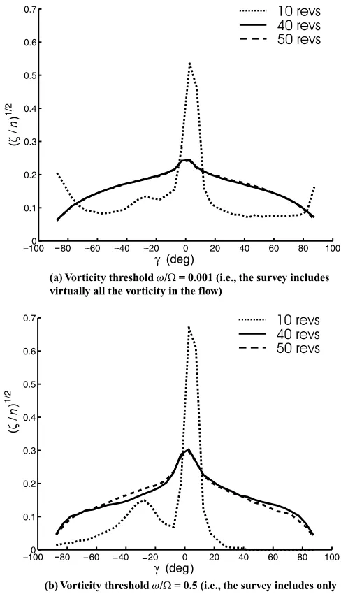
A survey of the orientation angles adopted by the vortex filaments in the wake, as shown in Fig. 21, reveals that the underlying structure to the flow fields of the low- and high-speed VRS is very similar despite the subtle differences in their underlying kinematics. The figure shows the frequency of occurrence of vortex filaments that are oriented at given angleγ to the rotor plane, within a cylindrical volume that is coaxial with the rotor and that has a width of four rotor radii. In the vertical direction, the volume extends one rotor radius both below and above the rotor disk—this volume is sufficiently large to capture all the near-field vorticity in the flow. The curves represent the spread of filament orientation angles at 20 rotor revolutions (i.e., at the end of the hover phase), after 32 rotor revolutions (i.e., with the rotor in low-speed, pre-VRS descent atμz = −0.2), and after 60 rotor revolutions (i.e., 12
rotor revolutions post cessation of acceleration, with the rotor in
low-speed VRS atμz= −0.45). The distribution of filament orientations at
all descent rates shows a distinct peak for orientation angles within the interval−5◦to 0◦; this peak is associated with the tip vortex of the rotor. The reduction in the height of this peak as the descent rate of the rotor is increased is clear evidence for the increasing loss of coherence of the tip vortex structure as VRS is approached. The qualitatively very similar distribution of orientations that is adopted by the vortex filaments both in low-speed VRS and in high-speed VRS [see Fig. 15(c)] shows that the influence of the instabilities in both systems is to yield fundamentally the same outcome in terms of the resultant structure of the vorticity within the rotor wake.
The vortical wake in low-speed VRS, then, consists of a compacted helix comprising just a few closely spaced turns, each of which is short lived as a result of the growth of the many and seemingly random pertur-bations imposed upon it by the highly nonuniform velocity field near the rotor. The geometry of the helix exhibits numerous manifestations of the action of the short-wave instability; the resultant perturbations can reach appreciable amplitude as early on as just one quarter of a revolution fol-lowing the generation of the affected segment of the wake. Significantly, though, the wake in low-speed VRS shows scant evidence of the pairing of sections of adjacent vortex turns and the accompanying large-scale reorientation of vorticity that is the dominant mode of relative filament motion in the flow field of a hovering rotor, or indeed in the wake at high-speed VRS.
Just as in high-speed VRS, the dominant motion in low-speed VRS is still similar to that of an axially compressed stack of axially aligned, recirculating vortex rings, save for the modifications to that flow that result from the underlying helical, rather than ring-like topology of the rotor wake. Unlike in the high-speed VRS, however, each newly gener-ated tip-vortex filament finds itself to be the trailing loop, rather than the
[image:15.612.45.579.72.273.2]to the induced flow. At this juncture, the direction of travel of the leading loop reverses, and the loop then advects back up toward the rotor. At this stage in its evolution, the filament at the bottom of the stack is of suffi-cient radius to allow it to passoutsideof the younger filaments moving down through it. Nevertheless, the very strong effect of the inherent flow instabilities in disorganizing the flow causes the number of recirculating vortex loops to remain relatively constant with time.
Even though new, coherent segments of the tip vortex are continually being produced by the rotor, their ring-like structure persists for only a few rotor revolutions. The compacting action of the free stream in opposition to the induced flow appears to confine this process of continual ring generation and eventual structural decay to within the region of the toroid itself and suppresses the large-amplitude spatial distortions of the flow field that are necessary for significant, individual, large-scale reorientations of the vortex filaments to occur.
Switching of kinematic modes
As described earlier, the kinematics of the VRS wake is significantly different to those at hover or in low-speed descent. So, at some point in the descent, there must be a switch from one gross kinematic mode to another: the pairing of helical turns must give way at some rate of descent to the approximate leap-frogging motion of several, stacked ring-like structures. This bifurcation of the dominant wake dynamics may thus be used to mark the transition from what is sometimes termed “incipient” VRS, where the wake structure is still essentially tubular, to the fully developed, recirculatory vortex ring state.
Observations of the simulated wake suggest that the switch in kine-matical modes can occur only oncetwoconditions have been met: First, the number of coherent turns left in the helix must be appropriate to allow the wake system to evolve in recirculatory fashion as a set of rings. Second, the magnitude of the opposing free-stream velocity must be ap-proximately equal to, or larger than, the downward convection velocity of the leading (oldest) coherent tip-vortex filament, such that the body of the wake is unable to convect far from the rotor plane and thus to form a tube-like structure as in hover.
[image:16.612.317.565.80.532.2]The existence of these conditions allows a hypothesis to be put for-ward that may explain the geometrical fluctuation of the wake, charac-terized by Green et al. (Ref. 7), whereby at descent speeds that are too low to maintain the wake in the VRS, the structure of the wake is seen to switch between tubular and toroidal form. They observed that, over a range of descent rates, the vortex toroid forms intermittently, usually breaking down just a few tens of rotor revolutions after its formation. This breakdown is followed by the reformation of the tubular wake structure for a short time, before the wake collapses back into its toroidal form and the cycle of collapse and reformation of the tubular wake repeats. This sequence of events may occur if the perturbations to the structure of the initially tubular wake are sufficiently strong and numerous to cause a rapid loss of coherence in its leading helical turns. This would cause the wake to lose its capacity to produce the local downwash velocity that is required to sustain its tubular form, and the wake would thus collapse into its toroidal form. Over a small range of descent speeds, however, the toroidal wake might be capable of eventually swapping back into its tubular form if, even though the number of coherent turns in the wake might satisfy the conditions required for recirculation to take place, the free-stream velocity is not sufficient to maintain the required spatial den-sity of vortex rings that is necessary for such motion to continue. In this case, the induced downwash would convect the rings back down away from the rotor, reforming the tube, and readmitting vortex pairing as the dominant kinematic mode within the wake.
Fig. 19. Vorticity field of the wake in slow descent (μz = −0.2),
decomposed into components normal and parallel to the disk plane.
Discussion
Fig. 20. Vortical structure of the rotor wake in low-speed VRS (iso-surface of vorticity magnitude).
approximate vortex rings both in their form and in their behavior. The stack of rings that constitute the base flow of the low-speed VRS lies beneath the rotor, however, and 3D flow visualizations have shown that this base flow consists of generally fewer ring-like vortex filaments than in the former instance.
The difference in the positions relative to the rotor that are adopted by the two wakes appears to govern the nature of the processes that destroy the coherence in their respective structures. When the wake is above the rotor, large-scale breakdown of the wake arises from long-range filament reorientations, although the short-wave instability mode nonetheless plays an important role. Generally though, large hairpin-like vortex filaments are formed, as a result of these reorientations, and the
z z z
n
Fig. 21. Statistical spread of vortex filament orientations with respect to the horizontal in hover and low-speed VRS. Vorticity threshold
ω/=0.5 (i.e., survey includes only the strong vorticity in the flow).
apices of these hairpins are either convected back down into the toroid or are induced to convect above it and away into the free stream—the eventual fate of any particular structure being dependent on the way in which it interacts with other nearby vortex filaments. This process seems to limit the number of rings that remain coherent within the high-speed VRS wake. Contrarily, in the low-speed case the primary cause of the loss of coherence and ultimate breakup of the tip-vortex filaments appears to be the nonlinear growth, along their length, of short-wave disturbances. In addition, the strain histories of the ring-like vortices in the two systems are quite different: In the low-speed VRS the helical filaments undergo an initial radial compression which is followed by a radial expansion, whereas the opposite occurs in the high-speed case. Indeed, the strain history of a convecting vortex ring appears to be an important factor that influences the evolution of perturbations to its geometry (Ref. 21) and it is quite possible that the observed variances in the strain histories of the vortex filaments from the two cases may contribute to the kinematic differences between high-speed and low-speed VRS observed in the present work.
What is certain, though, is that in the low-speed case, flow distur-bances are convected up toward the rotor and its newly generated vortex filaments. Conversely, in the high-speed case, disordered vorticity and locally unsteady flow is blown upward and away from the rotor, though indeed some highly disrupted vorticity may recirculate for some time prior to being ejected. This observation raises the possibility that the difference in the number of coherent turns that generally arise in the two base flows may be due to the variation in the number and strength of the perturbations that the tip-vortices are subjected to at any one time. In-deed, from the wake images shown in this paper, the youngest filaments in the low-speed VRS flow field seem to be far more disrupted than their counterparts in the higher speed VRS.
[image:17.612.39.297.72.308.2]single-bladed rotor featured here. The number of rings that can persist in such a system is likely, though, to be equally dependent upon the form, amplitude, and growth rate of the perturbations in the flow field. The simulations presented here have exposed, albeit qualitatively, the form that those perturbations may take and the manner in which they might evolve, and hence the fundamental dynamics of the wake generated by any rotor operating in the VRS. In summary, the behavior of a multibladed rotor should not differ greatly from that of a single bladed rotor; the details will be different but the essence of the governing physics must be the same.
The aerodynamic coupling of the blade loads to the unsteady velocity field of the flow will cause the strength and distribution of the bound circulation on the blades to vary in time. The manner in which the strength and distribution of vorticity that is trailed from the rotor changes in response to the fluctuating velocity field will depend upon blade geometry and the mode of operation of the rotor, i.e., constant, or rather, controlled thrust (as in real flight) or constant collective pitch (as in most wind tunnel tests). In the simplified computations presented here, the evolving vorticity field induces unsteadiness in the velocity field but, since there is no feedback from the rotor, the velocity fluctuations have no effect on the resultant strength of the vorticity field at its point of creation. In the real system, as the tip-vortex strength changes so therefore will the growth rate of any perturbations to the wake. Arguably, this effect will alter the number of persisting, coherent rings that arise in the VRS wake from one moment to another and will also affect the rate at which the wake breaks down. In the absence of this feedback mechanism, the detailed history of the wakes computed here will differ somewhat from that of a more comprehensively modeled rotor system. Such detractions miss the point of the present study, however. The simplified treatment of the rotor, wake geometry, and aerodynamic feedback was purposely introduced to isolate the dominant effects of the kinematics of the vortical structures produced by a rotor on the breakdown of the wake and the subsequent onset of, and behavior within, the VRS. To this extent, the simulations presented here capture the essence of these processes although undoubtedly the behavior of the system will be modified somewhat in the presence of other, possibly competing, physical effects.
Conclusions
The results of high-resolution computational simulations of a simpli-fied, single-bladed rotor that was flown into the VRS both from hover and from the windmill brake state, have been presented. The analysis has focused upon revealing and understanding the complex kinematics and structure of the pre-VRS and VRS flow fields. The conclusions from this work can be summarized as follows:
1) Some previous studies have suggested that the nonlinear feedback from the local velocity field to the strength of the wake, mediated by the loading on the rotor, may be at the root of the eventual global breakdown of the wake into the toroidal form found in the VRS (Refs. 2,23). In this study, the feedback between rotor and wake was eliminated. The feedback was prevented to allow an important fact to be shown clearly— that the large-scale collapse of the wake from a tubular form of the hover wake into the toroidal form of the VRS can still occur even in the absence of this feedback. Indeed the VRS arises, fundamentally, due to the combined action of the free stream in opposing the inflow through the rotor, and thus in reducing the rate of vorticity transport away from the rotor, and in the inherently unstable nature of the vorticity distribution within the wake in mediating its collapse into the toroidal form of the VRS and in maintaining the wake in this state.
2) 3D visualizations of the flow field and a quantitative survey of the orientation of the vorticity within the flow have helped to identify the
con-siderable and persistent coherence of the vortical structures in the wake of a rotor operating in VRS. In high-speed VRS, i.e. when the vortex toroid sits atop the rotor plane, the toroid appears to consist of a number of tip-vortex filaments that are coplanar with the rotor, and that exhibit, albeit approximately, the dynamics of a stack of axially aligned vortex rings. That is, such motion is modified by the nonlinear growth of the fluid instabilities that are inherent to a helical vortex system and by the geometrical constraint that is imposed by the helical, rather than ring-like form of the vortex; a continuous helix cannot evolve in the same way as a stack of discrete vortex rings. This geometric constraint engenders large-scale reorientations of tip-vortex filaments, away from a plane roughly parallel to the rotor. These motions play a significant role in the global wake kinematics—if the approximate ring-like structures give the VRS its toroidal form, then the reorientation acts as the mechanism that limits the overall strength of the toroid since it leads to significant disruption of the orderly structure of the wake.
3) The general motion of the helical turns that form the structure of the toroid in low-speed VRS is also akin to that of a stack of axially aligned vortex rings, but in this case the toroid lies below the plane of the rotor. The vortex pairing behavior that is dominant in high-speed VRS is all but suppressed by the compacting action of the free stream, however, and, aside from the aforementioned geometric constraint imposed by the helical form of the wake, the short-wave mode becomes the primary cause of the disruption to the coherent structure of the wake.
4) The nonlinear, large-amplitude continuation of the initially linear growth of the perturbation modes identified by Widnall (Ref. 1) and Leishman et al. (Ref. 2) in helical vortex systems, has been exposed. The linear pairing of adjacent sections of the helical tip-vortices results in large-scale, longitudinal rotation of those parts of the filaments that are immediately connected to the pairing sections. Rotation of vortex filaments out of the plane of the rotor has been shown to reduce locally the ability of the wake to propagate downward into the flow below the rotor. The reorientation of vortex filaments associated with the nonlinear development of the pairing mode has been implicated as the primary cause of the truncation of the wake of a hovering or slowly descending rotor.
5) The transition of the geometry of the wake from its tubular, hover-like form to the toroidal form of low-speed VRS is accompanied by a switch in the dominant kinematics associated with the coherent vortex filaments in the flow. The kinematics of the wake when in tubular form is dominated by the vortex pairing mode and the subsequent large-scale reorientation and disruption of the far wake. At a certain descent rate, though, the disruption of the far wake allows the global wake motion to swap to a kinematic mode that is characterized by a continuous process of short-lived leap-frogging or recirculation of the coherent structures within the flow followed by their subsequent destruction. In this mode, the wake adopts the toroidal form of the vortex ring state.
Acknowledgments
The work described in this paper was partially supported by U.K. En-gineering and Physical Sciences Research Council Grant GR/R/90116/01 “Understanding the Fluid Dynamics of Rotor Wake Breakdown in Low Speed Flight.”
References
1Widnall, S. E., “The Stability of a Helical Vortex Filament,”Journal
of Fluid Mechanics, Vol. 54, (4), 1972, pp. 641–663.
2Leishman, G. J., Bhagwat, M. J., and Ananthan, S., “The Vortex
American Helicopter Society Aerodynamics, Acoustics and Test Evalu-ation Specialists’ Meeting, San Francisco, CA, January 23–25, 2002.
3Ahlin, G. A., and Brown, R. E., “Predicting the Onset of the Vortex
Ring State under Accelerated Flight Conditions,” American Helicopter Society 61st Annual Forum Proceedings, Grapevine, TX, June 1–3, 2005.
4Newman, S. J., Brown, R., Perry, F. J., Lewis, S., Orchard, M.,
and Modha, A., “Predicting the Onset of Wake Breakdown for Rotors in Descending Flight,”Journal of the American Helicopter Society, Vol. 48, (1), 2003, pp. 28–38.
5Yaggy, P. F., and Mort, K. W., “Wind-Tunnel Tests of Two VTOL
Propellers in Descent,” NASA TN D-1766, March 1963.
6Castles, W., Jr., and Gray, R. B., “Empirical Relation between
In-duced Velocity, Thrust, and Rate of Descent of a Helicopter Rotor as Determined by Wind-Tunnel Tests on Four Model Rotors,” NASA TN-2474, October 1951.
7Green, R. B., Gillies, E. A., and Brown, R. E., “The Flow Field
around a Rotor in Axial Descent,”Journal of Fluid Mechanics, Vol. 534, 2005, pp. 237–261.
8Drees, J., and Hendal, W., “Airflow Patterns in the Neighborhood of
Helicopter Rotors,”Journal of Aircraft Engineering, Vol. 23, (26), 1951, pp. 107–111.
9Stack, J., Caradonna, F., and Savas, O., “Flow Visualizations and
Extended Thrust Time Histories of Rotor Vortex Wakes in Descent,” AHS Fourth Decennial Specialists’ Conference on Aeromechanics, San Francisco, CA, January 21–23, 2004.
10Ahlin, G. A., and Brown, R. E.,“Investigating the Physics of Rotor
Vortex Ring State Using the Vorticity Transport Model,” 31st European Rotorcraft Forum, Florence, Italy, September 13–15, 2005.
11Azuma, A., and Obata, A., “Induced Flow Variation of the Helicopter
Rotor Operating in the Vortex Ring State,”Journal of Aircraft, Vol. 5, (4), 1968, pp. 381–386.
12Washizu, K., Azuma, A., Koo, J., and Oka, T., “Experiments on a
Model Helicopter Rotor Operating in the Vortex Ring State,”Journal of Aircraft, Vol. 3, (3), 1966, pp. 225–230.
13Glauert, H., “The Analysis of Experimental Results in the Windmill
Brake and Vortex Ring States of an Airscrew,” Aeronautical Research Committee R&M No. 1026, February 1926.
14Johnson, W., “Model for Vortex Ring State Influence on Rotorcraft
Flight Dynamics,” AHS Fourth Decennial Specialists’ Conference on Aeromechanics, San Francisco, CA, January 21–23, 2004.
15Brand, A., Dreier, M., Kisor, R., and Wood, T., “The Nature of
Vortex Ring State,” American Helicopter Society 63rd Annual Forum Proceedings, Virginia Beach, VA, May 1–3, 2007.
16Ahlin, G. A., “The Fluid Dynamics of the Helicopter Vortex Ring
Phenomenon,” Ph.D Thesis, Department of Aeronautics, Imperial Col-lege, London, UK, 2007.
17Brown, R. E., “Rotor Wake Modeling for Flight Dynamic Simulation
of Helicopters,”AIAA Journal, Vol. 38, (1), January 2000, pp. 57–63.
18Brown, R. E., and Line, A. J., “Efficient High-Resolution Wake
Modelling Using the Vorticity Transport Model,”AIAA Journal, Vol. 43, (7), 2005, pp. 1434–1443.
19Ananthan, S., Leishman, G. J., and Ramasamy, M., “The Role
of Filament Stretching in the Free-Vortex Modeling of Rotor Wakes,” American Helicopter Society 58th Annual Forum Proceedings, Montreal, Canada, June 11–13, 2002.
20Toro, E. F., “A Weighted Average Flux Method for Hyperbolic
Con-servation Laws,”Proceedings of the Royal Society of London, Series A: Mathematical and Physical Sciences,Vol. 423, (1864), 1989, pp. 401– 418.
21Shariff, K., and Leonard, A., “Vortex Rings,”Annual Review of Fluid
Mechanics, Vol. 24, 1992, pp. 235–297.
22Perry, F. J., Chan, W. Y. F., Simons, I. A., Brown, R. E., Ahlin, G. A.,
Khelifa, B. M., and Newman, S. J., “Modeling the Mean Flow through a Rotor in Axial Flight Including Vortex Ring Conditions,”Journal of the American Helicopter Society, Vol. 52, (3), July 2007, pp. 224–238.
23Brown, R., Leishman, J., Newman, S., and Perry, F., “Blade Twist