City, University of London Institutional Repository
Citation
:
Chen, T., Sanchez-Aarnoutse, J. C. and Buford, J. (2011). Petri net modeling of
cyber-physical attacks on smart grid. IEEE Transactions on Smart Grid, 2(4), pp. 741-749.
doi: 10.1109/TSG.2011.2160000
This is the accepted version of the paper.
This version of the publication may differ from the final published
version.
Permanent repository link:
http://openaccess.city.ac.uk/8206/
Link to published version
:
http://dx.doi.org/10.1109/TSG.2011.2160000
Copyright and reuse:
City Research Online aims to make research
outputs of City, University of London available to a wider audience.
Copyright and Moral Rights remain with the author(s) and/or copyright
holders. URLs from City Research Online may be freely distributed and
linked to.
City Research Online:
http://openaccess.city.ac.uk/
[email protected]
Petri Net Modeling of Cyber-Physical Attacks on
Smart Grid
Thomas M. Chen,
Senior Member, IEEE,
, Juan Carlos Sanchez-Aarnoutse,
and John Buford,
Senior Member, IEEE
Abstract—This paper investigates the use of Petri nets for mod-eling coordinated cyber-physical attacks on the smart grid. Petri nets offer more flexibility and expressiveness than traditional attack trees to represent the actions of simultaneous attackers. However, Petri net models for attacks on very large critical infrastructures such as the smart grid require a great amount of manual effort and detailed expertise in cyber-physical threats. To overcome these obstacles, we propose a novel hierarchical method to construct large Petri nets from a number of smaller Petri nets that can be created separately by different domain experts. The construction method is facilitated by a model description language that enables identical places in different Petri nets to be matched. The new modeling approach is described for an example attack on smart meters, and its efficacy is demonstrated by a proof-of-concept Python program.
Index Terms—Smart grid, cyber-physical systems, coordinated attack, Petri net.
I. INTRODUCTION
The smart grid is envisioned as a modernization of the aging electrical power system taking advantage of information and communication technologies for demand response, self-healing, resilience, and accommodation of distributed energy generation [1]–[8]. As critical infrastructure, the smart grid is expected to be a tempting target for hacking, service theft, sabotage, terrorism, and other malicious attacks [9]. Security has been widely recognized as a major issue with potentially catastrophic implications [10]–[15].
The smart grid will be exposed to new risks from network vulnerabilities as well as inherit existing risks from physical vulnerabilities in the current power grid [14]. Physical attacks may disrupt the generation, transmission, and distribution of power. In addition, vulnerable targets may include advanced metering infrastructure (AMI) components, namely smart me-ters and access points in the neighborhood area network (NAN). Cyber attacks may take advantage of accessibility through the NAN or home area networks (HANs) to attempt to remotely access, compromise, or control electronic resources. Traditionally attack modeling has focused on single at-tacks. However, recent history such as September 11, 2001 has demonstrated that highly motivated, sophisticated groups are capable of carrying out coordinated attacks on critical
T. Chen is with the School of Engineering, Swansea University, Wales, UK (e-mail: [email protected]).
J.C. Sanchez-Aarnoutse is with the Dept. of Information Technologies and Communications, Polytechnic University of Cartagena, Spain (e-mail: [email protected]).
J. Buford is with Avaya Labs Research, Basking Ridge, NJ 07730 USA (e-mail: [email protected]).
infrastructure. Coordinated attacks aim for a compounded effect greater than the sum of its individual attacks. With the Internet and modern telecommunications, it is now easy for geographically distributed groups to coordinate simultaneous attacks.
Current mathematical tools for modeling and analysis of coordinated attacks on cyber-physical systems are not well developed [16]. Although popular, attack trees are not well suited to account for simultaneous attackers. In this paper, we aim to show that Petri nets can be useful for modeling cyber-physical attacks on the smart grid. Petri nets are well known tools for studying concurrent processes. However, Petri nets have serious drawbacks for enormously complex systems such as the smart grid. First, the resulting Petri net model will be impractically large and very difficult to create in a single step. Second, the security analyst responsible for creating the attack model will need detailed expert knowledge of both cyber and physical threats.
The main contribution of this paper is a novel Petri net construction method to overcome these drawbacks. The new method allows different security domain experts to separately create smaller “low level” Petri net models. A security analyst creates a “high level” Petri net model at a level of abstraction where detailed knowledge of cyber-physical attacks is not required. The high level Petri net model is then methodically expanded by incorporating details from the low level Petri nets. The expansion process is facilitated by a model description language that allows places and transitions to be defined uniquely, such that the same places in different Petri nets can be identified and matched.
We review the relevant literature on attack modeling in section 2. Section 3 gives an overview of cyber and physical threats to the smart grid. In section 4, we describe how Petri nets can model coordinated cyber-physical attacks with an example drawn from an historical incident, a blackout on August 14, 2003. In section 5, we present a new model construction method illustrated with a smart meter example. In the final section, the efficacy of the model construction method is demonstrated by a proof-of-concept Python program implementing the smart meter example.
II. BACKGROUND ANDRELATEDWORK
A. Attack Trees
the root of the tree represents the ultimate goal while the branches show all possible sequences of action steps towards the goal. An attacker might be imagined proceeding up the tree, reaching a new sub-goal at each node. Thus, the modeling approach implemented in an attack tree visualizes an attack as a hierarchy of sub-goals leading to the ultimate goal. The basic attack tree may be made more complicated in various ways, for example, nodes might have associated values or logical “and/or” conditions [20].
Ten et al. proposed to use attack trees for modeling cyber intrusions in existing power control systems [21]. Attack trees were shown to offer a systematic way to identify vulnera-bilities of SCADA (supervisory control and data acquisition) systems and quantify different vulnerability scenarios.
McLaughlin, Podkuiko and McDaniel presented an attack tree to illustrate potential ways to commit energy theft in the smart grid [22]. Their attack tree shows three classes of attacks, depending on how demand data is tampered with.
Attack trees are a popular modeling approach because they are good at describing an attack in an intuitive visual way; show all attack paths within a broad picture; and can lead to useful mathematical analyses (e.g., risk assessment, vulnerability analysis) if nodes are assigned values. On the other hand, attack trees are somewhat limited in their view of attacks only proceeding in sequential steps. Also, they tend to focus on vulnerabilities, a single goal, and a single attacker. In this paper, we are concerned with Petri nets because they do not have the limitations of attack trees.
B. Petri Nets
Petri nets have been popular models for various types of asynchronous, concurrent processes. The basic Petri net is a directed graph consisting of places (or states, drawn as circles), transitions (i.e., actions, typically bars or boxes), and directed arcs [23], [24]. Input places point to a transition, and a transition points to output places. A number of tokens move around the net from place to place, and the distribution of tokens among the places (called the marking) represents the dynamic state of the entire modeled system. Many extensions to the basic Petri net have been proposed in the literature to fit specific applications [25]–[27].
The usefulness of Petri nets for cyber attack modeling was pointed out first perhaps by McDermott as an alternative to attack trees [28]. It was observed that Petri nets are better at capturing concurrent actions in the progression of an attack.
Dalton et al. suggested generalized stochastic Petri nets for cyber attack modeling [29]. Stochastic Petri nets are a type of timed Petri nets where transitions occur (“fire”) after random times. In their work, transition delays were assumed to be exponentially distributed which conveniently turned the stochastic Petri net into an equivalent continuous-time Markov chain. The approach appeared to be motivated by the straightforward steady-state analysis possible for Markov chains, but the assumption of exponential transition delays was not clearly justified.
Colored Petri nets have attracted some attention for cyber attacks because they are more expressive than basic Petri nets.
In the basic Petri net, all tokens are indistinguishable from each other. In colored Petri nets, tokens carry data values represented by color which enables different attackers to be distinguished with separate identities in the model. Wu et al. suggested colored Petri nets for hierarchical attack modeling [30]. An attack represented at a high level is a simple colored Petri net where certain transitions have hidden details. The hidden details of that transition can be viewed in an associated subpage which is a separate colored Petri net.
Dahl and Wolthusen suggested the use of interval timed col-ored Petri nets where tokens carry timestamps as well as color and the firing delay of transitions are bounded by specified time intervals [31]. Their concern is timing-dependent attacks carried out by multiple attackers against possibly multiple targets.
In the context of the electrical power system, Petri nets have been used mostly to model interdependencies between the existing electrical power infrastructure and communications infrastructure [20], [32], [33]. In these Petri net models, places represent all possible states of both power and communi-cation systems, and transitions represent actions that affect state changes. That is, interdependencies are accounted for in a straightforward manner by combining both electrical and communication devices in a single Petri net.
C. Coordinated Attacks
The subject of this paper is the problem of representing coordinated attacks where multiple attackers are acting in parallel towards a common goal. The actions of one attacker may affect another. For example, one attacker could shut off power to a building, creating an opportunity for another attacker to physically break in without setting off an alarm. Both attack trees and Petri nets can be adapted with some effort to work for coordinated attacks.
Attack trees view an attack as a sequence of “atomic” actions. For coordinated attacks, one can view the group of attackers as a single attacker, then atomic actions in the attack tree consist of the physical or electronic actions of any attacker in the group. However, the attack tree approach for coordinated attacks has major drawbacks. Its view is limited to a sequence of actions directed towards a single ultimate goal, and it can not really account for simultaneous actions. The number of possible joint actions increases exponentially with the number of attackers which increases the size of the attack tree.
single attacker called an individual plan. A coordinated-attack plan for a group of attackers can be created by the union of individual plans. A coordinated-attack graph is the union of all coordinated-attack plans that begin from the same initial states and reach the same ultimate goal.
In contrast, we address the same problem of coordinated attacks but our approach is related explicitly to Petri nets. Braynov and Jadliwala [34] are more concerned with formal definitions and a method to construct a coordinated-attack graph by combining the graphs of individual attackers. The number of attackers makes a difference. Our method aims for a two-step construction of Petri nets by combining smaller Petri nets representing the separate cyber and physical do-mains. The number of interconnected infrastructures affects the construction method but the number of attackers is not a factor (attackers are simply represented by tokens). We will consider an example with two interconnected infrastructures (namely, cyber and physical) but in principle, the construction method can work with any number of infrastructures (e.g., gas, water, transportation) at the cost of additional steps.
III. ATTACKS ANDVULNERABILITIES IN THESMARTGRID
In this section, we review the range of physical, cyber, and combined threats to the smart grid. This will provide the context for the next section on attack modeling.
A. Physical Threats
The current physical infrastructure of the U.S. electric power grid consists of three interconnected networks of 152 regional control areas responsible for reliable transmission of power from approximately 10,000 central power plants. High voltage electricity is transmitted along 200,000 miles of transmission lines to more than 10,000 transmission substations and 2,000 distribution substations, where electricity is stepped down to medium voltages and distributed to consumers. This system will evolve into a smart grid, at least initially, with the introduction of smart (AMI) meters, NANs, and meter data management systems for demand response.
Physical threats affecting the loss of components might be viewed in terms of three factors: vulnerability to damage; impact of the loss on the power system; and readiness of repair or replacement.
Vulnerability to damage: All components in today’s elec-trical system are designed to withstand a degree of physical stress and could be protected better for a cost. Different types of facilities have varying levels of protection depending on the proximity to the consumer. Generating stations are fairly well protected because they are usually manned and guarded. Access control includes keying systems, access cards, video surveillance, and perimeter alarms. Less protected substations are a greater concern. Transmission lines are fairly vulnerable because they can be sabotaged anywhere along the line or a transmission tower. Distribution lines can be relatively low and easy to disrupt.
in the smart grid, smart meters are particularly vulnerable because they reside at the customer premises. Smart meters will be equipped with tamper resistance such as security seals,
and internal stored data should be protected by encryption and tamper-proof electronic circuitry. However, it is realistically impossible to completely prevent physical tampering or theft by determined adversaries. In addition to tamper resistance, they will be equipped with tamper detection such as tilt warnings, outage detection, and host-based intrusion detection which will alert the utility of possible physical tampering.
Impact of loss:It is common practice for utilities to plan for the possibility of single or perhaps two independent failures of major components by maintaining sufficient generating and transmission reserves. A more worrisome scenario is two or more simultaneous failures of substations, which might be caused by a malicious attacker. In the current grid, this level of severe damage could result in a blackout of major metropolitan areas or multi-state regions for a few hours [35]. Partial power might be restored by that time but long-term consequences could be a greater vulnerability to additional blackouts. If the damage is particularly critical, full restoration could take several months.
In the past, the most distressing scenario has been cascading blackouts where one failure has caused subsequent failures of other equipment and a breakup of the entire system into islands in an uncontrolled fashion. A cascading blackout famously occurred in the northeastern U.S. on August 14, 2003 [36]. It has been difficult to accurately predict the occurrence of cascading blackouts because of the numerous factors involved.
Readiness of repair: In terms of the response to damages, the smart grid aims to be a considerable improvement over the current electric power system with the capability of decentralized self healing [37], [38]. Self healing involves sensing faults or disruptions; isolating the problem; sending alerts to the control system; and automatically reconfiguring spare resources (e.g., backup paths, alternate energy sources) to circumvent the problematic components and continue to provide service. The goal is a rapid recovery time that is not possible with manual response.
To some extent, critical components already have limited capabilities to failover to a backup. Failover capabilities are also well established in computer and telecommunication systems. However, failover is mostly for isolated components. Self healing is a more ambitious system-wide concept that involves coordination and signaling among all parts of the smart grid. Self healing can respond faster to more severe damages but the capability must be designed into the fabric of the smart grid instead of individual components.
B. Cyber Threats
interface with other meters in the NAN and smart appliances and home energy management systems within the HAN. These interconnections will increase the exposure of the smart grid to remote threats. Fourth, decades of experience with Internet insecurity have shown that electronic attacks can be extremely serious and difficult to counter if adequate prevention and defenses are not designed into the system from the beginning. Because cyber security is a broad problem, there are differ-ent ways to view it systematically, for example: information centric (requirements to protect data flows during transmission, storage, and processing); function oriented (integration of components into the overall system and their interfaces); or threat oriented (impacting the common IT security goals of confidentiality, integrity, availability, and accountability).
A comprehensive list of cyber security threats has been covered in the literature [10]–[15], [42]–[45]. The major con-cerns include privacy against eavesdropping and traffic analy-sis; interference or modification of network communications; unauthorized access to stored data; masquerade or man-in-the-middle attacks; service theft; malicious software (particularly targeted at smart meter firmware or control systems); and denial of service.
C. Coordinated Threats
Historically, most attacks against the U.S. electrical system have been relatively isolated and carried out by single attackers [35]. A single attacker is challenged with collecting all the nec-essary information and tools to perpetrate a truly widespread blackout which would require severe damage to three or more power facilities simultaneously. In the past, groups of attackers have been willing to bomb power facilities in Europe and Latin America, the best known example perhaps being the Farabundo Marti National Liberation Front in El Salvador. Coordinated groups can assemble the expertise, manpower, and equipment to carry out widespread attacks with a severity beyond the tolerable level designed into the electrical power system. Today groups of attackers can easily coordinate team-work across geographies using modern telecommunications and the Internet.
The problem of coordinated cyber-physical attacks chal-lenges conventional thinking about system defense. First, a common defense approach is to identify vulnerabilities that an adversary might exploit. It is fairly easy to carry out vulnerability assessment for a system to identify known vul-nerabilities. However, coordinated attacks might create new vulnerabilities that have not existed. An obvious example is a physical attack on a smart meter exposing internal circuitry that would normally not be exposed. Another example is an insider with computer authorization to access a substation’s security system and disable perimeter security, creating an opportunity for a physical attack. Second, attacks are tra-ditionally countered by a defense-in-depth strategy in the belief that an adversary will have to successively overcome multiple obstacles in order to succeed in an attack. For a single adversary, this is a reasonable expectation. However, coordinated attacks could eliminate some of the defenses all at once.
The first step towards improving smart grid security is better threat models that take into account the interrelated impact of physical and cyber attacks. Unfortunately current attack models used for cyber attacks are not good at recognizing that cyber attacks can have physical impacts or that physical attacks can affect the cyber infrastructure. Little is understood about the composite effects of combined simultaneous attacks. Moreover, threat modeling for the smart grid is challenged by the lack of experience with real attacks and the complexity of the cyber-physical system. Exact attack models may not be possible at this point but research efforts should be spent on developing better modeling tools.
IV. PETRINETS FORCOORDINATEDATTACKMODELING
Petri nets have been widely used to model a variety of concurrent processes. They are amenable to computer sim-ulations and mathematical analysis, and well supported by a variety of software tools. They are a logical choice for modeling coordinated attacks but have not been investigated much in the previous literature for cyber-physical attacks. We first describe the basic Petri net and then illustrate a modeling example for the smart grid. The basic Petri net can be extended in various ways, e.g., with colored tokens, timed transitions, priority transitions [27], [46].
A. General Approach
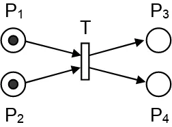
The basic Petri net is a directed graph consisting of places and transitions interconnected by directed arcs. In terms of modeling, transitions represent possible actions (or events); input places and output places represent pre-conditions and post-conditions for the action, respectively. The basic opera-tional rule concerns transition enabling and firing. A transition is enabled if every input place holds at least one token (i.e., all pre-conditions are true). An enabled transition may or may not fire after some time. When a transition fires, tokens move from the input places to the output places (i.e., the post-conditions become true). A simple example of an enabled transition T
with two input places and two output places is shown in Fig. 1. If it fires, the tokens at the input places (P1andP2) will be
removed and tokens will appear at the output places (P3 and
P4). Generally, there could be any number of input or output
places. Optionally, arcs can be assigned weights which are the number of tokens consumed or created when the related transition fires, but here all arc weights will be assumed to be one (and not shown explicitly) [24].
P
1P
2P
3P
4 [image:5.612.374.500.632.725.2]T
A Petri netN is defined by N= (P, T, I, O)whereP is a set of places,T is a set of transitions, I is the input function defining the input places for each transition, and O is the output function defining the output places for each transition. For attack modeling, places represent different security states, and transitions represent the actions of attackers. Concurrent attackers acting within the same system (and hence same Petri net) are straightforward to represent by multiple tokens. If the attackers are different from each other, colored tokens can account for them.
The general method to construct a Petri net model for coordinated cyber-physical attacks consists of these steps:
1) enumerate all possible security states of physical and cyber entities;
2) identify all possible cyber or physical attack actions affecting changes in security states.
The input places for a transition are the prerequisite conditions for that attack action, for example, physical tampering of a smart meter requires that a smart meter is first located and acquired. The output places for a transition are the outcomes of the action. The modeling process is straightforward but requires the security analyst to have extensive expertise in both physical and cyber security domains. In effect, the modeling approach does not make any distinction between the physical and cyber infrastructures nor distinctions between physical and cyber attacks.
B. Blackout Example
Petri net modeling is illustrated with an example based on a sequence of events during an historic blackout in midwestern and northeastern U.S. and Ontario, Canada on August 14, 2003. It began around 4:00 eastern daylight time and lasted four days. The result was due to an unintentional combi-nation of several electronic and physical circumstances, not a malicious attack, but the unfortunate series of events can be modeled for the purpose of illustration here as an attack producing the same results. The historic incident serves as an interesting example because of the intertwining of both cyber (computer) and physical (power grid) causes.
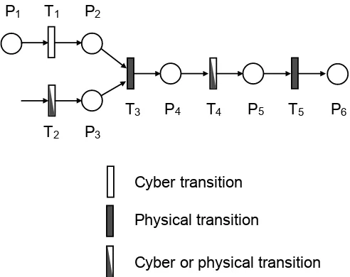
Fig. 2 shows a Petri net model following the main events in the timeline from a post-incident investigation [36]. For the sake of explanation, physical transitions are shown as filled bars, cyber transitions are empty bars, and half-filled bars may be physical or cyber. The purpose is to highlight how physical and cyber events were occurring concurrently but the nature of the transitions is not important to the Petri net structure.
Initially, the load in Northern Ohio was moderately high, and two of the region’s power production anchors were already shut down (P1). FirstEnergy’s Eastlake 5 generation unit
tripped (T1) leading to its shut down (P2). As the unit’s
reactive power output was increasing, the unit’s protection system detected that the output exceeded the unit’s capability and automatically tripped the unit off-line. In this model, transition T1 might be imagined as a cyber attack on the
unit’s control system causing it to shut down. Concurrently, the alarm and the logging system in FirstEnergy’s control room failed (T2) resulting in a situation where system operators were
P
2T
1P
3P
4P
5T
2T
3T
4P
1P
6Cyber transition
T
5Physical transition
[image:6.612.314.560.53.248.2]Cyber or physical transition
Fig. 2. Petri net model for hypothetical attacks in blackout example
unaware that the electrical system condition was starting to degrade (P3). Furthermore, the system operators were unaware
that the alarm system was impaired. Imagined as an attack, transition T2 could represent a stealthy electronic or physical
disabling of the alarm system (which is the reason it is shown as a half-filled bar).
Next, some of FirstEnergy’s 345-kV transmission lines began tripping out (T3) due to contact with overgrown trees
causing short circuits to ground. In the actual incident, the tree contacts were an unintentional combination of environmental causes, but a physical attack could conceivably have caused similar short circuits. The loss of these lines resulted in a state of more load placed on remaining working lines (P4). Due to
the loss of alarms, system operators were not fully aware of the line trips and the extent of the growing overload situation. The loss of the 345-kV transmission lines had increased loading on the underlying 138-kV system serving Cleveland and Akron, pushing those lines into overload. The overload caused some 138-kV lines to begin tripping (T4), eventually
leading to a loss of sixteen key 138-kV lines (P5). The loss
of these lines in turn overloaded the Sammis-Star 345-kV line (T5) causing it to fail (P6). The loss of the Sammis-Star line
and other transmission lines in northern Ohio was the critical state that triggered a subsequent cascade of failures that spread far beyond Ohio.
Clearly, the model in Fig. 2 has left out many details but the purpose of the example is to show how a Petri net model can capture coordinated attacks in a cyber-physical system. The cyber and physical infrastructures are vast and complicated in reality, and a more practically useful Petri net would be much larger to encompass all of the system components.
V. HIERARCHICALMETHOD TOCONSTRUCTPETRINET
MODEL
creating an attack model will be challenged with two daunting requirements. First, the Petri net model will be enormous in size to reflect all possible combinations of attacker actions and their consequences. The required effort to create the Petri net in a single step will become impractical. Second, the security analyst (or team of analysts) must be deeply knowledgable about both cyber and physical threats. It might be feasible for a small system but again the size and complexity of the smart grid makes this knowledge difficult to collect and fuse together.
Our objective here is a more practical method to construct a large scale Petri net attack model appropriate for the smart grid. Instead of constructing an immense Petri net in one step, our method is based on the presumption that small detailed attack models can be created separately by different security domain experts. For example, one domain expert may be knowledgable about physical attacks on smart meters, while another has expertise on cyber attacks on substations. Domain experts have a detailed understanding of threats within their separate specialized but limited fields. The challenge is automating a process to combine the separate detailed Petri nets into an unified model. In our construction method, the process is facilitated by a model description language.
Our model construction method consists of these steps: 1) separate “low level” detailed Petri net models are created
by domain experts for attacks within their areas of expertise;
2) a “high level” Petri net is created for the system at a high level of abstraction that includes critically important (though not all) places but ignores details of transitions; 3) definitions of all places and transitions are created using
the model description language;
4) identical places in the high level and low level Petri nets are matched;
5) the high level Petri net is expanded with the places and transitions from the low level Petri nets, matching up identical places.
Although our method might be called hierarchical because it proceeds from high level and low level Petri nets, our method is entirely different from the familiar concept of “hierarchical Petri nets.” Hierarchical Petri nets consist of a high level Petri net hiding details of a transition (i.e., a “substitution transition”), where the details of the substitution transition can be found in another Petri net (a subpage). Hierarchical Petri nets are simply a way to present a large complicated Petri net for easier visual understanding. The correspondences between the high level Petri net and its subpages are already mapped; a hierarchical Petri net has already been constructed. In contrast, we are proposing a construction method. Our method aims to construct a unified Petri net when the correspondences between a high level Petri net and low level Petri nets are not yet established. The correspondences must be found by matching identical places in the separate Petri nets, which is enabled by unique logical definitions.
The difficult step in our construction method is how to recognize that a place P in the high level Petri net is the same as a place P in a low level Petri net. Places must be defined uniquely such that the same place appearing in
different Petri nets can be discovered. Clearly, there can be many possible choices for a model description language. We suggest an approach similar to the formalism by Braynov and Jadliwala although they did not frame their work in the context of Petri nets [34].
The basic idea is that places can be defined as logical statements of “atomic formulae.” An atomic formula consists of a variable and its value. Variables represent all security-related entities in the system and can have predefined possible values. For example, a variable related to a smart meter could beouter casingwith possible values “intact” or “broken.” An atomic formula would be a combination of variable and value that is true for a Petri net place, for example, “outer casing = intact.” Another variable for a smart meter might be theoptical port with possible values “protected” or “compromised.” A place is defined by a logical “and/or” statement consisting of true atomic formulae with the general form:
(variable1 = value1)∧(variable2 = value2)∧. . .. For example, a place definition related to a smart meter might be:
(outer casing = intact) ∧(optical port = compromised). This statement defines a specific security state for the smart meter.
A complete set of variables and their possible values needs to be created for the smart grid. At present, it is an open research issue. Given semantics, each place will be defined uniquely by a logical statement, even when the same place occurs in different Petri nets.
The definition of transitions is a little more complicated than places but still straightforward. A transition is defined by a triplet (action, pre-conditions, post-conditions). The action is a name describing the attack action. Pre-conditions are the set of input places that must hold a token in order to enable the transition. Post-conditions are the set of output places for the transition. The general form for a transition is:
Transition:< action−name >
:preconditions< list−of−places >
:postconditions< list−of−places >
A. Smart Meter Example
Fig. 3 is an example to illustrate the construction method. For the sake of explanation, physical actions are shown as filled bars while cyber actions are shown as empty bars but the distinction is irrelevant to the Petri net. The example is not necessarily “typical” but chosen because it includes both physical and cyber attack actions intermingled in a single Petri net model. It could be easy to see that different domain experts may know separate parts of the model in Fig. 3, which motivates our construction method.
The model shows sequential actions towards ultimately obtaining cryptographic keys stored in the firmware of a smart meter (P6). Attackers may buy (T1) or steal (T2) a smart meter
to realize the acquisition of a meter (P1). With a meter in hand,
the physical casing may be broken (T4) to expose the internal
firmware may be dumped (T6) to read the firmware (P5). If the
firmware is encrypted, it may be cracked (T8) to obtain the
stored cryptographic keys (P6). Alternatively, attackers may
search for an operational smart meter (T3) and identify a target
(P2). Meters typically include an IEC 62056-21 optical port
for field configuration and testing. Bypassing possible physical protection (T5), attackers may gain access to the optical port
(P4). Typically the port requires password authentication. If
attackers can acquire or crack the password (T7), they may be
able to access the firmware (P5).
P1
P2
T1
P3
P4
P5 P6
T2
T3 T5
T4
T6
T7
T8
Cyber transition
Physical transition
[image:8.612.353.525.53.189.2]Cyber or physical transition
Fig. 3. Petri net example of cyber-physical attack on smart meter
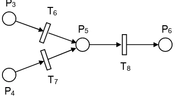
In this example, it is easy to imagine that different domain experts will be familiar with either cyber or physical attacks, and no individual expert may know all detailed threats in both cyber and physical domains. Hence, the domain experts are assumed to create separate low level detailed Petri net models for cyber and physical attacks. Fig. 4 is an example of a low level Petri net created by the cyber attack expert, and Fig. 5 are low level Petri nets created by the physical attack expert.
P3
P4
P5 P6
T6
T7
T8
Fig. 4. Low level Petri net models for cyber attacks
The method aims to unite the separate low level models by starting from a high level model that ignores some places and details in transitions. The security analyst is assumed to have a general knowledge about possible attacker actions that can affect critical security states, but does not have detailed knowledge about how the attacker actions. The security analyst creates a high level Petri net model shown in Fig. 6. At this level of abstraction, the model recognizes that an attacker may acquire a smart meter (P1) or target an operational smart
meter (P2), both conditions possibly leading somehow towards
P1
P2
T1
P3
P4
T2
T3 T5
[image:8.612.53.300.190.352.2]T4
Fig. 5. Low level Petri net model for physical attacks
access to the firmware (P5). The transitions in this model
represent a relationship between the places without specifying exact actions.
P
1P
2P
5Fig. 6. High level Petri net model
The next step defines all places as logical statements of formulae consisting of variables and their values. A (not exhaustive) example set of variables related to smart meter security might be as listed in Table I. In terms of these variables, every place in all Petri nets would have a unique definition consisting of a logical statement of variables and their values. For example, place P1 represents a condition
where an attacker has simply obtained a non-working, intact smart meter so the definition would be:
(operation = disconnected) ∧(physical casing = intact)∧
(power = off).
After defining all places, the important step in the method is expansion of the high level model with details incorporated from the low level models. The step begins by identifying that placesP1andP2in the high level Petri net can be found in the
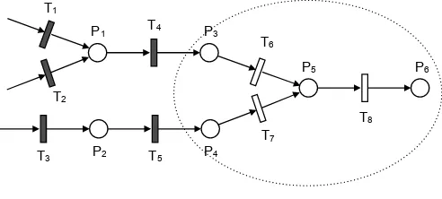
low level Petri nets in Fig. 5. The identification is possible by comparing and matching the place definitions. Having found matching places in the two Petri nets, the detailed Petri nets are drawn into the high level Petri net to create the intermediate result shown in Fig. 7, where the new details are highlighted in the dashed areas.
Similarly, place P5 can be identified in the low level Petri
net in Fig. 4. The high level Petri net can then be expanded further by adding details from the low level Petri net. When this is done, it may be noticed that places P3 and P4 in the
[image:8.612.378.496.282.388.2] [image:8.612.87.263.498.595.2]TABLE I
EXAMPLE VARIABLES FOR A SMART METER
Variables Possible values
Operation Operational; disconnected Physical casing Intact; broken
Tamper seals Intact; broken Optical IEC port Protected; accessible
Power On; off
Battery Present; removed Internal clock Working; errored; failed
Security logs Normal; altered; cleared Flash memory Protected; accessible
EEPROM Protected; accessible Firmware Protected; accessible Stored meter readings Protected; accessible Cryptographic keys Protected; broken
P5
P1
T1
P3
T2
T4
P2 P4
T3 T5
Fig. 7. High level Petri net model expanded with details
intermediate model of Fig. 7, leading to the composite result in Fig. 8. In this example, this happens to be the final result because all details from the low level Petri nets have been incorporated at this point.
P1
T1
P3
T2
T4
P2 P4
T3 T5
P5 P6
T6
T7
[image:9.612.53.299.512.623.2]T8
Fig. 8. High level Petri net model
VI. METHODVALIDATION
A “proof-of-concept” Python program was written to demonstrate the efficacy of the Petri net model construction method using the smart meter example in Sec. V-A. The program takes two inputs: a high level and a low level Petri net, and creates a new Petri net by merging the details from the low level Petri net into the high level Petri net. In our
experiments, the program was started with the high level Petri net in Fig. 6, and run successively with the low level Petri nets from Figs. 4-5, to create the final Petri net in Fig. 8.
In the program, a specific Petri net model is represented by a set of arrays: an array P for a set of places, and an array
N for a set of transitions. Each place is defined as a logical statement, as explained earlier, such as:
(variable1 = value1)∧(variable2 = value2)∧. . .. The program uses the 13 variables in Table 1, and within the program, a logical statement defining each place is represented by an array of 13 values of the form < value1, value2, . . . >. Each transition in N is defined by a pair < P reCond,P ostCond > whereP reCondis an array of input places andP ostCondis an array of output places for the transition.
Given a high level and low level Petri net as inputs, the program first checks if any state definition in the low level Petri net matches a state definition in the high level Petri net. If a match is found, the program determines which transitions in the high level Petri net will be affected by the details in the low level Petri net. That is, it determines the proper location in the high level Petri net to insert the details from the low level Petri net. Next, the program adds state definitions from the low level Petri net that are not present in the high level Petri net. In the last step, new transitions from the low level Petri net are added at the proper place in the high level Petri net.
Generally, the program carries out straightforward functions. The most complicated step is the final one where the new transitions from the low level Petri net are added into the high level Petri net. Some care needs to be taken to check for whether transitions from the low level Petri net are duplicated in the high level Petri net.
The proof-of-concept program was adequate for the small smart meter example described here but is not sophisticated enough for complex Petri nets. We have also not considered possible situations where human errors in the low level or high level Petri nets might create inconsistencies that could prevent our method from working correctly. More work is needed to improve the program and test it for more complex models, although the initial experiments with the smart meter example indicate that the method is feasible.
VII. CONCLUSIONS
For smart grid threats, we have argued that Petri nets are an appealing modeling tool because they offer more flexibility and expressiveness than traditional attack trees. An example in this paper shows that Petri nets can be useful for modeling cyber-physical attacks.The drawbacks of Petri nets are the expertise and human effort required for large models. For an enormous cyber-physical system like the smart grid, the usual modeling approach would be infeasible.
separate Petri nets. The important step of the construction method unifies the separate Petri nets by making use of a model description language. With unique place definitions, correspondences between identical places in separate Petri nets can be identified and matched. By this process, the details from low level Petri nets can be transferred and unified into a high level Petri net, as demonstrated by an example.
The aim of the paper is not an exact model for smart grid threats, which is impossible at this time due to lack of experience with real attacks in the smart grid. Instead, our goal is better modeling tools capable of accounting for sophisticated attacks on the smart grid which can be useful later when more knowledge about real attacks is obtained.
REFERENCES
[1] S. Amin and B. Wollenberg, “Toward a smart grid,”IEEE Power and Energy Mag., vol. 3, pp. 34–41, May 2005.
[2] (2003, Jul.) Grid 2030: a national vision for electricity’s second 100 years. U.S. Dept. of Energy. [Online]. Available: http://www. climatevision.gov/sectors/electricpower/pdfs/electric vision.pdf [3] (2009, Jul.) Smart grid system report. U.S. Dept. of Energy. [Online].
Available: http://www.oe.energy.gov/SGSRMain 090707 lowres.pdf [4] J. Fan and S. Borlase, “The evolution of distribution,”IEEE Power and
Energy Mag., vol. 7, pp. 63–68, Feb. 2009.
[5] H. Farhangi, “The path of the smart grid,” IEEE Power and Energy Mag., vol. 8, pp. 18–28, Jan. 2010.
[6] T. Garrity, “Getting smart,”IEEE Power and Energy Mag., vol. 6, pp. 38–45, Feb. 2008.
[7] A. Ipakchi and F. Albuyeh, “Grid of the future,”IEEE Power and Energy Mag., vol. 7, pp. 52–62, Feb. 2009.
[8] Office of the National Coordinator for Smart Grid Interoperability, “Nist framework and roadmap for smart grid interoperability standards release 1.0,” NIST, MD, Tech. Rep. special publication 1108, Jan. 2010. [9] T. Flick and J. Morehouse,Securing the Smart Grid. Burlington, MA:
Syngress, 2011.
[10] F. Cleveland, “Cyber security issues for Advanced Metering Infrastruc-ture (AMI),” in2008 IEEE Power and Energy Society General Meeting - Conversion and Delivery of Electrical Energy in the 21st Century, Pittsburgh, PA, Apr. 2008, pp. 1–5.
[11] F. Cohen, “The smarter grid,”IEEE Security and Privacy, vol. 8, pp. 60–63, Jan. 2010.
[12] H. Khurana, M. Hadley, L. Ning, and D. Frincke, “Smart-grid security issues,”IEEE Security and Privacy, vol. 8, pp. 81–85, Jan. 2010. [13] P. McDaniel and S. McLaughlin, “Security and privacy challenges in the
smart grid,”IEEE Security and Privacy, vol. 7, pp. 75–77, Mar. 2009. [14] Smart Grid Interoperability Panel – Cyber Security Working Group,
“Smart grid cyber security strategy and requirements,” NIST, MD, Tech. Rep. draft NISTIR 7628, Feb. 2010.
[15] T. Chen, “Survey of cyber security issues in smart grids,” in Cyber Security, Situation Management, and Impact Assessment II; and Visual Analytics for Homeland Defense and Security II (part of SPIE DSS 2010), Orlando, FL, Apr. 2010, p. 77090D.
[16] W. Kroger, “Critical infrastructures at risk: a need for a new conceptual approach and extended analytical tools,”Reliability Engineering and System Safety, vol. 93, pp. 1782–1787, Jan. 2008.
[17] S. Mauw and M. Oostdijk, “Foundations of attack trees,” in 8th An-nual International Conference on Information Security and Cryptology (ICISC 2005), Seoul, Korea, Dec. 2005, pp. 186–198.
[18] K. Ingols, M. Chu, R. Lippmann, S. Webster, and S. Boyer, “Modeling modern network attacks and countermeasures using attack graphs,” in
2009 Annual Computer Sec. Applic. Conf. (ACSAC), Austin, TX, Dec. 2009, pp. 117–126.
[19] P. Khand, “System level security modeling using attack trees,” in2nd Int. Conf. on Computer, Control and Commun. (ICA 2009), Karachi, Pakistan, Feb. 2009, pp. 1–6.
[20] K. Schneider, C.-C. Liu, and J.-P. Paul, “Assessment of interactions between power and telecommunications infrastructures,”IEEE Trans. Power Sys., vol. 21, pp. 1123–1130, Aug. 2006.
[21] C.-W. Ten, C.-C. Liu, and M. Govindarasu, “Vulnerability assessment of cybersecurity for scada systems using attack trees,” inIEEE Power Engineering Society General Meeting, Tampa, FL, Jun. 2007, pp. 1–6.
[22] S. McLaughlin, D. Podkuiko, and P. McDaniel, “Energy theft in the advanced metering infrastructure,” in 4th Int. Workshop on Critical Information Infrastructures Security (CRITIS 2009), Bonn, Germany, Sep. 2009, pp. 176–187.
[23] J. Peterson, “Petri nets,”ACM Computing Surveys, vol. 9, pp. 223–252, Sep. 1977.
[24] T. Murata, “Petri nets: properties, analysis and applications,”Proc. IEEE, vol. 77, pp. 541–580, Apr. 1989.
[25] M. Diaz,Petri Nets: Fundamental Models, Verification and Applications. NY: Wiley, 2009.
[26] V. Kordic,Petri Net Theory and Applications. Vienna: I-Tech Education and Publishing, 2008.
[27] R. David and H. Alla, Discrete, Continuous, and Hybrid Petri Nets. Berlin: Springer-Verlag, 2005.
[28] J. McDermott, “Attack net penetration testing,” in2000 Workshop on New Security Paradigms (NSPW’00), Cork, Ireland, Sep. 2000, pp. 15– 21.
[29] G. Dalton, R. Mills, J. Colombi, and R. Raines, “Analyzing attack trees using generalized stochastic petri nets,” in2006 IEEE Workshop on Info. Assurance, West Point, NY, Jun. 2006, pp. 116–123.
[30] R. Wu, W. Li, and H. Huang, “An attack modeling based on hierarchical colored petri nets,” in IEEE Int. Conf. on Comp. and Elec. Engin. (ICCEE 2008), Phuket, Thailand, Dec. 2008, pp. 918–921.
[31] O. Dahl and S. Wolthusen, “Modeling and execution of complex attack scenarios using interval timed colored petri nets,” inIEEE Int. Workshop on Innovative Arch. for Future Gen. High-Perf. Proc. and Sys., Kona, Hawaii, Jan. 2006, pp. 49–55.
[32] O. Gursesli and A. Desrochers, “Modeling infrastructure interdepen-dencies using petri nets,” in2003 IEEE Int. Conf. on Systems, Man and Cybernetics (SMC’03), Wash. DC, Oct. 2007, pp. 1506–1512. [33] J.-C. Laprie, K. Kanoun, and M. Kaaniche, “Modelling
interdependen-cies between the electricity and information infrastructures,” in26th Int. Conf. on Computer Safety, Reliability and Security (SAFECOMP 2007), Nuremberg, Germany, Sep. 2007, pp. 54–67.
[34] S. Braynov and M. Jadliwala, “Representation and analysis of coor-dinated attacks,” in 2003 ACM Workshop on Formal Methods in Sec. Engin. (FMSE’03), Wash. DC, Oct. 2003, pp. 43–51.
[35] U. C. O. of Technology Assessment,Physical Vulnerability of Electric Systems to Natural Disasters and Sabotage, OTA-E-453. Wash. DC: U.S. Government Printing Office, 1990.
[36] U.-C. P. S. O. T. Force, “Final report on the august 14, 2003 blackout in the united states and canada: Causes and recommendations,” U.S.-Canada Power System Outage Task Force, Tech. Rep., Apr. 2004. [37] (2008, Feb.) Advanced metering infrastructure. National Energy
Technology Laboratory. [Online]. Available: http://www.netl.doe. gov/smartgrid/referenceshelf/whitepapers/AMI%20White%20paper% 20final%20021108%20%282%29%20APPROVED 2008 02 12.pdf [38] (2009, Jun.) A vision for the smart grid. National
Energy Technology Laboratory. [Online]. Available: http: //www.netl.doe.gov/smartgrid/referenceshelf/whitepapers/Whitepaper The%20Modern%20Grid%20Vision APPROVED 2009 06 18.pdf [39] C.-W. Ten, C.-C. Liu, and M. Govindarasu, “Vulnerability assessment
of cybersecurity for scada systems,”IEEE Trans. Power Sys., vol. 23, pp. 1836–1846, Nov. 2008.
[40] A. Creery and E. Byres, “Industrial cybersecurity for a power system and scada networks - be secure,”IEEE Industry Applications Mag., vol. 13, pp. 1836–1846, Jul. 2007.
[41] Z. Lukszo, G. Deconinck, and M. Weijnen,Securing Electricity Supply in the Cyber Age. Dordrecht: Springer, 2009.
[42] (2008, Dec.) AMI system security requirements v1.01. AMI Security Acceleration Project AMI-SEC Task Force (AMI-SEC-ASAP). [Online]. Available: http://www.oe.energy.gov/DocumentsandMedia/ 14-AMI System Security Requirements.pdf
[43] (2009, Dec.) Security profile for advanced metering infrastructure. Advanced Security Acceleration Project (ASAP-SG). Knoxville, TN. [Online]. Available: http://osgug.ucaiug.org/utilisec/amisec/Shared% 20Documents/AMI%20Security%20Profile%20(ASAP-SG)/AMI% 20Security%20Profile%20-%20v1 0.pdf
[44] A. Hamlyn et al., “Computer network security management and au-thentication of smart grids operations,” in2008 IEEE Power and Energy Society General Meeting - Conversion and Delivery of Electrical Energy in the 21st Century, Pittsburgh, PA, Jul. 2008, pp. 1–7.
[45] A. Metke and R. Ekl, “Smart grid security technology,” in 2010 Innovative Smart Grid Technologies (ISGT), Gaithersburg, MD, Jan. 2010, pp. 1–7.
Thomas M. Chenis currently a professor in net-works in the College of Engineering at Swansea University, Wales, UK. He was previously an asso-ciate professor in the Department of Electrical Engi-neering at Southern Methodist University in Dallas, Texas. Prior to SMU, he worked on high-speed networking research at GTE Laboratories (now Ver-izon) in Waltham, Massachusetts. He received the BS and MS degrees in electrical engineering from the Massachusetts Institute of Technology, and PhD in electrical engineering from the University of Cal-ifornia, Berkeley. He currently serves as editor-in-chief of IEEE Network magazine, technical editor for IEEE Communications Magazine, editor for IEEE Communications Surveys, associate editor for Journal on Security and Communication Networks, and associate editor for International Journal of Digital Crime and Forensics. He is the co-author ofATM Switching(Artech House) and co-editor of Broadband Mobile Multimedia: Techniques and Applications (CRC Press). He received the IEEE Communications Societys Fred Ellersick best paper award in 1996.
Juan Carlos Sanchez-Aarnoutsereceived the Au-tomation and Electronic Engineering degree in 2001 from the Polytechnic University of Cartagena (UPCT), Spain. In May 2006, he received the Ph.D. degree in Telecommunication from the UPCT, Spain. He has been an assistant professor at the Department of Information Technologies and Communications at the Polytechnic University of Cartagena since 2002. He has been involved in several national research projects related to switching and multicast technologies. He is author of several papers, book chapters and conference papers in the fields of multicast protocols and P2P. His actual research interests include Smart Grid, Power Line Communications and P2P.