A study of vortex ring generation by a circular disc with its
application in bionic investigation
Ruo-xin Li
*, Lai-bing Jia and Qing Xiao
Department of Naval Architecture, Ocean and Marine Engineering, University of Strathclyde, Glasgow, G4 0LZ, UK
Abstract: Numerical simulation on a vortex ring generated by an impulsive started disc is studied. Commercial CFD software is used for the numerical simulation. Modelling results are compared with previous experimental data. The circulation, vortex core position and symmetric breaking time are discussed at two different velocities. Results show that a larger velocity leads to a greater vortex ring circulation, a shorter developing time for occurring asymmetry phase comparing with a smaller velocity.
Keywords: disc impulsive start; vortex ring; circulation; vortex core
Article ID: 1671-9433(2010)01-0000-00
1 Introduction
1Experiencing natural selection for thousands of years, the aquatic creatures have evaluated fully developed survival systems. This enables them having various merits, such as a fast propulsion, a stable maneuvering, and a rapid escaping. Referring to the propulsion aspect, different aquatic creatures employ various methods. Generally, there are two type propulsion mechanisms, i.e. a jet and oscillating propulsion in the wake of aquatic animals. Most fish and aquatic mammals employ oscillation propulsion mechanism while some mollusks, such as squid and jellyfish, are based on jet propulsion mechanism. For example, a squid generates jet vortex rings in its body wake. Due to the complication of vortex generation by real living creatures, a fundamental study on axial symmetric vortex rings either by experiment or by modeling is investigated for a decade. Basically, there are two methods associated with the axisymmetric vortex generation, i.e. fluid discharges from an orifice or a nozzle and a sudden started circular disc.
Gharib, Rambod & Sharriff (1997) studied the jet vortex ring generated through impulsively piston setup. They found that ratio of piston stroke to diameter (L/D) affected the vortex rings generation. With a large stroke ratio, trailing jet was after the leading vortex ring. At small stroke ratio, only one vortex ring was observed. One important concept, ‘formation number’ was first defined based on the transition between above two forms. Linder and Turner (2001) noticed that for a given energy input, the vortex ring ejected through a pipe existed the maximum impulse, circulation and volume, defined as ‘optimal vortex’. In application, this ‘optimal vortex’ can be utilized on the study of fish optimal thrust production as these two phenomena have almost the same
Received date:
Foundation item: Supported by
*Corresponding author Email: [email protected]
mechanisms. Furthermore, Linder and Turner (2004) pointed out that although different aquatic creatures employ various propulsion methods, they face different survival conditions. Thus, the propulsion efficiency cannot be considered as the unique principle to distinguish the merits between jet and oscillating mechanisms. One example is given for squid. Its jet propulsion efficiency is lower than other aquatic animals which use the same propulsion mechanism. However, this cannot be simply explained as its low efficiency because when facing predators, rapid acceleration and escaping has huge importance than the so-called ‘efficiency’ during sustainable swimming. Dabiri (2009) verified that there is a unifying principle for the optimal vortex formation on propulsion of bio-relevant systems. With the definition of ‘formation number’, the Strouhal Frequency Constraints is found to exist for animal’s oscillation and flapping.
On the study of vortex rings generated by disc or cylinder, Taylor (1953) gave a study on a circular disk suddenly disappeared after impulsive started in the perfect fluid. Circulation, translational velocity, and the radius ratio of vortex ring and disk were given as
1
2 2
2 0
4 4
1
c
r
Ur r Uc
rdr
c c
2
2
2 3
R
c
' 2
8 1
log 4
Uc R
V
R a
,
2
8 7 1
log
4 6
R c
a R
.
Velocity and drag coefficient comparisons were examined under various Reynolds numbers within the early stage of the flow development. Johari and Stein (2002) investigated a three-dimensional vortex ring growth behind a zero thickness disk in viscous flow. Their results on the circulation time collapsed matches the formation number given by Gharib et al. (1997). Shenoy and Kleinstreuer (2008) conducted a vortex shedding study with flow passing through a thin circular disk under different Reynolds numbers conditions. Four regimes were observed before the vortex rings were fully developed, but the prime formation was not studied.
Different from previous studies, Yang et al. (2012) studied on the early formation process of the vortex ring generated by an impulsively started thin circular disc experimentally. The study revealed different mechanisms of vortex generation could lead to a similar formation process. A universal principle of optimal vortex formation is found. Their study also found three developing phases during which the disc vortex ring forms, i.e. rapid growth phase, steady growth phase and non-axisymmetric phase. Due to the limitation of experimental method, some detailed information on the vortex ring generation was not measured.
Present work is mainly based on a numerical simulation of the vortex ring generation by an impulsive started disc. The simulation parameters are the same as previously experimentally studied by Yang et al. (2012). A commercial Computational Fluid Dynamics solver is employed to carry out the simulation. Circulation and vortex core coordinate comparisons are given in details. At the start time for the asymmetry phase is discussed.
2 Numerical simulations
The original problem described by Yang et at. (2012) is a disc accelerates from stationary to a constant velocity v in an acceleration time t. During this period, rapid growth, steady growth and breaking phase occurs. This work supposes the acceleration finishes instantaneously. In order to avoid the error induced by dynamic mesh, coordinate conversion is used in the simulation. The incoming flow has a relative velocity at the beginning of the simulation. This replaces the motion of the disc. As coordinate conversion will generate a force at the acceleration phase, the force can be omitted as we mainly considers the phenomena after the acceleration completed.
The simulation is carried out by the commercial software ANSYS Fluent 14.5. Its solver is based on finite volume method. Basic theory used in Fluent is by discretising transport equation
V A A V
dV d d S dV
t
V A
A
.A first order implicit time marching scheme is used for time transient. Second-order upwind scheme is employed for
diffusion term discretization. Pressure-velocity coupling can be achieved by the SIMPLE scheme.
Before we start a systematic study, a computational boundary domain topology testing is performed. Two shapes are tested, i.e. rectangular and cylinder domain as shown in Fig. 1 with an inlet velocity v=5.28sm/s, which is the smallest velocity in Yang et al. (2012) experiments. A comparison for iso-surface vorticity contour at Tn =4 is shown in Fig. 1 for rectangular and cylinder domain. A visible deformation of vortex ring appears with a rectangular domain, which may cause further errors in simulation results. Therefore, a cylindrical domain is used in the following simulation.
Rectangular zone Cylinder zone
Geometry
Iso-surface of vorticity magnitude at Tn=4
Fig. 1 Different topology for computational domain
The model studied here is fluid passing by a 30mm diameter and 2mm thickness disc in a cylindrical domain. The overall dimensional of domain is 300mm in diameter and 360mm in length as shown in Fig. 2. This domain has two sub-zones: core zone and peripheral zone. Mesh is clustered near the disc to well capture the boundary layer. Inertial force and
viscous force are estimated as 2
i
F L U and
2
v
U
F L
. The thickness of boundary layer is
calculated as L
U
, supposing the kinematic viscosity
of water being as 1E-6m s2/ . The core zone is high
3
Fig. 2 Computational domain
3 Methodology
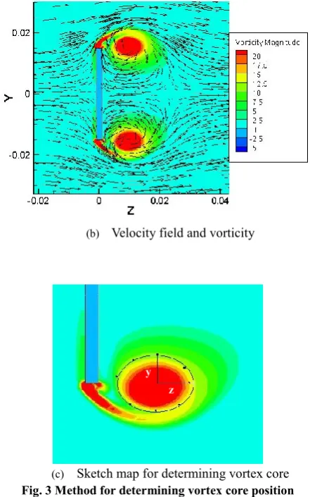
According to Yang et al. (2012), the evolution of the disc vortex ring is that the vortex grows with the growth of its circulation during the initial vortex development phases. When the circulation reaches a maximum value, vortex ring stops its growing. After this stage, an asymmetric phase takes place. Vortex core position is one important parameter to describe this problem. The method used to determine the shape and centre of the vortex is based on the Rankine vortex theory. Fig. 3(a) shows the relation between core distance and velocity distribution of the original Rankine vortex. A near linear distribution velocity within core radius of r0 and an external flow velocity inversely proportional to
radius can be obtained. Fig. 3 (b) shows the velocity distribution on Y-Z planar during axial-symmetric stage. Two zones can be observed. The velocity inner side of the core zone can be considered as linear distribution approximately. External flow rate is inversely proportional to the radius. Thus, our vortex data processing can be based on Rankine vortex, which has similar properties. Fig. 3(c) shows the sketch of vortex core. By locating the maximum and minimum velocity on a vortex line through vortex core, the vortex core size can be defined as the distance between the maximum and minimum velocity. Several directions extreme values are found to define y and z shown in Fig. 3(c). The edge of the vortex core can be ensured. The shape of vortex core can be considered as oval. The boundary of the vortex core is ensured to calculate out circulation and the position of vortex core.
(a) Original Rankine vortex
(b) Velocity field and vorticity
[image:3.595.311.532.73.426.2](c) Sketch map for determining vortex core
Fig. 3 Method for determining vortex core position
4 Results
4.1 Circulation
Fig. 4 shows the evolution of circulation over time under two different velocities. The formula used to calculate
circulation is i
i
ds dxdr
, where i is thevorticity magnitude in each calculation cell, and dxdr is integration area. Dimensionless circulation is defined as
n c
, where c 2
UD
, U and D is flow inlet velocity
and disc diameter respectively. In Fig. 4, it can be seen that the dimensionless circulation has a common trend with the time increases, similar to Yang et al. (2012)’s results. That is, a vortex core experience an initial rapid increasing circulation phase, followed by a steady increasing period before the asymmetric phenomena occurs. One observation is that a large incoming flow velocity leads to a short rapid increasing phase and a large circulation magnitude.
[image:3.595.62.274.84.241.2]Fig. 4 Dimensionless circulation comparison
4.2 Vortex core position
As we consider the vortex ring as a Rankine vortex, the edge of vortex core can be determined by identifying the point at which the velocity achieves its maximum/minimum value. The shape of vortex core is considered as an oval. To make sure the position of a vortex core, a computational area should be selected. The position can be calculated as
i i i core
i i
X X
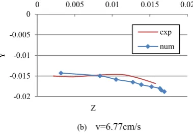
, i stands for the vorticity magnitude ineach computational zone. Fig. 5 shows the half part of the vortex core coordinate movement with time in x=0 plane. The disc centre is fixed at (0, 0) point. Two velocities results are given and compared with Yang et al. (2012)’s experimental results. With the time increases, the vortex core begins to move away from the disc and expands transversely. This time period is the fast increasing phase. After that, the vortex begins to grow vertically, indicated by the core coordinate starts moving away from the central axis of symmetry plan. A large flow velocity can lead to a longer horizontal distance.
(a) v=5.28cm/s
[image:4.595.321.511.83.214.2](b) v=6.77cm/s
Fig. 5 Vortex core position under different velocity
4.3 Symmetric breaking
[image:4.595.312.533.459.585.2]The time for the onset of axisymmetric phase is discussed here. In the axil-symmetric phase, vortex ring appears symmetrically in Y-Z and X-Y planar. Thus two vortex core sections have symmetric coordinates about the axis. The value of coordinate ratio equals to 1 approximately. When the vortex ring begins to show asymmetric behaviours, differences between the two core sections appear. The core coordinate differs from each other. Fig. 6 shows the ratio in Y and Z coordinates with dimensionless flow time in Y-Z planar. Clearly seen from figure is that, after some initial time stages, the ratio begins to differ from 1 significantly. The turning point of v=5.28cm/s is later than the one of v=6.77cm/s. This indicates that large velocity can ensure the vortex ring performing asymmetry more quickly. Thus, disc vortex ring can get saturation quicker and become asymmetry earlier with a high inlet flow velocity.
Fig. 6 Coordinate ratio presents for the symmetry breaking
5 Conclusions
This work presents a numerical simulation of the formation process of vortex ring formed by flow passing a thin disc. Comparisons of numerical simulated results with experimental results are carried out for vortex ring circulation, vortex core coordinate at two different flow velocities. Both experimental and modelling results show that a large velocity brings to a short symmetry phase with large circulation as compared to small incoming velocity. Rankine vortex method provides a new analytical means for 0
1 2 3 4 5 6
0 1 2 3 4 5 6
Γ
n
Tn
Exp. data at v=5.28cm/s Exp. data at v=6.77cm/s Num Sim at v=5.28cm/s Num Sim at v=6.77cm/s
-0.02 -0.015 -0.01 -0.005 0
0 0.005 0.01 0.015 0.02
Y
Z
num exp
-0.02 -0.015 -0.01 -0.005 0
0 0.005 0.01 0.015 0.02
Y
Z
exp
num
0.8 0.85 0.9 0.95 1 1.05 1.1
0 2 4 6 8 10 12
Ratio
Time (s) Yratio(5.28)
Yratio(6.77)
Zratio(5.28)
5
our future investigation on vortex ring problem.
Acknowledgement
The work is supported by the K.C. Wong Education Foundation and Royal Society. Results were obtained using the EPSRC funded ARCHIE-WeSt High Performance Computer (www.archie-west.ac.uk). EPSRC grant no. EP/K000586/1.
References
Dabiri, J. O. (2009). Optimal vortex formation as a unifying principle in biological propulsion. Annual Review of Fluid Mechanics, 41, 17-33.
Gharib, M., Rambod, E., & Shariff, K. (1998). A universal time scale for vortex ring formation. Journal of Fluid Mechanics, 360, 121-140.
Higuchi, H., Balligand, H., & Strickland, J. H. (1996). Numerical and experimental investigations of the flow over a disk undergoing unsteady motion.Journal of fluids and structures, 10(7), 705-719.
Johari, H., & Stein, K. (2002). Near wake of an impulsively started disk. Physics of Fluids (1994-present), 14(10), 3459-3474. Koumoutsakos, P., & Leonard, A. (1995). High-resolution
simulations of the flow around an impulsively started cylinder using vortex methods. Journal of Fluid Mechanics, 296, 1-38. Linden, P. F., & Turner, J. S. (2001). The formation of 'optimal'
vortex rings, and the efficiency of propulsion devices. Journal of Fluid Mechanics, 427, 61-72.
Linden, P. F., & Turner, J. S. (2004). ‘Optimal’vortex rings and aquatic propulsion mechanisms. Proceedings of the Royal Society of London. Series B: Biological Sciences, 271(1539), 647-653.
Shenoy, A. R., & Kleinstreuer, C. (2008). Flow over a thin circular disk at low to moderate Reynolds numbers. Journal of Fluid Mechanics, 605, 253-262.
Taylor, G. I. (1953). Formation of a vortex ring by giving an impulse to a circular disk and then dissolving it away. Journal of Applied Physics, 24(1), 104-104.