DESIGN AND DEVELOPMEMT OF UNDER-ACTUATED MYO-ELECTRIC PROSTHESIS HAND USING RAPID PROTOTYPING TECHNOLOGY
LOH KOK YONG
This Report Is Submitted In Partial Fulfillment of Requirements for the Bachelor Degree of Electronic Engineering (Computer Engineering)
Fakulti Kejuruteraan Elecktronik Dan Kejuruteraan Komputer Universiti Teknikal Malaysia Melaka
UNIVERSTI TEKNIKAL MALAYSIA MELAKA
FAKULTI KEJURUTERAAN ELEKTRONIK DAN KEJURUTERAAN KOMPUTER BORANG PENGESAHAN STATUS LAPORAN
PROJEK SARJANA MUDA II
Tajuk Projek : ………
………
Sesi Pengajian :
Saya ……….. (HURUF BESAR)
mengaku membenarkan Laporan Projek Sarjana Muda ini disimpan di Perpustakaan dengan syarat-syarat kegunaan seperti berikut:
1. Laporan adalah hakmilik Universiti Teknikal Malaysia Melaka.
2. Perpustakaan dibenarkan membuat salinan untuk tujuan pengajian sahaja.
3. Perpustakaan dibenarkan membuat salinan laporan ini sebagai bahan pertukaran antara institusi pengajian tinggi.
4. Sila tandakan ( √ ) :
SULIT* *(Mengandungi maklumat yang berdarjah keselamatan atau kepentingan Malaysia seperti yang termaktub di dalam AKTA RAHSIA RASMI 1972)
TERHAD** **(Mengandungi maklumat terhad yang telah ditentukan oleh organisasi/badan di mana penyelidikan dijalankan)
TIDAK TERHAD
Disahkan oleh:
__ ________________________ ___________________________________ (TANDATANGAN PENULIS) (COP DAN TANDATANGAN PENYELIA)
“I hereby declare that the work in this project is my own except for summaries and quotations which have been duly acknowledge.”
Signature : ...
Author : LOH KOK YONG
“I acknowledge that I have read this report and in my opinion this report is sufficient in term of scope and quality for the award of Bachelor of Electronic Engineering
(Computer Engineering) with Honours.”
Signature : ...
Supervisor’s Name : DR. SOO YEW GUAN
Thank you for my beloved family, my supervisor and all the lecturers who guided me, and to all my friends for giving me mentally and moral support during
ACKNOWLEGDEMENT
First of all, I would like to express my special thanks of gratitude to all those who helped me to complete my Final Year Project. Especially my parents and family for supporting me and provide me resources to complete this project.
Secondly, a special thank I give to my supervisor, Dr. Soo Yew Guan who has been provided material and component of this project to me. Besides, Dr. Soo gave me the fully support and clear guidance in term of knowledge and experience to help me finish the project in time.
Furthermore, I would like to acknowledge with much appreciation to my friends, Ali Mohammad and Liao Shing Wen. They shared the ideas and knowledge about EMG signal processing and motor driver design to guide me in completing the project. Both of them had given me a lot of encouragement and tips to improve my project.
ABSTRACT
ABSTRAK
Projek ini adalah menggambarkan tentang prototaip pantas tangan palsu telah
diubah suai daripada dua sendi kepada tiga sendi dengan tujuan untuk meningkatkan
fleksibiliti. Perisian yang digunakan untuk mengubah suai dan reka bentuk jari yang
buru adalah Solidwork. Tangan palsu yang modular, kos rendah dan ringan dalam
projek ini adalah dibina dan dicetak dengan menggunakan teknologi percetakan 3D.
Prototaip asal adalah beroperasi dengan menggunakan penderia tekanan daripada
kulit, manakala tangan palsu dalam projek ini adalah beroperasi dengan pelaksanaan
menangkap isyarat Electromyography daripada otot lengan untuk meningkatkan
kecekapan tangan palsu. Kaedah yang digunakan untuk memproseskan isyarat
Electromyography adalah root mean square teknik dan terdapat hanya dua gerak
isyarat telah dikelaskan dalam projek ini. Oleh itu, nilai ambang telah dikirakan dari
penjumlahan RMS tangan dibuka dan ditutup, kemudian dibahagikan dengan dua.
Kaedah ini mempunyai tindak balas yang cepat dan tepat pada pergerakan tangan
palsu. Tangan adalah sangat penting kepada kita, terutamanya dalam aktiviti harian,
oleh itu, projek ini adalah berpatutan untuk semua peringkat pengguna dan lebih
TABLE OF CONTENT
CHAPTER TITLE PAGE
PROJECT TITLE i
REPORT STATUS APPROVAL FORM ii
DECLARATION iii
SUPERVISOR APPROVAL iv
DEDICATION v
ACKNOWLEGDEMENT vi
ABSTRACT vii
ABSTRAK viii
TABLE OF CONTENT ix
LIST OF FIGURES xi
LIST OF TABLES xiii
I INTRODUCTION 1
1.1 Project Background 1
1.2 Objectives 2
1.3 Scope of Project 2
II LITERATURE REVIEW 4
2.1 Comparison between 3D Design Software 4
2.2 Signal Graph plotting Software 6
2.3 The Prosthesis Hand 6
2.4 Conclusion 15
III PROJECT METHODOLOGY 16
3.1 Project Flow 16
3.2 Project Methodology 18
3.3 Work flow 19
3.3.1 Mechanical Finger Design 19
3.3.2 Motor Driver Circuit Design 21
3.3.3 EMG Signal Processing 22
3.3.4 Arduino Program Flow 23
3.3.5 Control System 25
IV RESULT AND DISCUSSION 27
4.1 Result of Design Prosthetic Finger 27
4.1.1 Finger Design 27
4.1.2 Build the Prosthetic Hand by using 3D
Printing Technology 30
4.2 Result of Controlling Actuator 34
4.2.1 Motor Driver Circuit Design 35
4.2.1 Arduino code 36
4.3 Result of Electromyography (EMG) Signal
Processing Technique 37
4.3.1 Capture EMG Signal 37
4.3.2 Signal Processing 39
4.3.2 Plotting Graph 40
4.4 Control Movement of Finger by EMG Signal 43 4.4.1 Result on Testing Servo Motor Angle 43 4.4.2 Result Code of Open and Close All Fingers 43
4.5 Discussion 44
4.5.1 Modular Prosthetic and Hand Design 44 4.5.2 Low Cost Prosthetic Hand Design 45 4.5.2 Light Weight Prosthetic Hand Design 45 4.5.2 Under-actuated Myo-electric Prosthetic Hand 46
4.6 Conclusion 47
V CONCLUSION 48
5.1 Conclusion 48
5.2 Future Recommendation 48
REFERENCE
LIST OF FIGURES
NO TITLE PAGES
1.1 Force analyse to holding a round surface. 3
2.1 The Von Berlichingen, made of iron, 1500s. 4
2.2 Multi attachment of prosthetic hand. 5
2.3 CAD drawing of the first prototype grasping cylinder with
3-segment of thumb [3]. 6
2.4 Model of second prototype grasping a cylinder with 2-segment
of thumb [3]. 6
2.5 Image of multifunctional prosthesis hand [4]. 7 2.6 Mechanical hand design with one actuator [5]. 8
2.7 The control system create by MATLAB [6]. 10
2.8 The mechanical structure of fingers [7]. 11
2.9 Control system diagram [7]. 11
3.1 How myo-electric prosthetic hand work 16
3.2 The mechanical structure of finger design. 16
3.3 Flow chart of project methodology 18
3.4 The mechanical structure of finger design.. 19 3.5 The dimension structure of finger design part 1. 20 3.6 The dimension structure of finger design part 2. 20 3.7 The dimension structure of finger design part 3. 20
3.8 The block diagram of circuit design. 21
3.9 Flow chart of program code part 1. 23
3.10 The flow chart of program code part 2. 24
3.11 The basic flow chart diagram of control system. 25
3.12 Corresponding position for each finger. 28
4.1 The original finger of prosthetic hand. 28
4.3 The prototype dimension of fingertips. 29 4.4 The prototype dimension of upper middle phalanx. 29 4.5 The prototype dimension of lower middle phalanx. 29
4.6 The prototype of finger design. 30
4.7 The prototype of finger design and assembly the whole hand
design. 30
4.8 Using Cura software to display the G-code of plam and plam
cover. 31
4.9 Using Cura software to display the G-code of all finger parts.31 31
4.10 Beginning state of 3D printing. 32
4.11 Complete state of 3D printing. 32
4.12 PLA material for 3D printing. 33
4.13 PLA material for 3D printing. 34
4.14 The circuit board diagram of motor driver shield. 35
4.15 Completed of hardware connection. 36
4.16 Code of declaring servo motor variables. 37
4.17 Assign pins of servo motor variables. 37
4.18 Olimex EKG/EMG shield. 38
4.19 Code of EMG Shield configuration. 39
4.20 Code of rectifier the EMG raw signal. 40
4.21 Code of RMS value. 40
4.22 Processing Code of read serial COM port. 41
4.23 Processing Code of plotting EMG signal graph. 41
4.24 Graph of EMG raw signal. 42
4.25 Graph of EMG raw signal after rectifier. 42
LIST OF TABLE
NO TITLE PAGES
2.1 Invented user of 3D softwares. 4
2.2 Basic data of three 3d design software. 5
4.1 Result of corresponding angle for all fingers. 43
CHAPTER 1
INTRODUCTION
1.1 Project Background
The number of amputees are increasing yearly due to war, accidents, diseases and etc. Hand is the very important to us especially in daily activity, for example hand is used for grabbing objects, lifting, writing and a lot of things we do in life. However, with the loss of limb will cause a lot of troubles when carrying on daily activity. Thus, prosthesis hand is a tool to help limbs amputees to recover a part of self- confident and making them believed that there is still hope to regain back a partial life of a normal healthy individual. The prosthesis hand acts as a tool to replace the lost limbs physical appearance. As a matter of fact, it works as an aid to help in providing some of the functions that is lost due to accident, war or congenital condition. Moreover, the prosthesis hand is an interchangeable device that can be used only when needed. Much effort in the field of upper-extremity prosthesis research is directed towards the development of prostheses as limb replacements.
strong point bring out a costly prosthesis hand and unaffordable by most of the consumer.
Most of the amputees are not capable of purchasing a highly functional prosthesis hand even if those who managed to purchase it, they also fear of damaging the prosthesis because it is the maintenance fees are costly and they are forced to avoid using it for daily basic activity [2]. Therefore, a good prosthesis hand is a tool that can help in recovering the health and life of limb amputees with the prices that can be afforded by all amputees. Hence, a light weight, low cost with its outlook that is similar to human’s hand with five fingers is designed in this project.
1.2 Objectives
In this project, there are two objectives that needed to be achieved. The first objective of this project is, to design and build a modular, low-cost and light-weight prosthetic hand. The second objective is to ensure the 3D designed prosthetic hand can be operated by using electromyography signal.
1.3 Scope of Project
Figure 1.1: Force analyse to holding a round surface.
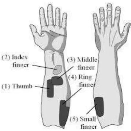
Olimex board is open source hardware electrocardiography electromyography shield and it can be suited for Arduino board. It can attach on top of the Arduino Uno microcontroller board. In order to capture raw Electromyography (EMG) signal from muscle, Olimex board is required to connect with three lead Differential Muscle /EMG sensors and Snap connector with gel ECG electrodes. The EMG sensor will attach to the forearm muscle of the user to detect signal captured from muscle when there is different movement performed by fingers. Arduino UNO board is used to read the analogue signal and process the signal with the use of root mean square equation.
CHAPTER 2
LITERATURE REVIEW
This chapter discusses about all the researches that have been done in the past which is related to the title of the project. All researches done is being compared and discussed critically.
2.1 Comparison between 3D Design Software
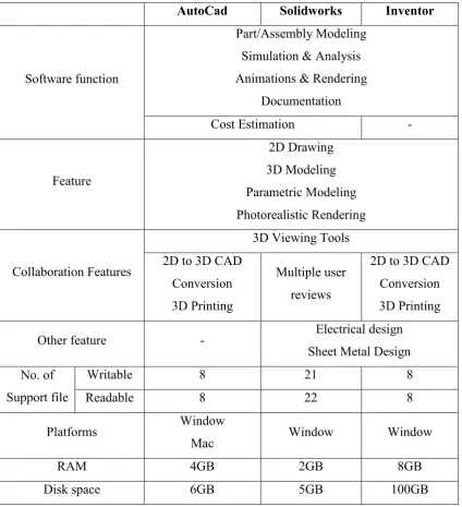
There are few research [10-16] had discuss to the feature between several 3D design software. This section will summarise the basic feature of AutoCAD, Solidworks and Inventor 3D design software. Table 1 is shown the target user of the 3D design software. Table 2 is the comparison the specification strength between these software.
Table 2.1: Invented user of 3D softwares.
AutoCad Solidworks Inventor
Architects Engineers Industrial
Designers
Students / Casual Users
Engineers Industrial
Designers
Students / Casual Users
Architects Engineers Industrial
Designers
Students / Casual Users
random access memory and disk space to perform well this software, there will be a problem if the platform is not achieve the minimum requirement. Therefore, Solidworks software is a step of behind Inventor. The Solidworks is consists the mostly feature of Inventor but just lack feature on 3D printing and the performance speed will a bit slow compare to inventor. For AutoCad software, it functionality and feature is roughly similar to two others and it is also suitable to design 3D object. But Solidworks software had been chosen in this project is because Solidworks software enables analysis and simulation as Inventor software, also obtain a good feature and performance speed rather than AutoCad.
Table 2.2: Basic data of three 3d design software.
AutoCad Solidworks Inventor
Software function
Part/Assembly Modeling Simulation & Analysis Animations & Rendering
Documentation
Cost Estimation -
Feature 2D Drawing 3D Modeling Parametric Modeling Photorealistic Rendering Collaboration Features
3D Viewing Tools 2D to 3D CAD
Conversion 3D Printing
Multiple user reviews
2D to 3D CAD Conversion 3D Printing
Other feature - Electrical design
Sheet Metal Design No. of
Support file
Writable 8 21 8
Readable 8 22 8
Platforms Window
Mac Window Window
RAM 4GB 2GB 8GB
2.2 Signal Graph Plotting Software
Matlab software is a strongest software in data processing field, this section is to discuss about the weather Processing software able to plotting a real time graph. Processing has promoted software literacy, particularly within the visual arts, and visual literacy within technology. Initially created to serve as a software sketchbook and to teach programming fundamentals within a visual context, Processing has also evolved into a development tool for professionals. The Processing software is free and open source, and runs on the Mac, Windows, and GNU/Linux platforms. Its open source status encourages the community participation and collaboration that is vital to Processing’s growth. Contributors share programs, contribute code, and build libraries, tools, and modes to extend the possibilities of the software. The Processing community has written more than a hundred libraries to facilitate computer vision, data visualization, music composition, networking, 3D file exporting and programming electronics. There are some example plotting graph sources to enable user to modify and develop own code to draw the graph line. This processing software is using programming code to generate the user interface window, so, concept and source code of Processing software is similar to Arduino IDE code. However, Matlab is the more powerful software compare to processing and there are a lot of specific method and feature to process the data signal inside of library Matlab and this software require a high random access memory and disk space to run the program.
In summary in this section, the purpose to choose a quick solution and software that is suitable to plotting a real time graph, therefore, Matlab software is suitable to plotting graph but not a necessary need to use it because the Processing software able to plotting graph with using a low memory in window platform.
2.3 The Prosthetic Hand
prosthetic hand in pass 500 hundred years ago. In 1500s, there is a right arm made by iron material (Ohry, 2014) and different appearance compare to previous version shown in Figure 2.1.
Figure 2.1: The Von Berlichingen, made of iron, 1500s
(Image sources from: http://commons.wikimedia.org/wiki/Category:Eiserne_Hand)
This design is mimic to real hand and this design idea is still been use until now. This prosthesis hand built up by iron material, causing the weight of this hand is heavy than old version which prosthesis is only attach with a hook (Figure 2.2) on the front end of the hand. Besides, at mid-19th century the prosthetic hand are made of leather, wood, and iron. The material of prosthesis hand is not only using iron and this innovation are multi attachment prosthetic hand. This design idea is also still been until nowadays. Control algorithms for upper limb myoelectric prostheses have been in development since the mid-1940s [2].
Based on Ahmed M. El Kady, Ahmed E. Mahfouz and Mona F. Taher (2010), the mechanical design is one of the main components of an upper limb prosthesis [3], therefore, this paper is aimed to build an Anthropomorphic Prosthetic Hand for Shape Memory Alloy Actuation presents and the objective of the mechanical design is to have an anthropomorphic hand (similar in size and structure to the human hand) and kinematic accurate movement to fulfil normal grip requirements. In this paper, there are implement two prototype. Both prototypes mechanical structure are consist of 3 phalanges; the joints between them, PIP, DIP and MCP, are interconnected with single DOF hinge joints, each joint is using torsion spring to force the finger extent and cause hand open. First prototypes is using Ertalon hollow tube material, a polymer which features high mechanical strength and good electric insulator properties. Each joint have 2 interlocking hinge with using steel pin to lock down all hole which linking interface of two different part. Plexiglas material is use for palm part and each actuation cable is fixed at end or fingertip of all fingers. Second prototype is four fingers are consist three segments with interlock and two segments inter locking for thumb. By using SMA wires and provide a small strain to generate an optimum joint rotation (flexion), therefore, this wire attach closely to the DIP joint (at the middle). After testing and evaluation, the second prototype is more suitable as prosthesis compare to first prototype because SMA actuator in second prototype is just need a small force to execute grasp motion and clasped an object. Therefore, when the length and segment of thumb also is a main criterial when design a prosthesis hand. Figure 2.3 and Figure 2.4 is showing the different contact area and the gap between two fingers when grasping a same object.
Figure 2.4: Model of second prototype grasping a cylinder with 2-segment of thumb [3]
In review on this paper, advantage of this mechanical design is light weight (printed by 3D printer) and no sound produce when it operate. Besides, this paper had clearly show that the longer length and three segment of thumb the higher forces needed to grasp an object to prevent slip, however, shorter length and two segment of thumb will require a small force and easy to grasp an object.
Figure 2.5: Image of multifunctional prosthesis hand [4]
For sensing input signal part, this paper are using myoelectric sensors and real time pattern recognition. In review on this paper, although this prosthesis design and concept of hand system were very powerful on functionality but there is some defective part which is the greater number of motor, the heavy the weight of hand and the second regret is this journal has target to use myoelectric sensor as input of control system but without discuss about the method being use for processing and analysing of signal part.
Figure 2.6: Mechanical hand design with one actuator [5].
In fact, if the pulling force generate from tie rod is greater than force from spring, the hand will close, if lower than, it will be open. The outstanding of this design is all fingers is move independently even using one actuator in the system. This incident is due to the great functional of pulley system which the tie pass through routine. The testing result shown that this design is able to grasp several surface object. In review on this paper, found out that this design is modular, light weight and low cost which printed by 3D printer using polyactide (PLA) material and it also able to grasp even more complex surface area of an object. However, the finger is move independently but there are a fix function which is grasping. There are limited gesture can be carry on this design.
one master node, nine slave nodes and one Microchip dsPIC33FJ128MC controller with frequency 8MHz. In overall control system design an linear actuator act as a feedback tool for sensing position of finger and also the master node is same as slave node, the only different is slave nodes have extra EEPROM memory which to store sequence of finger position. In servo control design, applying continuous-time model formula:
𝐺(𝑠) = 2.2 𝑠( 0.07𝑠 + 1 )
Figure 2.7: The control system create by MATLAB [6].
Figure 2.8: The mechanical structure of fingers [7].
Therefore, the overall of mechanical design consist of 20 joint and the movement of finger is driven by four links which connect to the three actuator (one for index finger, one for thumb and last for the left 3 fingers).
Figure 2.9: control system diagram [7].
types of function and built by using 3D printer. Light weight (apply less actuator) and low cost (under $1,000) is the outstanding for this design.
2.4 Conclusion
CHAPTER 3
METHODOLOGY
This chapter discusses about the methods used in conducting this project. In the beginning of this chapter, it explained the concept of the project by using flow chart. Then, the technique and software used or applied in this project will be illustrated as well. This chapter is divided into few sections including project flow, project methodology, workflow and procedures applied in this project. Figure 3.1 shows the basic concept on how the hand prosthesis operates.
Figure 3.1: Operation of myoelectric prosthetic hand [10].
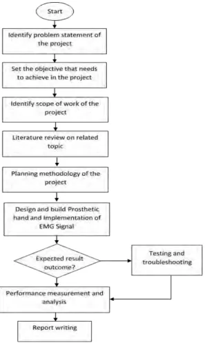
3.1 Project Flow
implementation of the system, methodology of the project is being done beforehand that acted as a guideline. The prosthetic hand is designed using “SolidWork” and developed by using 3D printing technology. The prosthetic hand is being controlled by using electromyography. The process of testing and troubleshooting is carried out to solve the problem when result obtained is not as expected. Lastly, measuring and analysing the system performance is done and then followed by report writing.
3.2 Project Methodology
This project is distributed in three parts, including mechanical fingers design, external power motor driver part and EMG signal analysis and processing as shown in figure below.
3.3 Work Flow
3.3.1 Mechanical Fingers Design
Firstly, the prosthesis hand design used in this project is a set of open source design. It consists nine joints which driven by three independent actuators. This design also is a 3D printable design. This design fulfils the objectives of the project which is modular, low cost and light weight. But due to the limitation of the design, all fingers needed to be modified by adding one extra joint without changing the length of the fingers or the original design of other parts.
Solidwork software is being use to redesign the fingertip part. The method of redesigning is by cutting the original fingertips to become three parts, whereby the first part is to vertically cut it to become one middle part and one new fingertip. Second part is to cut the middle part horizontally to make it separated into upper and lower part. Lastly, the designing process proceed to the joint connection part which call hinge point of finger including front, back, up or down of the finger joint.
Figure 3.4: the mechanical structure of finger design.
Figure 3.5: The dimension structure of finger design part 1.
Figure 3.6: The dimension structure of finger design part 2.
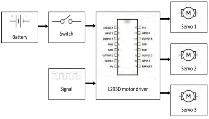
3.3.2 Motor Driver Circuit Design
This section illustrates about servo motor controlling. In this project three servo motor will be used in controlling the movements of the finger. Sufficient power is needed to ensure three servo motor can be driven at the same time with strong force/torque.
Figure 3.8: the block diagram of circuit design
3.3.3 EMG Signal Processing
The raw EMG signal is the input of the control system for this project. The first part is by establishing communication between computer (PC) and ARDUINO. PC needs to receive the raw signal to collect all the sampling data. The method of establishment of communication between PC and ARDUINO is done by using serial port communication. MATLAB software provides an electronic base platform called “Simulink” for programming ARDUINO. Simulink can use to create serial port by using component block inside the Simulink library.
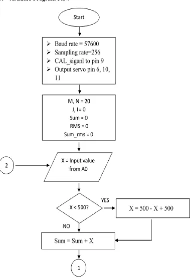
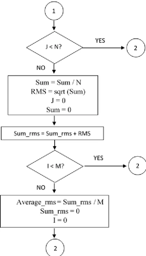
3.3.4 Arduino Program Flow
Figure 3.10: The flow chart of program code part 2.
In order to obtain the threshold value, a second check condition with count M is used to take the RMS value through looping until twenty times. The total value of RMS value will be divided by M to obtain the average value, then M is reset to 0 again. This looping conditions are continuous and it will repeat the previous step which started from reading EMG value as input until the average RMS value has been obtained.
[image:38.595.175.475.233.589.2]3.3.5 Control System
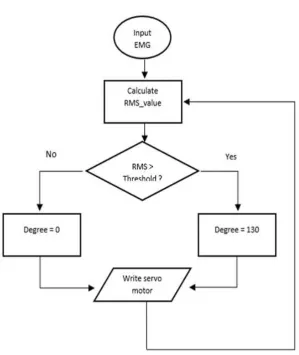
Figure 3.11: The basic flow chart diagram of control system.
Figure 3.12: Corresponding muscle position to control each fingers.
After obtaining the raw EMG signal, the data signal is being calculated using root mean square (RMS) formula to obtain an average RMS values for hand grabbing and opening gesture. The calculation of threshold value is being shown in section 3.3.3. This threshold value is used as a reference to trigger the different movement of the fingers. If the value RMS greater than threshold, the prosthetic hand will perform hand grabbing gesture while RMS value is lesser than threshold, the prosthetic hand will perform opening hand gesture. Another program is needed for the setting of the motor’s angle and to drive the motor corresponded to the angle set. Then, the program will loop back to read the input EMG signal.
3.4 Conclusion
CHAPTER 4
RESULT AND DISCUSSION
This chapter discusses about the result obtained from this project. The result is presented by using figures and table including explanations. The issues or problems faced throughout the project will be discussed in this chapter as well.
4.1 Result of Design Prosthetic Finger
This section discusses about finger design and development. The project is designed to be a 3 joints prosthetic finger that allows the actuation mechanism to increase the number of active DOF and provide a better functionality compare to 2 joints fingers. In addition, the 3 joints prosthetic fingers is designed to mimic hand movements such as opening and grabbing. This section covers only the mechanical design of the finger, such as the size, shape, joint and degrees of freedom.
A prosthetic hand design is very complex, it requires a lot of time to do research, calculation and testing. Therefore, modify an open source 3D prosthetic hand design of originally two joints finger design to three joints finger design can reduce the complexity of designing the prototype . The end product of the hand design and its control system is similar to the original design of two joints prosthetic finger.
4.1.1 Finger Design
Figure 4.1: The original finger of prosthetic hand.
.
Figure 4.2: The prototype design of finger design.
Figure 4.3: The prototype dimension of fingertips.
Figure 4.4: The prototype dimension of upper middle phalanx.
Figure 4.6 shows the finger design in plane facing to the right to provide a good view of three separate parts that have combined together. The fingers designed were assembled together with the whole hand design inside SolidWork for simulation of the hand shown in Figure 4.7 whereby the hand can be seen moving accordingly to the setting done. For example, the finger can be set to move according to specific angle of 10 degree once being set inside SolidWork.
Figure 4.6: The prototype of finger design.
Figure 4.7: The prototype of finger design and assembly the whole hand design.
4.1.2 Build the Prosthetic Hand by using 3D Printing Technology
[image:43.595.176.463.343.578.2]Figure 4.1.7(a) and (b) show the object design being converted into G-code using Cura software. Cura software is a software that ensures all the object arranged accordingly on the plate in 3D. In addition, this software can assist on directly importing multiple object files into a plane for printing. As compare to Axon software, the software is unable to support multiple objects inside a plane for printing. It only manage to print the design one by one which is very inconvenience. There are few settings that needed to be configured in Cura including the adjustment of the quality of end product and support part that to hold the printing object which can easily collapse during printing. Figure 4.8 and 4.9 show the G-code of after the configuration of the quality and all the support lines of end product which is being pre-observed using Cura software.
Figure 4.8: Using Cura software to display the G-code of plam and plam cover.
heater plate when it was cooled down to prevent the product from deforming as it was not solid yet. The product printed was then being cleaned and polished using sand paper.
Figure 4.10: Beginning state of 3D printing.
Figure 4.11: Complete state of 3D printing.
[image:45.595.175.463.384.589.2]renewable or green sources such as sugar cane, starch and corn. As a result, it can easily being renewable. It is used in most of the manufacturing processes that design 3D models and prototypes of plastic-based. In fused deposition modelling (FDM) technology, the molten polymer filament, which is extruded from the controller nozzle, is polylactic acid. PLA is a popular and commonly used raw plastic material in 3D printing, after acrylonitrile butadiene styrene (ABS), which comes in both hard and soft forms. Both are suitable for a variety of applications. Polylactic acid is also known as polylactide acid.
Figure 4.12: PLA material for 3D printing.
release toxic gas when being heated up. This is the reason ABS material has been rejected for material selection because it is not a user friendly material and it has the potential to harm human health. On the other hand, CPE material has been rejected is because of the cost of CPE material is higher than PLA and ABS material.
[image:47.595.233.406.165.400.2]Figure 4.13: PLA material for 3D printing.
Figure 4.13 is the end product of 3D printing which had been completely assembled. This end product marks the achievement of objective which is building a modular, light weight and low cost prosthetic hand. Besides, 3 servo motors are assembled inside this prosthetic hand. Thumb is activated by using one small size servo motor, index finger is controlled by one regular size of servo motor and the other fingers shared another one small size of servo motor for operation.
4.2 Result of Controlling Actuator
driver shield and controlling actuator by using Arduino UNO processing board was presented in this section.
[image:48.595.176.460.163.391.2]4.2.1 Motor Driver Circuit Design
Figure 4.14: The circuit board diagram of motor driver shield.
The rapid prototyping design was implemented for two different size of servo motor. In the total 3 servo motors had been used the trigger the motion of fingers. The processing board of this project is Arduino UNO but the current delivery by Arduino is only 50mA not enough to trigger up 3 servo motors operate at the same time. Therefore external power is needed to increase the voltage and current when driving three servo motors. L293d motor driver had been chose and built a motor driver shield with using external double battery as external power. By using Eagle software a board diagram had been designed as shown in Figure 4.14. Hence, the board diagram had been printed out and built with using ultra violet PCB board.
Figure 4.15: Completed of hardware connection.
In Figure 4.15,the left hand side was the 3D printed prosthetic hand, right hand side was the four piece of 1.5V double a battery and the centre part is combination of shield, bottom is the Arduino UNO, middle is the EKG/EMG shield and top is the motor driver shield.
4.2.2 Arduino Code
After motor driver circuit section is the programing to Arduino board section. First, the open sources have servo code library therefore need to include before start to control as code below.
Second, is need to declare the variable being use to control the movement of servo motor. In this project, there are consists of three servo motor, therefore, three variable had been declare as shown in Figure 4.16 upper part. Inorder to check the feedback from the servo motor means to detect the current position of the servo motor, three integer variable had been declare shown in Figure 4.16 lower part for record and further checking purpose. The naming of the variable is ensure programmer easy to recoignize the servo motor is belong with which finger and easy to debug when error occur.
Battery Motor Driver shield
+
EKG/EMG shield +
Arduino UNO 3D printed
Figure 4.16: Code of declaring servo motor variables.
Figure. 4.17: Assign pins of servo motor variables.
The last on this section is assign the pin of servo motor variable (Figure 4.17) at the same time servo motor in prosthetic hand is connected according to following pin. Then the reason of choosing pin 6, pin 10 and pin 11 is because of PWM I/O, because the servo motor is trigger by pulse width modulation signal and pin 9 is being use by EKG/EMG shield.
4.3 Result of Electromyography (EMG) Signal Processing Technique
4.3.1 Capture EMG Signal
Figure 4.18: Olimex EKG/EMG shield.
Figure. 4.19: Code of EMG Shield configuration.
4.3.2 Signal Processing
Figure 4.20: Code of rectifier the EMG raw signal.
Figure 4.21: Code of RMS value.
After collect a numbers (n) of data, the total of sum need to divide by (n) and call the square root equation in math.h library to calculate the final root mean square value as shown in Figure 4.21, these two line of code need to write at outside of data collection loop.
4.3.3 Plotting Graph
Figure 4.22: Processing Code of read serial COM port.
The Figure above is the code for draw a real time graph. In the draw function stroke(R, G, B) is to represent the colour of graph line, strokeWeight(n) is to represent the weight of the line. In order to continue drawing the line, the current x axis and y axis position will set to lastxpos and lastheight purposely use for next calling this draw function.
Figure 4.23: Processing Code of plotting EMG signal graph.
[image:54.595.181.458.353.544.2]Figure.4.24: Graph of EMG raw signal.
Figure 4.25: Graph of EMG raw signal after rectifier.
Figure 4.26: Graph of EMG signal after root mean square.
[image:55.595.206.433.433.575.2]4.4 Control Movement of Finger by EMG Signal.
4.4.1 Result on Testing Servo Motor Angle
[image:56.595.149.506.326.434.2]In this section, the movement of the finger was controlled by EMG signal. Before this all the servo motor was tested the corresponding movement angle for each servo and it is related to the mechanism design of prosthetic hand. Table below are the testing result of the angle of prosthetic fingers. The reason of using the servo motor library, the required input is angle, means key in an input angle it will directly generate a proper pulse width modulation signal to the serve motor and the servo motor will rotate to the corresponding position.
Table 4.1: Result of corresponding angle for all fingers.
Fingers Angle of open ( 𝑑𝑒𝑔𝑟𝑒𝑒𝒐)
Angle of close ( 𝑑𝑒𝑔𝑟𝑒𝑒𝒐)
Thumb 124 67
Index 150 0
Other fingers 140 40
4.4.2 Result Code of Open and Close All Fingers
[image:56.595.139.497.500.746.2]4.5 Discussion
4.5.1 Modular Prosthetic Hand Design
4.5.2 Low Cost Prosthetic Hand Design
Table 4.2: The estimation cost for this project.
ITEMS COST
ARDUINO Around RM 50 (None warranty) Around RM 140 (with 6 months warranty)
EKG/EMG SHEILD Around RM 100
ECG-GEL-ELECTRODE Around RM 5
EKG-EMG cable Around RM50
Motor Driver circuit Around RM 30
Servo motor Around RM 200
Prosthetic hand material Around RM 50
Table above illustrated the estimation cost of all component been used in this project which in years 2016. The total cost prosthetic hand in this project for sure is below one thousand and lower cost compared to the price smart phone with high specification in the current market. This condition are fulfil the first objective to produce a low cost prosthetic hand.
4.5.3 Light Weight Prosthetic Hand Design
4.5.4 Under-actuated Myo-electric Prosthetic Hand
Figure 4.28: The EMG connector attached on muscle skin.
4.6 Conclusion
CHAPTER 5
CONCLUSION AND FUTURE RECOMMENDATION
5.1 Conclusion
As conclusion, a modular, low-cost and light-weight hand prosthesis has been successfully built. This design is affordable to all level of consumer and also applicable to lower limbs amputees as a prosthetic hand. Besides, this prosthesis hand is able to control by using the implementation of EMG signal from forearm muscle. This project is beneficial to the amputee who lost their hand and this can help limbs amputees to recover a part of self-confident and making them believe that there is still hope to regain back part of the lifestyle of a normal healthy person. This prosthetic hand design in this project can be applied to the a person as long as he/she still retain his/her forearm muscle.
5.2 Future Recommendation
REFERENCES
[1] Ohry, A. (2014). On limbless heroes. Progress in Health Sciences, 254-264. [2] AD. Roche; H. Rehbaum; D. Farina; OC. Aszmann, Current Surgery Reports,
2014 – Springer
[3] El Kady, A.M.; Mahfouz, A.E.; Taher, M.F., "Mechanical design of an anthropomorphic prosthetic hand for shape memory alloy actuation," in Biomedical Engineering Conference (CIBEC), 2010 5th Cairo International , vol., no., pp.86-89, 16-18 Dec. 2010
[4] Weir, R.; Clark, S.; Mitchell, M.; Puchhammer, G.; Kelley, K.; Haslinger, M.; Kumar, N.; Hofbauer, R.; Kuschnigg, P.; Cornelius, V.; Eder, M.; Grausenburger, R., "New Multifunctional Prosthetic Arm and hand Systems," in Engineering in Medicine and Biology Society, 2007. EMBS 2007. 29th Annual International Conference of the IEEE , vol., no., pp.4359-4360, 22-26 Aug. 2007 [5] Niola, V.; Rossi, C.; Savino, S.; Troncone, S., "An underactuated mechanical hand: A first prototype," in Robotics in Alpe-Adria-Danube Region (RAAD), 2014 23rd International Conference on , vol., no., pp.1-6, 3-5 Sept. 2014
[6] Chwan-Hsen Chen, "Virtual Model for a Multi-finger Robot Hand Design," in Computational Intelligence, Communication Systems and Networks (CICSyN), 2012 Fourth International Conference on , vol., no., pp.176-180, 24-26 July 2012 [7] Gamez, B.; Cabrera, M.; Serpa, L.; Cabrera, J., "Mechatronic Hand Prosthesis for Child," in Computer Aided System Engineering (APCASE), 2015 Asia-Pacific Conference on , vol., no., pp.354-359, 14-16 July 2015
[8] Polhemus, A.; Doherty, B.; Mackiw, K.; Patel, R.; Paliwal, M., "uGrip II: A Novel Functional Hybrid Prosthetic Hand Design," in Bioengineering Conference (NEBEC), 2013 39th Annual Northeast , vol., no., pp.303-304, 5-7 April 2013.
[10] G. Kondo, "人 工 知 能 研 究 セ ン タ ー 交 流 会 ポス タ ー(2016.3.25)",
Slideshare.net, 2016. [Online].
[11] L. He, G. Wu, D. Dai, L. Chen and G. Chen, "Data conversion between CAD and GIS in land planning," Geoinformatics, 2011 19th International Conference on, Shanghai, 2011, pp. 1-4.
[12] R. Wang, "Development of Parametric Drawing Program Based on AutoCAD VBA," Computational Aspects of Social Networks (CASoN), 2010 International Conference on, Taiyuan, 2010, pp. 757-760.
[13] Guangmin Sun, Lei Xu, Deming Chen, Gang Li and Jing Wang, "A system scheme of 3D object reconstruction from single 2D graphics based on neural networks," 2008 6th IEEE International Conference on Industrial Informatics, Daejeon, 2008, pp. 1081-1085.
[14] F. Fittkau, E. Koppenhagen and W. Hasselbring, "Research perspective on supporting software engineering via physical 3D models," Software Visualization (VISSOFT), 2015 IEEE 3rd Working Conference on, Bremen, 2015, pp. 125-129.
[15] G. Mandalaki and S. Manesis, "3D Simulation Analysis of Patras New Port Operations in SIMIO Platform Environment," Computer Modelling and Simulation (UKSim), 2013 UKSim 15th International Conference on, Cambridge, 2013, pp. 554-558.
[16] R. Sam, K. Arrifin and N. Buniyamin, "Simulation of pick and place robotics system using Solidworks Softmotion," System Engineering and Technology (ICSET), 2012 International Conference on, Bandung, 2012, pp. 1-6.

![Figure 2.5: Image of multifunctional prosthesis hand [4]](https://thumb-us.123doks.com/thumbv2/123dok_us/136437.13581/23.595.174.465.69.271/figure-image-multifunctional-prosthesis-hand.webp)
![Figure 2.7: The control system create by MATLAB [6].](https://thumb-us.123doks.com/thumbv2/123dok_us/136437.13581/26.595.118.519.70.391/figure-control-create-matlab.webp)